Table of Contents
Advertisement
Advertisement
Table of Contents

Summary of Contents for devox AERO-TRI BAR
-
Page 1: Instruction Manual
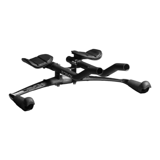
AERO-TRI BAR FELT CARBON FIBER AERO B AR INSTRUCTION MANUAL... -
Page 2: Table Of Contents
TA BL E OF CO NTENTS Introduction ............Parts list . -
Page 3: Introduction
AERO-TRI BAR IN TR ODUCTION Thank you for purchasing the Felt aerobar system. Like all Felt products, this aerobar is engineered to offer maximum adjustability and dependability while being easy to use and service. Because this is a precision engineered product we ask you to take great care in its installation and use. -
Page 4: Parts List
PA RTS LIS T QTY. SIZE - PART NAME PART M6 x 55mm - Bolt M6 x 50mm - Bolt M6 x 45mm - Bolt M6 x 40mm - Bolt M6 x 35mm - Bolt M6 x 30mm - Bolt M6 x 25mm - Bolt M6 x 20mm - Bolt M6 x 15mm - Bolt... - Page 5 AERO-TRI BAR QTY. SIZE - PART NAME PART Basebar Extension Extension Plug Extension Bracket Armrest Bracket Narrow Fixed Bridge Wide Fixed Bridge QTY. 40mm 30mm 20mm 10mm SIZE PART Threaded Spacer Threaded Spacer Threaded Spacer Non-Threaded Non-Threaded Spacer Spacer...
- Page 6 OVERVIEW The below reference highlights the five main areas of adjustment that can be manipulated to achieve the desired configuration. 1. Armpad position & angle 2. Armpad fore & aft 3. Arm pad width 4. Extension width & angle 5. Extension fore & aft 6.
-
Page 7: Overview
AERO-TRI BAR OVERVIEW For riders who prefer a narrower position, further adjustment can be achieved by flipping the extension brackets 180 degrees to position the extensions closer together. See two images below for demonstration. Shown below is an example of a low-stack configuration with a wide arm pad and extension position. -
Page 8: Configuration Reference Chart
CO NFIGURATION REFERENCE C HART BEFORE BEGINNING ASSEMBLY OF AEROBAR, READ THE CHART AND NOTES ON STACK HEIGHT BELOW. If you know the dimensions that you require while riding a TT/TRI bicycle, the chart below will help you quickly identify the hardware required to achieve your desired stack height. -
Page 9: Step 1: Stack Height & Riser Assembly
AERO-TRI BAR Step 1: Stack Height & Riser Assembly Option A 5mm +10mm - One extension - Two top bolts (55mm) - One extension bracket - One bracket spacer* - Stack height spacers (5mm + 10mm) - Fit washers (6)** - One threaded lower nut Option A. -
Page 10: Step 2: Armrest Assembly
*BRACKET SPACER Insert the bracket spacer into the slot located on the extension bracket, making sure to align the holes and leave the long, curved edge flush with the edge of the extenion bracket slot as shown in the illustration to the right. **FIT WASHERS Begin with pressing the fit washers into the recessed holes. - Page 11 AERO-TRI BAR Possible armrest configurations Notice that the diameters of the six holes in the arm rest are each larger than the diameter of the bolt shaft. This allows for fine-tuning to achieve desired arm pad angle. See below for illustrations.
-
Page 12: Step 3: Final Assembly
Step 3: Cable Routing Routing the brake and shifter cables can be made easier by following these suggested steps: *Note- when using electronic shifters, be sure to route the electronic wire before inserting the brake housing. 1. Insert the steel inner cable, starting at the rear of the bar. -
Page 13: Notes & Dimension Log
AERO-TRI BAR Notes & Dimension Log Your Dimensions: Name ______________________ Date __________ Stack height __________mm Arm pad width __________mm Extension width __________mm Stem Length/rise __________mm/__________degrees Frame______________________ Notes: Your dimensions: Name ______________________ Date __________ Stack height __________mm Arm pad width __________mm...
Need help?
Do you have a question about the AERO-TRI BAR and is the answer not in the manual?
Questions and answers
hello! Since the diameter for a stern is very small, which one do i have to get? Thanks in Advance!
The appropriate size of the Devox AERO-TRI BAR for a small stern diameter is not specified in the provided context.
This answer is automatically generated