Table of Contents
Advertisement
SPEED-Commander
Universal frequency inverter
Standard user guide
Version 5.x.x
Universal AC-Motor-Controller
With integrated:
• Speed control
• PI-regulation
• Positioning
• Synchronous Control
• Torque limiting
STRÖTER Antriebstechnik GmbH
40549 Düsseldorf . Krefelder Straße 117 . Telefon: 0211/95600-0
40522 Düsseldorf . Postfach 19 03 27 . Fax: 0211/504415
http://www.stroeter.com/
-
info@stroeter.com
Advertisement
Table of Contents

Summary of Contents for STROETER SC 750/5
- Page 1 Universal AC-Motor-Controller With integrated: • Speed control • PI-regulation • Positioning • Synchronous Control • Torque limiting STRÖTER Antriebstechnik GmbH 40549 Düsseldorf . Krefelder Straße 117 . Telefon: 0211/95600-0 40522 Düsseldorf . Postfach 19 03 27 . Fax: 0211/504415 http://www.stroeter.com/ info@stroeter.com...
-
Page 2: Table Of Contents
Standard user guide SPEED-COMMANDER Index: The Speed Commander Introduction ......................3 Frequency inverter are used Generally....................3 to control the speed of a 3 phased ac motor. Properties / advantages ................3 This generation of the Speed CE-Approval....................4 Commander is developed to be used in all sorts of Technical specifications................4 industrial applications. -
Page 3: Introduction
Standard user guide 1 Introduction 1.1 Generally The Speed Commander V5 is a static frequency inverter with DC-link voltage for continuously variable speed control of AC motors. • Vector modulation and 16bit microprocessor • Display for - Motor frequency, current, DC link voltage, parameters, error codes, positions and more. •... -
Page 4: Ce-Approval
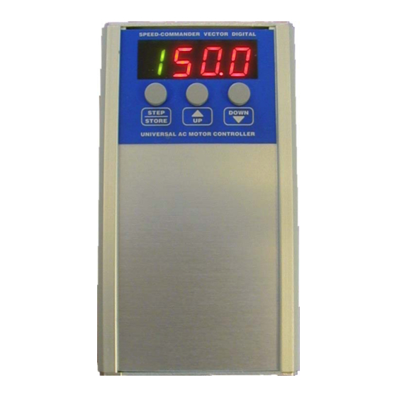
Standards for emission EN 50082-2 Standards for immunity (Industrial area) 1.4 Technical specifications Type: SC 750/5 SC 1500/5 SC3-1100/5 SC3-2200/5 230 V ± 10% / 50 - 60 Hz 3 x 400 V ± 10% / 50 - 60 Hz Mains supply: Max. - Page 5 Standard user guide Mechanical measures: SPEED-COMMANDER VECTOR DIGITAL STEP DOWN STORE UNIVERSAL AC MOTOR CONTROLLER Type: SC-750/5 SC-1500/5 and SC3-2200/8 SC3-1100/5 SC3-4000/5 SC3-5500/5 and SC3-7500/5 SC3-11000/5 SC3-22000/5 V51-00-V19 eng Rights to changes reserved...
-
Page 6: Power And Torque Curves
Standard user guide 1.5 Power and torque curves When setting up a drive the torque sequence must be considered in the wanted regulation area. This can roughly be divided into 3 groups: • Constantly torque in all regulation area e.g. conveyer •... -
Page 7: Installation
Standard user guide 2 Installation 2.1 Generally The SPEED-COMMANDER frequency inverter makes it possible to regulate the speed of a 3-phased AC motor in power ranges until 22Kw This manual must follow the inverter to secure correct installation. Please check the following points: •... -
Page 8: Decision Of Motor Direction
Standard user guide Note! • High ambient temperature reduces the electronically lifetime considerably. • If fan is mounted please check it frequently. • The Speed Commanderen must not be exposed to vibrations, humidity, water, dust and aggressive gasses. • Max altitude: 1000 meter above sea. Reductions factor: Ambient temp.: Output current:... -
Page 9: Parameter Setting
Standard user guide 2.5 Parameter setting Factory setting: When delivered the inverter is set to the most common operation conditions. This should always be checked and adjusted to task required. For information about the parameter see page 9 and the following pages. Setting procedure: SPEED-COMMANDER VECTOR DIGITAL 1) Push STEP / STORE and the green... -
Page 10: Parameter Table - Standard Frequency Inverter (Program 0)
Standard user guide 2.6 Parameter table – Standard frequency inverter (program 0) Function: Range: Defaults: Description: Max. Frequency 0,0 - 400 Hz 50,0 Hz Frequency at max analogue input = (10V or 20mA) Min. Frequency 0,0 - 400 Hz 2,5 Hz Frequency at min analogue input = (0V or 0 / 4mA) Acceleration 0,01 - 999 Hz/s 5,0 Hz/s... -
Page 11: Notes To Parameters
Standard user guide 2.7 Notes to parameters Note: Most of the parameters in the The non flashing parameters will normally have the same Speed Commander can be set up at run functions in the special programs. The flashing parameters time. This must be done with care are different from program to program. - Page 12 This parameter is used for compensating for the motor slip. The output frequency will start at the value set in this parameter Recommended values for Par. 6/7/A Type: Par. 6 Par. 7 Par. A SC 750/5 SC 1500/5 [Hz] SC3-1100/5 Deceleration after SC3-2200/5 SC3-4000/5...
- Page 13 Standard user guide Par. A: Stop frequency This parameter works as parameter 9 but this is active when decelerating. Par. B: Current limit This can adjust the output current limit from 50% to 150%. If the current limit is exceeded does the display flash and the output frequency is reduced, Par.
- Page 14 Standard user guide Par. F: Display readout 1 Output frequency [Hz] Scaled by Par. G 10 Motor current [A] Shows the actual motor current Value: Mains supply x √2 20 DC Link voltage [VDC] 30 Position readout Shows only the first 3 digit: 12.4 Sample value: 12.406 Scroll: 12.406 = 12.
- Page 15 Standard user guide Par. H: Relay functions Terminal 14,15,16 (Relay 220 V / max. 1 A) Activated at fatal TRIP (Error codes OH , OU , OC) Note: A green dot at left are on when the relay is on. Inverted function of 0.
- Page 16 Standard user guide Par. J: Function for terminal 9 DC-STOP-input or NPN output 0-99 Same function as Par. H Relay function NPN output. DC-STOP-input (DC brake) Parameters to set: 7 / 8 / A Note: When used as a NPN output do NOT connect to +10V this will damage the inverter.
-
Page 17: Information About Positions Tolerance And Hysteresis (Par. U And Y)
Standard user guide Information about positions tolerance and hysteresis (PAR. U and Y) (Not available in program no. 0) The purpose with parameter U is to tell the inverter how accurate the positioning should be. If the ramps (acceleration /deceleration) were set too high would it result in problems with finding the right position precisely. -
Page 18: Error Codes
Standard user guide 2.9 Error codes Display Problem: Solution: Under voltage Check mains supply DC Link overloaded –Inverter defect Check all 3 phases on the SC3-xxxxx Over voltage Check mains supply Try to decrease deceleration time (Par. 4) Use a inverter with Brake chopper Inverter Overheat Check mounting (free space around), fan and load. -
Page 19: Mains Supply
Standard user guide 2.10 Mains supply Net: 230 V ±10% / 50/60 Hz 3 x 400 V ±10% / 50/60 Hz Type: SC 750/5 SC3-1100/5 SC3-5500/5 SC3-11000/5 SC 1500/5 SC3-2200/5 SC3-7500/5 SC3-22000/5 SC3-4000/5 Motor 3x230V Motor 3x400V NOTE: When powering up the Speed Commander the display shortly shows the software version, model no and program no. -
Page 20: Control Inputs
Standard user guide Recommended length on motor cables. Use choke Mains supply Motor wire length coils if longer cable is needed. 1 x 230 V / 50/60 Hz Max. 30 m 3 x 400 V / 50/60 Hz Max. 15 m Warning! There can be a high voltage at the DC link capacitors in up to 5 min after mains disconnection. - Page 21 Standard user guide Inputs 5-9 are PLC compatible and can be controlled with 10-24 VDC (PNP). Inputs 5, 6 and 7 have a minimum pulse length at 50 mSec duration. Input 7 is supplied with a PTC – resistor measure input to be used to motor protection. At a resistor value between 3KΩ...
-
Page 22: Emissions And Immunity
Standard user guide 2.12 Emissions and immunity SPEED-COMMANDER inverters are referring to EMC-directives 89/336/EWG tested after test standards EN 50081-1 (Emission) and EN 50082-2 (immunity) And keep these when the installation guide is followed. EMC correct installation: The Speed Commander, the noise filter on the mains and the shield on the motor and control cable, must be installed in a conduction unpainted assembly board. -
Page 23: Connection Samples For Program 0
Standard user guide 2.13 Connection samples for program 0 FWD/REVand stop PLC with PNP-output 10- 24 VDC Motor potentiometer / Ramp generator With 1 stage switch 9 10 11 12 Function 10 K Forwards Reverse Stop 2 rotation directions and 2 speeds Speed AUTO or MANUAL 3 speed with 2 relays Auto... -
Page 24: Connection Of Brake Motor And Resistor
Standard user guide 2.14 Connection of brake motor and resistor Rectifier ϑ ϑ 3xAC Important: Brake resistor is heated while system is running. Ensures free space to other components and mount touch protection -24- V51-00-V19 eng Rights to changes reserved... -
Page 25: Actual Settings
Standard user guide 3 Actual settings. Speed Commander type SC: Serial no.: Imax: Parameter No: Defaults: User settings: 1 Max. frequency (Hz) 50,0 2 Min. frequency (Hz) 3 Acceleration (Hz/sec.) 4 Deceleration (Hz/sec.) 5 V/F – curve (Hz) 50,0 6 boost(%) 7 DC current (%) 8 DC time (sec.) 9 Start frequency (Hz)
Need help?
Do you have a question about the SC 750/5 and is the answer not in the manual?
Questions and answers