Advertisement
Quick Links
Download this manual
See also:
Instruction Manual
Service Manual
Supplement
The construction of the model DC-DA380/AU is similar to the model DC-DA370/AU. Please also refer to the
original service manual DC-DA370/AU(SM5810214) for the items which do not appear in this supplement.
Contents
Exploded view (Cabinet & Chassis) ................................. 1
Parts list ........................................................................... 2
IC Block diagram & description ........................................ 5
Schematic diagram
(CD) ............................................................................... 6
(AMPLIFIER ) ................................................................ 10
Wiring diagram
(CD & FRONT) .............................................................. 8
(TUNER & AMPLIFIER ) ............................................... 12
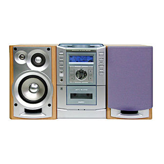
This service manual consists of "DC-DA380U/AU" (Main unit : 129 633 03) and
"SX-DA380L/UK" (Speaker system : 165 056 00) & "SX-DA380R/UK" (Speaker system : 165 057 00).
May / '02 BB
Printed in Japan
Micro Component System
SANYO Electric Co., Ltd.
Osaka, Japan
FILE NO.
DC-DA380
(AU)
PRODUCT CODE No.
129 634 03
SS
REFERENCE No.
5810301
Advertisement

Related Manuals for Sanyo DC-DA380


Summary of Contents for Sanyo DC-DA380
- Page 1 DC-DA380 Service Manual (AU) Supplement The construction of the model DC-DA380/AU is similar to the model DC-DA370/AU. Please also refer to the original service manual DC-DA370/AU(SM5810214) for the items which do not appear in this supplement. Contents PRODUCT CODE No.
- Page 2 EXPLODED VIEW (CABINET & CHASSIS) N.S.P : Not supplied as service parts. - 1 -...
-
Page 3: Parts List
PARTS LIST PRODUCT SAFETY NOTICE EACH PRECAUTION IN THIS MANUAL SHOULD BE FOLLOWED DURING SERVICING. COMPONENTS IDENTIFIED WITH THE IEC SYMBOL IN THE PARTS LIST AND THE SCHEMATIC DIAGRAM DESIGNATED COMPONENTS IN WHICH SAFETY CAN ! ! ! BE OF SPECIAL SIGNIFICANCE. WHEN REPLACING A COMPONENT IDENTIFIED BY , USE ONLY THE REPLACEMENT ! ! ! PARTS DESIGNATED, OR PARTS WITH THE SAME RATINGS OF RESISTANCE, WATTAGE OR VOLTAGE THAT ARE... - Page 4 PARTS LIST CD P.W.BOARD ASSY REF.NO. PART NO. DESCRIPTION D2153 407 105 1602 VARACTOR DI SVC342M-V REF.NO. PART NO. DESCRIPTION 407 105 1305 VARACTOR DI SVC342L-V 614 324 0921 ASSY,PWB CD(Only Initial) D2301 407 063 9108 ZENER DIODE MTZJ6.8B CN111 645 026 2463 SOCKET,FFC 15P D2451...
- Page 5 PARTS LIST POWER TRANSFORMER, REF.NO. PART NO. DESCRIPTION Q4600 405 155 0002 TR MPSA56 SECONDARY P.W.BOARD ASSY Q4601 405 000 3806 TR DTC114YS 405 143 0007 TR KRC107M The construction of "POWER TRANSFORMER,SECONDARY Q4602 405 019 3804 TR 2SC536-G-NP P.W. BOARD ASSY"(Ref.No75) is similar to that of DC-DA370/AU. 405 141 3307 TR KTC3198-GR 405 141 3208...
- Page 6 IC BLOCK DIAGRAM & DESCRIPTION IC101 LA9241ML (Servo Signal Processor) IC442 TDA7265 (Stereo Amplifier) Vcc1 BH1 PH1 LF2 VR REF1 Vcc2 DRF CE DAT CL CLK 54 53 RF DET MUTE/ U-COM ST-BY INTER FACE FIN2 IN (L) FIN1 OUT (L) DGND IN- (L) RFS-...
Need help?
Do you have a question about the DC-DA380 and is the answer not in the manual?
Questions and answers