Table of Contents
Advertisement
Quick Links
PILOT'S OPERATING HANDBOOK
and
FLIGHT MANUAL
RIDER
MD 3
BE CAREFULL !
Followed text of flight manual is only informative - prepared as the
background for whole world, adapted according to notices from Czech
LAA certification process and dealers wishes ...
It is not possible to use that without approving of domestic dealers or
certification offices in specific country verification.
( there is needed to be adapted mainly according to regional limits and
UL requirements directions )
Advertisement
Table of Contents

Summary of Contents for Flyitalia MD-3 Rider
-
Page 1: Flight Manual
PILOT'S OPERATING HANDBOOK FLIGHT MANUAL RIDER MD 3 BE CAREFULL ! Followed text of flight manual is only informative - prepared as the background for whole world, adapted according to notices from Czech LAA certification process and dealers wishes … It is not possible to use that without approving of domestic dealers or certification offices in specific country verification. -
Page 2: Date Of Issue
RIDER Flight manual MD-3 Rider Aircraft Type: / version Serial number: Registration: Date of issue: LAA Approval number and date: ULL - 02 / 2006 31.5. 2006 LTF Approval number and date: Manufacturer – stamp and signature The airplane must be operated by the information and limitations which are presented in this handbook. - Page 3 RIDER Flight manual LIST OF THE REVISIONS AND THE REPAIRS 11.4. 2006 Number of Date of issue It concerns to Signature Ordinal No. document - pages No. bulletin Page 3...
- Page 4 RIDER Flight manual 1. GENERAL 1.1. Introduction This handbook is provided with your aircraft to allow you to attain as much knowledge about the aircraft and its operation as possible. Read this manual before your first flight and make sure you understand all the information contained here.
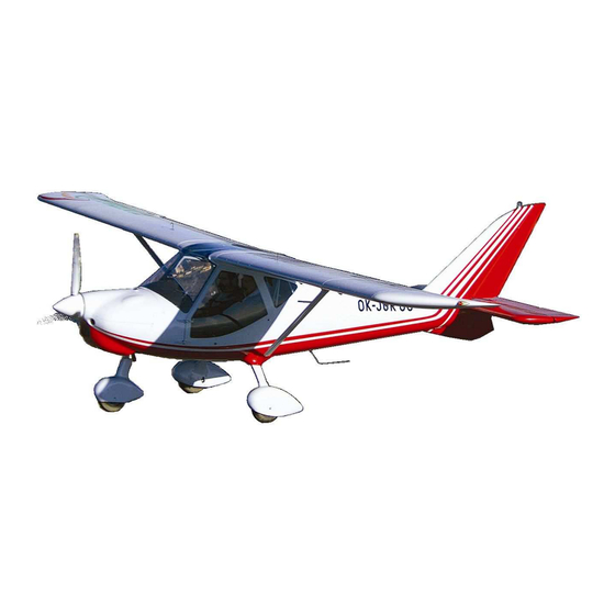
- Page 5 Flight manual 1.4. Aircraft basic description MD-3 Rider is an all metal design, light high-wing ultralight airplane with glued and riveted aluminum alloy airframe, welded cockpit cage and aerodynamic shaped composite fuselage canopy and fairings. The aircraft is equipped with 100HP Rotax 912 ULS engine (80HP...
- Page 6 RIDER Flight manual 1.5. Three-view drawing Page 1-3...
-
Page 7: Airspeed Limitation
RIDER Flight manual 2. LIMITATION 2.1. AIRSPEED LIMITATION Speed km/h Never exceed speed Maximal speed in hard turbulence Maneuvering speed Maximum flap extended speed WARNING: Above Maneuvering speed use smaller deflection of control surfaces only - the aircraft may be overloaded ! 2.2. - Page 8 RIDER Flight manual 2.3. Engine The MD-3 Rider is powered by ROTAX 912ULS engine, MD-3 UL model is powered by Rotax 912 UL. MD-3 UL MD-3 Aircraft Rotax 912 UL ROTAX 912 ULS Engine model Max. power- take-off (kW) 59,6...
- Page 9 RIDER Flight manual 2.4. Engine instrument marking The aircraft is equipped with an integrated engine display FLYDAT Display panel Description Unit Resolution RPM [1/min] Operation hours [hours] Exhaust gas temperature [ºC] Exhaust gas temperature [ºC] Cylinder head temperature [ºC] ← (→) indicates symbolizes left (right) cylinders, Oil temperature [ºC] Oil pressure [bar] Indicator Unit Warning limits...
- Page 10 RIDER Flight manual 2.5. Weight limitation 912 UL 912UL Empty weight (standard version, kg) Max. take-off weight (NO Ballistic Recovery System installed, kg) Max. take-off weight (Ballistic Recovery 472,5 472,5 System installed, kg) Max. crew weight - (kg) calculated for Min.
- Page 11 RIDER Flight manual 2.8. Maneuvering load factors G Flap Maximum positive center of gravity load factor up (0° ) Maximum negative center of gravity load factor Flaps Maximum positive center of gravity load factor down Maximum negative center of gravity load factor 2.9.
- Page 12 RIDER Flight manual 2.12. Other limitation WARNING: No smoking knots Max. crosswind component (5 m/s) knots Max. wind in runway direction (12 m/s) 50 ° C Maximum outside temperature - 25 ° C Minimum outside temperature Heavy rain or extensive moisture can cause mild decrease airplane performance.
-
Page 13: Airspeed Ias
RIDER Flight manual 2.13. PLACARDS Registration label Matriculation: GRYF Aircraft Producer: spol. s r.o. MD3 Rider Type/Name : Production number/year: Empty weight: Max. take-off weight: Basic international placards : This ultra-light aircraft been approved only for VFR day flights under no icing conditions. AEROBATICS maneuvers intentional spins are PROHIBITED ! -
Page 14: Engine Speed
RIDER Flight manual Examples of next specific placards : ENGINE SPEED 5 800 Max. Take-off (max 5min) 5 500 Max. continuous 1 400 Idling litre unleaded fuel MON 85 RON 95 min. Baggage max. tyre 180 +20 kPa Next used placards are classical for all aircraft – open/close, instrument description etc. - Page 15 RIDER Flight manual As example of specific regional placards, followed there are shown translated LAA CZ placards : OPERATION INFORMATION AND LIMITS Matriculation : Empty weight : Max. take-off weight : Max. payload : Max. baggage weight: Min. pilot weight: Max.
-
Page 16: Emergency Procedures
RIDER Flight manual 3. EMERGENCY PROCEDURES This section provides checklist and amplified procedures for coping with emergencies that may occur. Emergencies caused by airplane or engine malfunction are extremely rare if proper pre-flight inspections and maintenance are practiced. However, should an emergency arise, the basic guidelines described in this section should be considered and applied as necessary to correct the problem. - Page 17 RIDER Flight manual 3.1.3. In-flight engine failure - airspeed km/hod - trim trim - landing site selection select check situation ( actual flight level etc.) and continue according to procedure 3.2. (in-flight engine starting) or procedure 3.1.2 - if the engine cannot be started up 3.1.4.
- Page 18 RIDER Flight manual 3.3. FIRES 3.3.1. Engine fire on the ground - fuel tank valves shut - throttle full - ignition - master switch - abandon the aircraft and extinguish fire (if possible) - fire damage inspect WARNING: DO NOT CONDUCT ANOTHER FLIGHT BEFORE THE FIRE CAUSE HAS BEEN DETERMINED AND REPAIRED 3.3.2.
- Page 19 RIDER Flight manual 3.3.4. Cockpit or electrical fire - cockpit door open to remove smoke from the cockpit - radio, gps or other switches Land as soon as possible. Extinguish fire as soon as possible. 3.4. Gliding optimum gliding speed km/hod 1:10 Gliding ratio (at 110 km/hod)
- Page 20 RIDER Flight manual 3.8. Vibrations or other engine problem Vibrations: - set engine speed to such power setting where the vibrations are minimum - land as soon as possible, consider off-airfield landing, especially when vibrations are increasing Oil pressure drop – an engine failure is probable in this case: Reduce the engine power and land as soon as possible (before an failure occurs ), consider off-airfield landing.
- Page 21 RIDER Flight manual 3.12.2. Spin recovery WARNING: Spin characteristics of this airplane have not been tested. A procedure bellow is for information only - throttle idle - aileron neutral - rudder opposite to rotation - control stick fully pushed Once the rotation is stopped, central rudder and establish a level flight. Page 3-6...
-
Page 22: Normal Procedures
RIDER Flight manual 4. NORMAL PROCEDURES 4.1. PRE-FLIGHT INSPECTION 4.1.1. COCKPIT - Master switch and ignition - off - Attachment and position of seats - check - Safety belts - inspect - Instruments and equipment - inspect - Control stick - inspect, freedom of movement - Rudder pedals - inspect, freedom of movement... - Page 23 RIDER Flight manual 4.1.2. LANDING GEAR - Landing gear and brake system - inspect - Landing gear leg and attachment - inspect - Rubber shock absorber of the nose landing gear - inspect - Tire pressure - check 4.1.3. POWER PLANT - Engine, propeller general condition - inspect - Safety pins and wires...
-
Page 24: Engine Starting
RIDER Flight manual 4.2. ENGINE STARTING - pre-flight inspection completed - safety belts adjust and secure - instruments check of values, settings - door closed, locked - master switch switch on - fuel tank valve (right / full tank) open - choke activate (cold engine only) - throttle... -
Page 25: Normal Takeoff
RIDER Flight manual 4.3. Taxiing The maximum taxiing speed is 10 km/hod – walking speed. Always check brakes functionality as soon as the aircraft start taxiing. 4.4. Normal takeoff - brakes according to need - trim neutral - wing flaps take-off position - master switch - ignition... -
Page 26: Normal Landing
RIDER Flight manual 4.6. Cruise - bring the aircraft into horizontal flight 4,000 – 5,500 - speed (as required) - airspeed as required - engine instruments check - fuel tank valves switch tanks between when necessary WARNING: Do not forget to change the wing tank supplying the engine on regular basis to prevent fuel starvation. -
Page 27: Short Field Takeoff And Landing Procedures
RIDER Flight manual 4.9.2. On Final 110 - 115 - airspeed km/hod - power adjust as needed - engine instruments check - wing flaps landing position (position II or III according to need) - trim trim - check of landing site situation 4.9.3. -
Page 28: Balked Landing Procedures
RIDER Flight manual 4.11. Balked landing procedures - power max. 5,500 r.p.m - airspeed km/hod - engine instruments check - wing flaps take-off - trim trim - wing flaps retract at a height of 150 ft - trimming trim - power max. -
Page 29: Airspeed Indicator System Calibration
RIDER Flight manual 5. PERFORMANCE These flight performance are valid for the standard version of airplane under maximum take-off weight 450 kg under normal flying technique and ISA conditions (seal level, 15° C, 1013 hPa). Ac tual performance might be different due to pilot skill, weather and aircraft condition WARNING: Variations in pilot technique as well as condition and settings of the aircraft (e.g. -
Page 30: Take-Off Distance
RIDER Flight manual 5.3. Take-off distance 15 ° ( 1. flaps position - Grass surface: Total take-off Take-off run distance to 50 ft MD-3 UL MD-3 Paved surface: Total take-off Take-off run distance to 50 ft MD-3 UL MD-3 5.4. Landing distance Grass surface: Total landing... -
Page 31: Cruise, Endurance, Range
RIDER Flight manual 5.6. Cruise, endurance, range MD3 UL … Rotax 912 UL - 80 HP 4200 4500 4800 5000 5200 5500 km/hour km/hour Fuel liters/ 11,1 13,3 14,8 16,5 19,3 hour consumption Endurance hour Range 1410 1280 1160 1090 1030 Rotax 912 ULS -100HP …... -
Page 32: Weight And Balance
RIDER Flight manual 6. WEIGHT AND BALANCE 6.1. Empty aircraft weight and center of gravity determination The aircraft is wieghted standing on main wheels – all tyres must have the correct size and pressure. The aircraft in this case leveled for the purpose of c.g. - Page 33 RIDER Flight manual 270 – 304 kg Permitted range for empty weight: Note: different weight limit might apply due to national regulation Center of gravity position of the empty aircraft is calculated as follows: − 1152 Permitted center of gravity range for empty aircraft: 20 –...
-
Page 34: Aircraft Technical Description
RIDER Flight manual 7. AIRCRAFT AND SYSTEM DESCRIPTION 7.1. AIRCRAFT TECHNICAL DESCRIPTION 7.1.1. Airframe All-metal semi-monocoque airframe, primary glued and riveted from aluminum alloy sheets by blind rivets, enables longer airframe life and simple production, repair and maintenance without great skills. 7.1.2. - Page 35 RIDER Flight manual 7.1.3. Cockpit Fairing Cockpit fairing is produced from glass fiber composite, glued on the tubes and sheets of airframe and covers firewall, instrument panel including air vents, windshield frame in the front, conection to the wings in the top and door frames on the sides.
- Page 36 RIDER Flight manual 7.1.5. Side Canopy doors from carbon fiber with integral 3D shaped plexiglas windows on its full surface enables great view and easy access. Doors are hinged on the front hinges and locked in 2 points on the top and bottom rear corners, equipped by classic outside handles with key locks, and lever handles from the...
- Page 37 RIDER Flight manual 7.1.9. All metal wings with simple aerodynamically shaped strut with -beam, pressed ribs and 92 liters (2x46) integral fuel tanks has efficient MS(1)-0313 airfoil. Large aerodynamically shaped wingtips increase wing efficiency. Flaps has aerodynamically smooth shaped gap. Forward 3° w ing swept is used to improve aerodynamic shape and free view from cockpit by acceptable center of gravity range.
-
Page 38: Control System
RIDER Flight manual 7.2. CONTROL SYSTEM Full dual control with classic joysticks between pilot legs and pedals full controllable for both pilots. Flap handle, trim handle, throttle and choke are placed on the central columns. 7.2.1. Elevator control Elevator is controlled by joysticks, fixed in control column through one rod only guided in rod pulleys fixed in metal brackets in welded cage and rear fuselage cone and connected directly with elevator lever. - Page 39 RIDER Flight manual 7.2.3. Rudder is controlled by wires in plastic slide tubes and connected through front undercarriage leg control levers. Stretchers are located in the front – accessible from the cockpit 7.2.4. Flaps are controlled by electric actuator placed in the cockpit ceiling, through torsion tubes with ball/fork connection into wing.
-
Page 40: Electric System
RIDER Flight manual ELECTRIC SYSTEM Page 7-7... -
Page 41: Fuel System
RIDER Flight manual 7.3. FUEL SYSTEM Page 7-8... - Page 42 RIDER Flight manual 7.4. COCKPIT interior and instrumentation ACCOMMODATION Access to pilot place through forward openable doors (11) closable by levers (12) with possibility to lock it by key from outside Individual adjustable integral side-by-side composite seats for two persons in enclosed cabin – with width in the arms position 1,17m and with pair of four point safety belts Dual controls with dual classic control sticks , dual rudder control...
-
Page 43: Instrument Panel
RIDER Flight manual 7.4.1. INSTRUMENT PANEL Rider MD-3 instrument panel consists from three parts : Left side located flight instruments panel with starter and magnetos switches. Right side located powerplant instruments panel (engine, fuel, etc) with breakers and switches and Center located NAV / COM panel with fixed position of FLYDAT in its bottom . -
Page 44: Engine Instruments
RIDER Flight manual FLIGHT INSTRUMENTS are located on the left side panel : ∅ 3” Airspeed indicator, Altimeter, vertical speed indicator, Standard : electric Turn-coordinator Compass std located on the top of instrument panel Option : Horizont Directional Gyro Horizont ENGINE INSTRUMENTS are located on the right side panel : Standard :... -
Page 45: Flight Instruments
RIDER Flight manual FLIGHT instruments standard standard BG-3E LUN1108 Altimeter ø 80mm Speedmeter under 20 000 ft 300 km/h air pressure in mbar ø80mm, 3 pointers Mikrotechna standard option BC10-1B Winter QMII vertical speed Slip /bank indicator indicator (Vario) 10m/s , 36x60mm (or ø60mm ) ø... - Page 46 RIDER Flight manual Communication VOX intercom Flightcom 403mc ICOM A200 transceiver (radio) with adjustable preference and next audioinputs Bendix King KY97A transceiver (radio) - changeable with ICOM A200, good imunity oposite to interference CI 122 VHF antenna 118-136MHz, developed specially for "bottom mounted"...
- Page 47 RIDER Flight manual Garmin 296 Color display resolution 480 × 320 pixel (diagonal 97 mm) Chargeable battery lithium-ion Battery capacity on one charge: by full under-light 8 hours of operation, maximal 15 hours 450 g installationable Bendix/King Skymap IIIC (Skyforce) - color GPS with moving map, cost incl.
- Page 48 RIDER Flight manual ROTAX 912 ENGINE INSTRUMENTS - STANDARD set ROTAX FLYdat ENGINE MONITORING numerical multiinstrument: ° RPM 1/min EGT/PTO CHT ° C oil temperature ° C -front ° HOURS EGT/PTO C EGT oil pressure operating -rear display ↑↓ –bar FUEL LEVEL INDICATORs Škoda 120 (2 pcs.)
-
Page 49: Power Unit
RIDER Flight manual 7.5. POWER UNIT ► ROTAX 912 S 100HP engine with electric starter, stainless steel exhauster with integral heating, airbox, and 3-blade on the ground adjustable Woodcomp propeller SR200 and Gryf design spinner with 35mm plug are STANDARD. 80 HP Rotax 912 ►... -
Page 50: Technical Data
RIDER Flight manual WARNING: This aircraft engine does not comply with federal safety regulations for standard aircraft. This engine is for use in experimental and ultralight uncertified aircraft only and only in circumstances in which an engine failure will not compromise safety. TECHNICAL DATA: performance for standard conditions (ISA) 912 ULS... - Page 51 RIDER Flight manual 7.6. PROPELLER MD3 Rider is standard equipped with 3-blade on the ground adjustable propeller Woodcomp SR200 and own design spinner with 35mm plug ON GROUND ADJUSTABLE PROPELLER - TYPE SR 200 1680 mm PROPELLER DIAMETER 100HP APPLICATION : MAX.
- Page 52 RIDER Flight manual PROPELLER BLADES - CONSTRUCTIONAL DESIGN: 1. WOOD-CARBON (BLACK) BLADES WITH PLASTIC LEADING EDGE. For propeller blades with wooden core and carbon fibre surface, the leading edges of the blades are cast from highly resistant plastic material, that serves as protection against impacting sand, small stones, water and other effects, which may damage propeller blades.
- Page 53 RIDER Flight manual 8. AIRCRAFT HANDLING, CARE AND MAINTENANCE 8.1. Wing folding Wing folding is an option to allow hangaring in a limited space or for transport. The assembly procedure consists of: - unlocking, opening and turning up the rear fuselage/baggage fairing - disconnecting aileron controls and front wing hinges - folding the wings including struts towards the fin...
-
Page 54: Parking And Mooring
RIDER Flight manual CAUTION - Be careful - Set the ailerons and flaps into the neutral ( 0° ) position before folding them to prevent the undesirable stressing of the connecting parts and control levers With aileron control rods disconnected and front wing hinges pins dismounted the wing can be turned to push on the leading edge to the rear. - Page 55 RIDER Flight manual 8.2.3. Mooring The airplane mooring equipment consists of the following: - 3 mooring bolts - 2 long and 1 short mooring cables Mooring bolts should be screwed in the ground and the airplane should be moored by means of cables as shown below: 1 - Mooring cable 2 - Mooring bolt 3 - Cable to join stabilizers...
- Page 56 RIDER Flight manual 8.3. Hangaring Moving the airplane during hangaring, parking, etc. is recommended by pushing the empty airplane. Grip the fin cone of the airplane close to the fin and push it slightly down to lift the nose landing gear. CAUTION –...
- Page 57 RIDER Flight manual 9. SUPPLEMENTS engine manual list of equipment weighing protocol nivelation protocol protocol about first test flight Page 9-1...
-
Page 58: Central Panel
RIDER Flight manual INSTRUMENT PANEL definition of aircraft No. FLIGHT INSTRUMENTS PRODUCTION INSTRUMENT NAME NUMBER AIRSPEED INDICATOR ALTIMETER COMPASS top mounted – needed if some electric instruments are used in flight panel CENTRAL PANEL PRODUCTION INSTRUMENT NAME NUMBER FLYdat Supplement 3 - 1... -
Page 59: Powerplant Instruments
RIDER Flight manual POWERPLANT INSTRUMENTS : PRODUCTION INSTRUMENT NAME NUMBER Škoda120 FUEL GAUGE Škoda120 FUEL GAUGE COCKPIT EQUIPMENT Throttle: standard Fine screw – rod type Doubled rod type (for schools) Lever throttle quadrant – with lever choke Flap control: standard electric handler on middle column ) Hand lever –...
Need help?
Do you have a question about the MD-3 Rider and is the answer not in the manual?
Questions and answers