Table of Contents
Advertisement
Quick Links
Advertisement
Table of Contents

Summary of Contents for Thought Technology Ltd. Procomp Infiniti
- Page 1 ProComp Infiniti ™ Hardware Manual Thought Technology Ltd. 2180 Belgrave Avenue, Montreal, QC H4A 2L8 Canada Tel: (800) 361-3651 ٠ (514) 489-8251 Fax: (514) 489-8255 mail@thoughttechnology.com E-mail: http://www.thoughttechnology.com Webpage:...
- Page 2 ProComp Infiniti Hardware Manual...
- Page 3 ProComp Infiniti System Product Name: T7110M, T7120M, T7150M, T7160M, Product #: T7170M, T7500M, T7520M ProComp Infiniti Encoder Device Name: SA7500 Device #: EMERGO EUROPE Molenstraat 15, 2513 BH, The Hague, The Netherlands Tel: +31.70.345.8570 Fax: +31.70.346.7299 ProComp Infiniti Hardware Manual...
- Page 4 UL or CSA medical safety standards. • The PC used with ProComp Infiniti must be placed outside the patient/client environment (more than 3 meters or 10 feet) or the PC must comply with EN60601-1-1 (system safety).
- Page 5 Harmonic emissions Not applicable to the public low-voltage power supply IEC 61000-3-2 network that supplies buildings used for Voltage fluctuations/ Not applicable domestic purposes. flicker emissions IEC 61000-3-3 Manual # SA7510 Rev. 6.0 ProComp Infiniti Hardware Manual...
-
Page 6: Table Of Contents
: SC F ..................29 KIN CONDUCTANCE Sensor Type ....................... 29 Operating Principle...................... 30 Measurement Unit....................... 30 Sensor Placement ....................... 30 Typical Signal ......................30 ....................30 ERIPHERAL TEMPERATURE Operating Principle...................... 31 Measurement Unit....................... 31 Sensor Placement ....................... 31 ProComp Infiniti Hardware Manual... - Page 7 REFERENCE ..............................38 ................38 ECHNICAL UPPORT AND RDER LACING Returning Equipment....................38 ......................38 ECHNICAL UPPORT PRODUCT NUMBERS & ACCESSORIES .....................39 PROCOMP INFINITI ENCODER & SENSORS ................39 ACCESSORIES .........................39 PLACING ORDERS............................40 SPECIFICATIONS ............................41 INDEX ................................45 INFINITI HARDWARE COPYRIGHT NOTICE.....................48 ProComp Infiniti Hardware Manual...
-
Page 8: Introduction
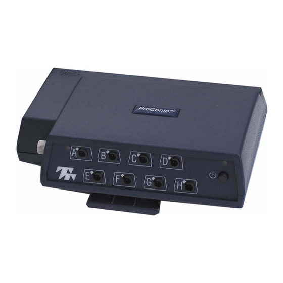
It has 8 protected pin sensor inputs with two channels sampled at 2048 s/s and six channels sampled at 256 s/s. The ProComp Infiniti encoder is able to render a wide and comprehensive range of objective physiological signs used in clinical observation and biofeedback. -
Page 9: Connecting The Encoder, Tt-Usb And Sensors
2. Insert one end of the fiber optic cable into the optical receiver jack on the rear face of the TT-USB Interface unit and the other into the optical transmitter jack on the front of the ProComp Infiniti encoder. Before inserting the cable, it may be necessary to loosen the jack heads by turning them counter-clockwise. - Page 10 (device drivers) where to find various pieces of hardware (devices). The driver for the TT-USB is installed along with the BioGraph Infiniti Main Application software. Therefore, before you could use the TT-USB with your ProComp Infiniti encoder the Biograph Infiniti Software must be installed on your computer.
- Page 11 Windows Explorer. Right-click on the My Computer icon and select Properties. Windows XP After clicking on the Hardware tab your screen should look like one of the two screens shown. Now click on Driver Signing. ProComp Infiniti Hardware Manual...
- Page 12 Windows 2000 Make sure that either Warn or Ignore is selected. Then click on OK. ProComp Infiniti Hardware Manual...
-
Page 13: Encoder Dip Switch Setup
ENCODER DIP SWITCH SETUP ProComp Infiniti encoder units have switches located on the it to the left of the belt clip. The switches can be flipped up and 0 (zero) position with the aid of a paper clip or small pointed front of the encoder facing up, verify that the switches are set software in use. -
Page 14: Battery Placement
Please note that a diagram of the correct battery polarity is embossed on the inside surface of the compartment. Closing The Compartment Slide the door back into the ProComp Infiniti case, gently pushing it in until you feel the click of the locking mechanism. Keeping An Eye On The Battery Level... -
Page 15: Compact Flash Setup
4. After the operation has concluded, you may remove the CF card from the reader. It is now ready for use in the encoder. However, you may wish to first initialize the Compact Flash card so that the encoder's date and time will be set (see below). ProComp Infiniti Hardware Manual... -
Page 16: Encoder Time Setting
Attention: Never use a CF card previously used with other devices for recording with the ProComp Infiniti. Thought Technology’s rebuilding process creates a single file on the CF card. Do not delete or overwrite this file, or attempt to create any other files on the Compact Flash once it has been formatted! If the Thought Technology format file is overwritten or deleted, the CF card may need to be re-formatted first to it’s original PC format, using the Format facility of your PC’s operating system. -
Page 17: Compact Flash Usage
1 and 2 seconds, then blinks slowly a number of times indicating an error code. The error code blink is repeated a total of 3 times. The CF LED then goes out. ProComp Infiniti Hardware Manual... -
Page 18: Start Recording
With removal a maximum of 1 second of recording will be lost. efer to software instructions for detailed information on transferring sessions from the Compact Flash card to the computer. ProComp Infiniti Hardware Manual... -
Page 19: Protected Pins
Shorter Length Of Fiber Optic Cable Although we ship the ProComp Infiniti system with one short and one long FO cable, the short length should only be used as a troubleshooting tool because it is too short and forces the ProComp Infiniti to stay too close to the computer. - Page 20 The TT-USB receives the data from the ProComp Infiniti encoder via the fiber optic and sends it on to the computer via the USB port. It has four connectors;...
-
Page 21: Sensors
EMG, we recommend that you use abrasive paste and conductive gel. Since body hair can form an insulating layer between the skin and the electrode surface, be careful not to place the electrodes over hairy areas. In some cases, shaving may be required. ProComp Infiniti Hardware Manual... -
Page 22: Sensor Care
Sensor Types The MyoScan and the MyoScan-Pro are the surface EMG (SEMG) sensors for the ProComp Infiniti device. SEMG is recorded from a sensor that is placed on the skin’s surface. The MyoScan-Pro sensors can be used on any input; the MyoScan-Pro automatically converts this signal to a root mean square (RMS) signal (an analog rectification is done inside the circuitry). -
Page 23: Measurement Unit
The typical waveform of an RMS SEMG signal is shown below: Changes in amplitude are directly proportional to the muscle's activity. Normal resting values are usually around 3 to 5 μV (they can be as low as .3 or even less for a profoundly relaxed muscle). ProComp Infiniti Hardware Manual... -
Page 24: Zeroing
ELECTROCARDIOGRAPHY (EKG) Sensor Type To record EKG on the ProComp Infiniti, use an EKG-Flex/Pro sensor. Although a signal can be detected by applying an EKG sensor, with Triode electrodes snapped on, anywhere on the client’s chest, using an extender cable and Uni-Gel electrodes greatly enhances the quality of the EKG signal. -
Page 25: Sensor Placement
When the electrodes are placed as described above, the typical signal should look similar to the illustration below. A sharply defined upward “R” spike is expected by the software in order to calculate the heart rate properly. ProComp Infiniti Hardware Manual... -
Page 26: Electroencephalography: Eeg Flex/Pro And Eeg-Z
ELECTROENCEPHALOGRAPHY: EEG FLEX/PRO AND EEG-Z Sensor Type To record EEG on the ProComp Infiniti, use an EEG-Flex/Pro or EEG-Z sensor. Unlike the EMG and EKG sensors, the EEG sensor will not be able to detect a good quality EEG signal without the use of extender leads and proper electrodes. -
Page 27: Impedance Checking
Impedance Checking When one or more EEG-Z sensors are plugged into the ProComp Infiniti encoder, and when the encoder is set up in ProComp Infiniti mode, it is possible to invoke the sensors’ impedance checking function. To do this, press and hold the power button for approximately 3 seconds, or until you see the blue LED blink quickly 2 times. -
Page 28: 10-20 Eeg Electrode Placement System
C3 is 20% of the full distance towards the left and C4, 20% of the full distance to the right. C3 and C4 are also very important points for EEG biofeedback. ProComp Infiniti Hardware Manual... -
Page 29: Typical Signal
T4, find F8 and T6. There are 10-20 placement maps that represent many more points. For most biofeedback applications, the ones listed above are all you should ever need to identify. Typical Signal SKIN CONDUCTANCE: SC FLEX/PRO Sensor Type The skin conductance sensor for ProComp Infiniti is called SC-Flex/Pro. ProComp Infiniti Hardware Manual... -
Page 30: Operating Principle
Typical Signal The type of signal recorded from a skin conductance sensor shows relatively rapid increases and slower decreases. PERIPHERAL TEMPERATURE Sensor Type To measure peripheral skin temperature with the ProComp Infiniti device, use the Temp-Flex/Pro sensor. ProComp Infiniti Hardware Manual... -
Page 31: Operating Principle
The BVP signal is a relative measure. It does not have a standard unit. From the BVP signal, the software can usually calculate heart rate and inter-beat interval. The amplitude of the BVP deviation can also be a useful measure. ProComp Infiniti Hardware Manual... -
Page 32: Sensor Placement
Measurement Unit The respiration signal is a relative measure of chest expansion. The ProComp Infiniti does not generate standard units of measure for respiration. From the raw signal waveform, the software is able to calculate the respiration rate and relative breath amplitude. If two sensors are used, it is possible to compute the difference in amplitude of expansion between the thorax and abdomen. -
Page 33: Typical Signal
Commonly, there is a fast rise that slows near the top of the breath and this is followed by a fast fall that slows near the end of the breath. The breathing pattern will alter itself as the person focuses on a task, talks or falls asleep. ProComp Infiniti Hardware Manual... -
Page 34: Goniometer Adapter
Manually enter the input Min and Max values and the corresponding output min and max values. It is also possible to enter the units of measure which will appear in generated reports. ProComp Infiniti Hardware Manual... -
Page 35: Force Adapter
FORCE ADAPTER Sensor Type A Force Sensor set up comprises two parts, the sensor and the adapter. The adaptor connects a Flexi force sensors to the encoder. Contact TTL or our authorized dealers for information on purchasing the sensors. Operating Principle A force sensor is sensitive to load applied to a small area of its surface. -
Page 36: Self-Calibration
Each channel’s gain and offset will be checked and set to be within the specifications listed at the back of this manual. To Perform A Self-Calibration: Ensure that the encoder’s DIP switches are set to ProComp Infiniti Mode. ProComp Infiniti Ensure that the encoder’s temperature is stable, and is close to the temperature at which you plan to use it. -
Page 37: Condition Code Summary
Condition Code Summary The ProComp Infiniti encoder communicates various conditions to the user by means of flashing its two LEDs. The following table summarizes what these flashes mean. Encoder Action or Mode Flash sequence Interpretation Normal operation BLUE – solid on Everything normal. -
Page 38: Reference
Reference TECHNICAL SUPPORT AND ORDER PLACING Returning Equipment Be sure to call for an authorization number (RA) before returning any equipment! Send the unit(s) postage prepaid and insured, with proof of purchase to one of the addresses below. If you are shipping from outside Canada or the USA to Canada, mark the package ‘Goods to be repaired - Made in Canada’... -
Page 39: Product Numbers & Accessories
Product Numbers & Accessories PROCOMP INFINITI ENCODER & SENSORS SA7500 PROCOMP INFINITI ENCODER SA7700 TT-USB T9305M EEG FLEX/PRO SENSOR T9305Z EEG-Z IMPEDANCE CHECKING SENSOR T9306M EKG FLEX/PRO SENSOR SA9308M BVP-FLEX/PRO BLOOD VOLUME PULSE SENSOR SA9309M SC-FLEX/PRO SKIN CONDUCTANCE SENSOR SA9310M... -
Page 40: Placing Orders
Placing Orders Outside USA Tel: (514) 489-8251 Fax: (514) 489-8255 In USA Toll-Free Tel: 1-800-361-3651 E-Mail: mail@thoughttechnology.com... -
Page 41: Specifications
Specifications MyoScan Pro EMG Sensor (SA9401M) Size (Approx.) 37mm x 37mm x 15mm (1.45” x 1.45” x 0.60”) Weight 25g (1 oz) Input Impedance 1,000,000MΩ in parallel with 10 pF Input Range 0 – 400μV , 0 – 1600μV Sensitivity <0.1μV Bandwidth 20Hz –... - Page 42 EEG-Z Sensor (SA9305Z) Size (Approx.) 37mm x 37mm x 12mm (1.45” x 1.45” x 0.45”) Weight (approx.) 25g (1oz) Input Impedance 10GΩ in parallel with 10pF Signal Input Range 0 –200μV Sensitivity <0.1μV CMRR >130dB Channel Bandwidth 2Hz – 1kHz ±0.3μV , ±5% of reading @10°C to 40°C Accuracy...
- Page 43 Voltage Isolator (SA9405) Size (Approx.) 95mm x 57mm x 32mm (3.75” x 2.25” x 1.25”) Weight 55g (2 oz) Input Impedance 1MΩ Input Range 0 – 200mV, 0 – 2V, 1.952V – 3.648V Bandwidth 0Hz – 40Hz Accuracy ±5% and ±1mV (0 – 200mV range) ±5% and ±10mV (0 –...
- Page 44 ProComp Infiniti Encoder (SA7500) Size (approx.) 130mm x 95mm x 37mm (5.1” x 3.7” x 1.5”) Weight (approx.) 200g (7oz) Power Source 4AA batteries, single use alkaline or NiMh Rechargeable Supply Voltage 3.6V – 6.5V (fiber optic), minimum 4.0V (Compact Flash)
-
Page 45: Index
Index Battery Placement, 14 Order Placing, 38 blood volume pulse, 31 Cable lengths, 8 Basic package, 8 Compact Flash, 14 ProComp Encoder Setup, 13 Connecting the Encoder Unit, 9 Protected Pins, 19 Connecting the Interface Unit, 9 Recording, 18 EEG sensor, 26 Repair Return Form, 47 EKG sensor, 24 Respiration sensor, 32... - Page 46 Warranty The P INFINITI system and all equipment including optional items are guaranteed to be free from defects in material and workmanship for 1 year from the date of purchase. In the unlikely event that repair is necessary, call Thought Technology Ltd. to receive a Return Authorization.
- Page 47 Repair Return Form Be sure to call for authorization before returning any equipment! Remove or copy this form and include it with the unit(s). Include copy of original invoice and return to the address in the Returning Equipment section. Name Company Address Phone No.
-
Page 48: Infiniti Hardware Copyright Notice
Infiniti hardware Copyright Notice This hardware contains proprietary embedded software code, which is the property of Thought Technology Ltd.; it is provided under a license agreement containing restrictions on use and disclosure and is also protected by copyright law. Reverse engineering of the software or the resulting output data stream is prohibited.
Need help?
Do you have a question about the Procomp Infiniti and is the answer not in the manual?
Questions and answers