Table of Contents
Advertisement
Advertisement
Table of Contents

Related Manuals for Skyworth LED 8M28A


Summary of Contents for Skyworth LED 8M28A
-
Page 1: Service Manual
SERVICE MANUAL 8M28A CHASSIS Design and specifications are subject to change without prior notice. (Only Referrence) SERVICE MANUAL 8M28A Description: SKYWORTH MODEL. Brand Name: JOB NO. SIZE:A5 2012-4-28 Engineering Dept: Artwork By: Date: Checked By: Date: Approved By: Date:... - Page 2 Content--------------------------------------------------------------2 11-17 19-20 21-29 30-47 48-51 52-59...
- Page 3 LED 8M26A...
- Page 4 PAL SECAM / BG DK PAL / I NTSC / M 44.25MHz ~ 140.25MHz VHF LOW K1~S6 147.25MHz ~ 423.25MHz VHF HIGH S7~S36 431.25MHz ~ 863.25MHz S37~DS57 Asia\Europe TOSHIBA CODE Component...
- Page 5 For 22” LED For 24” LED For 32” LED...
- Page 6 (24 inches is 4 ohm) (24 inches is 3W)
- Page 7 (26inches is 8 ohm) 12000...
- Page 8 Standard Standard Spanish...
- Page 9 30000...
-
Page 11: Connection Diagram
AP1117 1A LOW DROPOUT POSITIVE ADJUSTABLE OR FIXED-MODE REGULATOR Typical Application Circuit 10uF 10uF 2.5V/1A 3.3V/1A 22uF 22uF Tab is V Tab is V ( 5V/3.3V fixed output ) ( 5V/2.5V ADJ output ) Note: Connection Diagram 3 PIN SOT223 3 PIN TO252 / TO263 ( Top View ) ( Top View ) -
Page 12: Block Diagram
AP1117 1A LOW DROPOUT POSITIVE ADJUSTABLE OR FIXED-MODE REGULATOR Block Diagram 1.25V CURRENT LIMIT (FIXED) Thermal Shutdown Pin Descriptions NAME PIN # FUNCTION A resistor divider from this pin to the V pin and ground sets the output voltage Adj (GND) (Ground only for Fixed-Mode). -
Page 13: Pin Configurations
A1semi 1A Fixed and Adjustable Low AS1117 Electronics Ltd Dropout Linear Regulator(LDO) Pin Configurations L Package U Package (SOT-223) (SOT-89) INPUT INPUT OUTPUT OUTPUT ADJ/GND ADJ/GND T Package R Package (TO-220) (TO-252) INPUT INPUT OUTPUT OUTPUT ADJ/GND ADJ/GND S Package (TO-263) INPUT OUTPUT... - Page 14 A1semi 1A Fixed and Adjustable Low AS1117 Electronics Ltd Dropout Linear Regulator(LDO) Functional Block Diagram INPUT Thermal Shutdown OUTPUT GND (Fixed Output) ADJ (Adjustable Output) Figure 3. Functional Block Diagram of AS1117 http://www.a1semi.com A1 SEMI ELECTRONICS LTD.
-
Page 15: General Description
AOZ1051PI EZBuck™ 3 A Synchronous Buck Regulator General Description Features The AOZ1051PI is a high efficiency, easy to use, 3 A 4.5 V to 18 V operating input voltage range synchronous buck regulator. The AOZ1051PI works from Synchronous Buck: 70 m internal high-side switch 4.5 V to 18 V input voltage range, and provides up to 3 A and 40 m internal low-side switch (at 12 V) -
Page 16: Pin Configuration
AOZ1051PI Ordering Information Part Number Ambient Temperature Range Package Environmental AOZ1051PI -40 °C to +85 °C EPAD SO-8 Green Product AOS Green Products use reduced levels of Halogens, and are also RoHS compliant. Please visit www.aosmd.com/web/quality/rohs_compliant.jsp for additional information. Pin Configuration PGND (LX) AGND... - Page 17 AOZ1051PI Block Diagram Internal UVLO 5V LDO & POR Regulator ISen Reference Softstart – & Bias ILimit 5μA Level 0.8V Shifter EAmp – Control Comp – Logic Driver COMP 500kHz Oscillator PGND AGND Absolute Maximum Ratings Recommended Operating Conditions Exceeding the Absolute Maximum Ratings may damage the The device is not guaranteed to operate beyond the Maximum device.
- Page 18 SY8086 High Efficiency 1.4MHz, 1A Synchronous Step Down Regulator Preliminary Specification General Description Features • Low R The SY8086 is a high-efficiency 1.4MHz synchronous for internal switches (top/bottom): DS(ON) 250m Ω /200m Ω step-down DC-DC regulator ICs capable of delivering •...
- Page 19 SY8086 Pinout (top view) SOT23-5 Top mark: BE xyz (Device code: BE, x=year code, y=week code, z= lot number code) Pin Name Pin Number Pin Description Enable control. Pull high to turn on. Do not float. Ground pin Inductor pin. Connect this pin to the switching node of inductor Input pin.
-
Page 20: Ic Block Diagram
IC Block Diagram U10(LCDTV CONTROLLER WITH VIDEO ECODE)MST6E181VS PIN DIAGRAM (MST6E181VS) -13-... - Page 21 "pdfFactory Pro" www.fineprint.cn...
- Page 22 "pdfFactory Pro" www.fineprint.cn...
- Page 23 "pdfFactory Pro" www.fineprint.cn...
- Page 24 "pdfFactory Pro" www.fineprint.cn...
- Page 25 "pdfFactory Pro" www.fineprint.cn...
- Page 26 "pdfFactory Pro" www.fineprint.cn...
- Page 27 "pdfFactory Pro" www.fineprint.cn...
- Page 28 "pdfFactory Pro" www.fineprint.cn...
- Page 29 "pdfFactory Pro" www.fineprint.cn...
- Page 30 "pdfFactory Pro" www.fineprint.cn...
- Page 31 "pdfFactory Pro" www.fineprint.cn...
- Page 32 "pdfFactory Pro" www.fineprint.cn...
- Page 33 "pdfFactory Pro" www.fineprint.cn...
- Page 34 "pdfFactory Pro" www.fineprint.cn...
- Page 35 "pdfFactory Pro" www.fineprint.cn...
- Page 36 "pdfFactory Pro" www.fineprint.cn...
- Page 37 IC Block Diagram -15-...
- Page 39 8M28A/S Factory Adjust Menu (V0.0) 1. Description Enter factory mode: Open source menu, and then press digital button “3”, “1”, “9” , “5” in turns to enter the factory menu. Press ↑ and ↓ button to choose the item, press OK button enter the submenu, press MENU to ruturn to , press ←...
- Page 40 factory, select “AUTO ADC” item in the “ADC CALIBRATION” menu, press → button to begin auto adjust. When it is finish, it will show “OK” or “FAILE”. If “FAILE” is showed, you need to try again. NOTE: YPBPR ADC need to do twice by use 576P and 720P signal separate.
- Page 41 White balance: Enter factory mode, enter “W/B ADJUST” item, you can adjust white balance in this menu. Over scanning: Enter factory mode, enter “Panel SETTING” submenu, enter “OVERSCAN” submenu, you can adjust the over scan in these menu. OutFactory reset: Enter factory mode, enter “SYSTEM SETTING”...
- Page 42 Update software (by USB): Copy the new software (name by “MERGE.bin”) to the root directory of USB drive. Plug the drive to the USB2 socket (if there are two USB socket, make sure you use the socket 2). Enter factory, select “Software Update (USB)”...
- Page 43 2. More information FACTORY MENU Default Value Remark ADC ADJUST MODE Select source R-GAIN Red gain G-GAIN Green gain B-GAIN Blue gain R-OFFSET Red offset G-OFFSET Green offset B-OFFSET Blue offset AUTO ADC Auto ADC calibration W/B ADJUST MODE Select source TEMPERATURE Select Neutral/Warm/Cool/Personal R-GAIN...
- Page 44 LVDS BIT 8BitPanel PWMFREQUENCY PWM DUTY OVERSCAN OVERSCAN_RESLUTION HPOSITION Horizontal position VPOSITION Vertical position HSIZE Horizontal size VSIZE Vertical size SYSTEM SETTING FACHOTKEY Factory hot key enable TTX BRI Logo enable WHILE PATTERN NO USED POWER REMIND Preset the no signal standby time BULE SCREEN Blue or Black screen when no signal VIDEO AGC...
- Page 45 Channel Preset Reset channel to default NO SIGNAL MUTE AMP OUT FAC SOUND SYS AGC GAIN LANGUAGE SETTING 繁体中文 S-CHINESE 西班牙语 SPANISH 法语 FRENCH 葡萄牙语 PORTUGUESE 俄罗斯语 RUSSIAN 繁体中文 BIG CHINESE 保加利亚语 BULGARIAN 斯洛伐克语 SLOVAK 芬兰语 FINNISH 印度尼西亚 INDONESIA 阿拉伯语 ARABIC 阿拉伯语...
- Page 46 SCART HDMI1 HDMI2 HDMI3 YPbPr1 USB1 USB2 AGALOG CURVE MODE PICTURE MODE BRIGHTNESS CURVE CONTRAST CURVE SATURATION CURVE HUE CURVE SHARPNESS CURVE VOLUME CURVE BACKLIGHT HOTEL FUNCTION HOTEL MODE Hotel mode enable IR LOCK LOCAL KEY LOCK USER SETTING SAVE VOLUME FIXED POWER ON VOL VALUE...
- Page 47 MAX VOLUME POWER ON SOURCE SCALE LOCK CHANNEL SEARCH LOCK OTHER OPTION LVDS and DDR frequency setting UART DEBUG NO USED SPECIAL NO USED VIF1 VIF1 VIF setting VIF2 VIF-AGC-VGA-BASE item is used adjust TUNER AGC VIF3 POWER ON LOGO NONE Teletext NO USED...
- Page 48 Instruction Manual 19E66 Size:A5 Description: MANUAL(8M28A) SKYWORTH Job No. Brand Name: 19E66 MODEL: P/No. REV:0 Scale: Engineering Dept: 2012-04-26 Artwork By: Date: Checked By: Date: Approved By: Date:...
-
Page 49: Table Of Contents
CONTENT CONTENT ......................1 WARNING AND PRECAUTION ................ 2-3 INTRODUCTION, FUNCTIONS AND FEATURES ..........4 PREPARATION ....................5 Positioning The TV Set ................. 5 Antenna And Power Connections ..............5 Inserting Batteries In The Remote Control Handset ........5 EXTERNAL SCHEMATIC AND INSTALLATION ..........6-11 Front Panel .................... -
Page 50: Warning And Precaution
WARNING AND PRECAUTION Read all of the instructions before operating the set. Keep these instructions well for later use. PRODUCT The ventilation should not be impeded by covering the ventilation openings with items, such as newspaper, table-cloths, curtains, etc. Do not push any objects of any kind into this unit through the cabinet slots as they could touch the current carrying parts or short-circuit parts, resulting in fire, electric shock, or damage to the unit. - Page 51 WARNING AND PRECAUTION USE ENVIRONMENT Do not install this equipment in a confined space such as a book case or similar unit. To prevent injury, this apparatus must be securely attached to the wall mount fastened on the wall. Place the set on a place that allows good ventilation. Do not use the set near damp, and cold areas, protect the set from overheating.
-
Page 52: Basic Function
INTRODUCTION, FUNCTIONS AND FEATURES BRIEF INTRODUCTION: Thanks for your purchase of our digital high-definition LED television! This product with diverse functions is designed to fulfill the optimum requirements from commercial, industrial and household uses. LED television possesses the display function of both TV and PC. It features advanced picture performance, smaller in size and lighter in weight, meanwhile, consumes less power and makes no radiation. -
Page 53: Preparation
PREPARATION Insering Batteries In The Positioning The TV Set Remote Control Handset Install Display on solid horizontal surface such as a table or desk. For ventilation, leave a space Remove the battery cover. of at least 10cm free all around the set. To prevent any fault and unsafe situations, please Insert two AAA Alkaline or equivalent batteries. -
Page 54: External Schematic And Installation
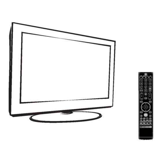
EXTERNAL SCHEMATIC AND INSTALLATION Front Panel Note: The graphics are for representation only. 1.Power Button 2.Power Indicator / Remote Sensor 3.Speakers 4.Program Up/Down Button 5.Volume Up/Down Button 6.Menu Button 7.Source Button 8.Standby Button... -
Page 55: Back Panel
EXTERNAL SCHEMATIC AND INSTALLATION Back Panel Note: The graphics are for representation only. USB2 HDMI IN PC IN RF IN AV IN 5V 500mA VIDEO AUDIO IN 1. USB1\USB2: USB port. 2. HDMI IN:Connect HDMI input signal from signal source such as DVD. 3. -
Page 56: Antenna/Cable Connection
EXTERNAL SCHEMATIC AND INSTALLATION Antenna /Cable Connection There are two kinds of antenna in use. VHF TV ANTENNA TWO KINDS OF ANTENNA UHF TV ANTENNA To TV VHF/UHF No need to install adapter ANTENNA jack (Note 1) U/V MIXER COAXIAL ANTENNA Need to install adapter VHF/UHF (Note 2) -
Page 57: Remote Control
EXTERNAL SCHEMATIC AND INSTALLATION Remote Control 1. POWER( Press to turn the TV on or off(standby). 2.MUTE( Press to mute or restore the volume. 3. Program Select (0-9) Press to select the TV channel directly. 4.RETURN Button Press to return to the previously viewed channel. 5.INFO. - Page 58 EXTERNAL SCHEMATIC AND INSTALLATION Remote Control Control Buttons Play & Pause ( Press to pause playback, press again to continue playback. Stop ( Press the stop button to exit full-screen playback, access to the preview. Fast Backward Button( Press to fast reverse. Fast Forward ( Press to fast forward.
- Page 59 EXTERNAL SCHEMATIC AND INSTALLATION Remote Control 19.TEXT BUTTONS(Option) Press to enter the teletext menu. INDEX Press this button to display index page. HOLD Press to hold the teletext page on screen without update and changes. Press again to release the hold state. When not in teletext mode, press this button to freeze the picture display.
-
Page 60: Menu Control
MENU CONTROL This section explains the menus of your TV. Each menu is outlined and detailed to help you get the most from your TV. Basic Operation 1. Press MENU on the remote control or on the TV key panel to display the main menu. 2. -
Page 61: Sound Settings
MENU CONTROL Neutral: Keep the original white Warm: Red Personal: The user may customize the color temperature.(Red/Green/Blue). Cold: Blue. Display Mode Press " " or " " to select display mode including: Panorama, Movie, Caption, 16:9, 4:3 and Auto. Note: In PC channel only 16:9 and 4:3 display mode can be selected. In HDMI channel including: Panorama, Just-Scan, Movie, Caption, 16:9, 4:3 and Auto display mode can be selected. -
Page 62: Installation Settings
MENU CONTROL Installation Settings Note: These settings are only available in TV mode. Channel No. INSTALLATION Sets the received TV channel No. Channel No. Color System Colour system Sound System Selects colour system. Auto Search Manual Search Fine Tuning 208.25MHz Sound system Channel Skip Selects sound system. -
Page 63: Setup Settings
MENU CONTROL Setup Settings OSD Language SETUP Select you desired OSD language. OSD Language English TTX Language TTX Language Russian Select the desired Teletext language: West Europe / Nicam Mono East Europe / Russian / Arabic. User Reset Sleep Timer NICAM (Option) "... -
Page 64: Pc Settings
MENU CONTROL PC Settings Note: These settings are only available in PC mode. when you connect VGA cable to the jacks of PC and select the signal source as "PC" the screen menu will be activated. You can use the function to adjust the display setting automatically or manualiy. -
Page 65: Usb Control
USB CONTROL Gentle Reminder When Using The USB Player 1.Some USB storage devices may not be compatible to operate smoothly with this TV. 2.Back up all of the data in the USB storage device in case if data was lost due to unexpected accident. -
Page 66: Remote Control
USB CONTROL Remote Control 1.USB buttons Into the SOURCE to select the USB menu, press OK to enter the USB menu. 2.Fast Backward buttons( Fast reverse while playback. 3.Fast Forward buttons( Fast forward while playback. 4.Previous buttons( Press to return to the previous chapter /track/photo. -
Page 67: Video Menu
USB CONTROL Video Menu 1.Press [ ] / [ ] to select VIDEO. Press [ OK ] to enter. Return 2.Press [ ] / [ ] to select the desired drive VIDEO and press [ OK ] to enter. 3inl. 3.Press [ ] / [ ] to select the desired folder... -
Page 68: Music Menu
USB CONTROL Music Menu 1.Press [ ] / [ ] to select MUSIC. Press [ OK ] to enter. Return 2.Press [ ] / [ ] to select the desired drive MUSIC and press [ OK ] to enter. Super Star.mp3 3.Press [ ] / [ ] to select the desired folder... -
Page 69: Photo Menu
USB CONTROL Photo Menu 1.Press [ ] / [ ] to select PHOTO. Press [ OK ] to enter. Return 2.Press [ ] / [ ] to select the desired drive and press [ OK ] to enter. PHOTO Picture01.jpeg 3.Press [ ] / [ ] to select the desired folder... -
Page 70: Text Menu
USB CONTROL Text Menu 1.Press [ ] / [ ] to select TEXT. Press [ OK ] to enter. Return 2.Press [ ] / [ ] to select the desired drive Please ensure that the text TEXT and press [ OK ] to enter. file is saved in an encoding standard (eg.Unicode). -
Page 71: Troubleshooting
TROUBLESHOOTING NO PICTURE, NO SOUND SNOWY DOTS AND INTERFERENCE If the antenna is located in the fringe area of a 1. Check if the fuse or circuit breaker is working. television signal where the signal is weak, the 2. Plug another electrical device into the outlet to picture may be marred by dots. -
Page 72: Specifications
SPECIFICATIONS Screen size - diagonal: 47cm Screen resolution: 1366 X768 Audio output power (L+R): 3W + 3W Working voltage: 100-240V~ 50/60Hz Rated power consumption: Dimensions (W x D x Hmm): 459.2 X 130 X 338mm Net weight: 3.4Kg Environment: Working temperature: 5 C~35 C Working humidity: 20%~80% Storage temperature: -15 C~45 C Storage humidity: 10%~90%... - Page 73 Service Flow Chart -48-...
- Page 74 Service Flow Chart -49-...
- Page 75 Service Flow Chart -50-...
- Page 76 Service Flow Chart -51-...
- Page 77 BH3544 BH3544 47uF/16V 47uF/16V R211 R211 3.3K 3.3K R331 NC/4.7K R331 NC/4.7K R209 3.3K R209 3.3K <OrgName> <OrgName> <OrgName> OP-MUTE SKYWORTH R330 4.7K R330 4.7K Title Title Title MUTE MST6M161LG&181VG&182VG MST6M161LG&181VG&182VG MST6M161LG&181VG&182VG 3904 3904 Size Size Size Document Number Document Number...
- Page 78 0.1u +5V_Tuner L116 L116 47uH 47uH +5V_Normal C243 C243 CA18 CA18 0.1u 0.1u 470uF/16V 470uF/16V <OrgName> <OrgName> <OrgName> SKYWORTH Title Title Title MST6M161LG&181VG&182VG MST6M161LG&181VG&182VG MST6M161LG&181VG&182VG Size Size Size Document Number Document Number Document Number MST6M161LG&181VG&182VG MST6M161LG&181VG&182VG MST6M161LG&181VG&182VG V1.0 V1.0 V1.0...
- Page 79 USB1_D1+_in USB1_D1+_in USB1_D1-_in USB1_D1-_in +5V_USB1 +5V_USB1 AV-OUT DIP2x5PIN DIP2x5PIN SP_AINL PRE_AMP_L SP_AINR PRE_AMP_R EAR_MUTE EAR_MUTE <OrgName> <OrgName> <OrgName> SKYWORTH Title Title Title MST6M161LG&181VG&182VG MST6M161LG&181VG&182VG MST6M161LG&181VG&182VG Size Size Size Document Number Document Number Document Number MST6M161LG&181VG&182VG MST6M161LG&181VG&182VG MST6M161LG&181VG&182VG V1.0 V1.0 V1.0...
- Page 80 VGA-VS R148 R148 VGA_VS VGA_VS VGA-SDA UART-TX R217 R217 R229 R229 UART-TX VGA-SCL UART-RX UART-RX <OrgName> <OrgName> <OrgName> SKYWORTH Title Title Title MINI8M48 MINI8M48 MINI8M48 Size Size Size Document Number Document Number Document Number MST6M161LG&181VG&182VG MST6M161LG&181VG&182VG MST6M161LG&181VG&182VG V1.0 V1.0 V1.0...
- Page 81 +5V_USB1 USB1_D1-_in USB1_D- USB1_D1-_in USB1_D- USB1_D1+_in USB1_D+ USB1_D1+_in USB1_D+ CA110 CA110 100uF/16V 100uF/16V 0.1uF 0.1uF <OrgName> <OrgName> <OrgName> SKYWORTH Title Title Title MST6M161LG&181VG&182VG MST6M161LG&181VG&182VG MST6M161LG&181VG&182VG Size Size Size Document Number Document Number Document Number MST6M161LG&181VG&182VG MST6M161LG&181VG&182VG MST6M161LG&181VG&182VG V1.0 V1.0 V1.0...
- Page 82 HOTPLUG +3.3V_Normal +3.3V_Normal HDMI2_5V R168 R168 1K/NC 1K/NC HPD_SINK 4.7K 4.7K HDMI_HP1 HDMI_HP1 MMBT3904 MMBT3904 <OrgName> <OrgName> <OrgName> SKYWORTH Title Title Title MINI8M48 MINI8M48 MINI8M48 Size Size Size Document Number Document Number Document Number MST6M161LG&181VG&182VG MST6M161LG&181VG&182VG MST6M161LG&181VG&182VG V1.0 V1.0 V1.0...
- Page 83 4.7K 4.7K 4.7K R126 R126 TUNER_SCL <OrgName> <OrgName> <OrgName> C153 C153 C154 C154 C155 C155 4.7K 4.7K R129 R129 SKYWORTH 2D/3D 0.1uF 0.1uF 0.1uF 0.1uF 2.2uF 2.2uF 4.7K 4.7K GPIO53 Chip Config Title Title Title MST6M161LG&181VG&182VG MST6M161LG&181VG&182VG MST6M161LG&181VG&182VG Size Size...
- Page 84 VOUT = Vref*(1 + R25/R23 ) + Iadj*R25 0.1UF 0.1UF 100K 100K 0.1uF 0.1uF 12VST_ON/OFF R19 10K R19 10K 备注: 1:U5是为DDR提供电源,MST6M182VG内包DDR2,输出为1.8V。 <OrgName> <OrgName> <OrgName> SKYWORTH Title Title Title MST6M161LG&181VG&182VG MST6M161LG&181VG&182VG MST6M161LG&181VG&182VG Size Size Size Document Number Document Number Document Number Custom Custom Custom MST6M161LG&181VG&182VG...
Need help?
Do you have a question about the LED 8M28A and is the answer not in the manual?
Questions and answers