Table of Contents
Advertisement
Quick Links
Advertisement
Table of Contents
Troubleshooting

Related Manuals for Huansong UTV 700 2009

Summary of Contents for Huansong UTV 700 2009
- Page 1 HUANSONG UTV 700 SERVICE MANUAL 2009...
-
Page 2: Table Of Contents
CONTENT DESCRIPTION AND MACHINE IDENTIFICATION IDENTIFICATION CODE ………………………………………………………………… Frame No. ……………………………………………………………………………… Engine No. ……………………………………………………………………………… CHAPTER 1 GENERAL INFORMATION MANUAL ORGANIZATION………………………………………………………………… WATNINGS ,CAUTIONS AND NOTES…………………………………………………… SAFETY ……………………………………………………………………………………… 1-3 Handing gasoline safely ……………………………………………………………… Cleaning parts…………………………………………………………………………… Warning labels…………………………………………………………………………… SERIAL NUMBERS………………………………………………………………………… FASTENERS………………………………………………………………………………… Torque specifications…………………………………………………………………… Self-locking fasteners…………………………………………………………………... - Page 3 Socket wrenches, ratchets and handles…………………………………………… 1-13 Impact drivers…………………………………………………………………………… 1-14 Allen wrenches………………………………………………………………………… 1-14 Torque wrenches………………………………………………………………………… 1-14 Torque adapters………………………………………………………………………… 1-15 Pliers……………………………………………………………………………………… 1-16 Snap ring pliers………………………………………………………………………… 1-16 Hammers………………………………………………………………………………… 1-16 Ignition grounding tool………………………………………………………………… 1-17 PRECISION MEASURING TOOLS……………………………………………………… 1-17 Feeler gauge…………………………………………………………………………… 1-18 Calipers…………………………………………………………………………………… 1-18 Micrometers……………………………………………………………………………… 1-19 Adjustment………………………………………………………………………………...
- Page 4 Preparing the Motorcycle for Storage………………………………………………… 1-31 Returning the Motorcycle to Service…………………………………………………… 1-32 1-33 CHAPTER TWO TROVBLESHOOTING………………………………………………… 1-34 ENGINE PRINCIPLES AND OPERATING REQUIREMENTS………………………… STARTING THE ENGINE ………………………………………………………………… 1-34 Engine is cold …………………………………………………………………………… 1-34 Engine is warm…………………………………………………………………………… 1-34 Starting the engine after a fall or after the engine stalls……………………………… 1-35 Flooded engine……………………………………………………………………………...
- Page 5 Low engine compression……………………………………………………………… 1-45 High engine compression……………………………………………………………… 1-46 Engine overheating (Cooling System) ……………………………………………… 1-46 Engine overheating (Engine) ………………………………………………………… 1-46 Preignition………………………………………………………………………………… 1-47 Detonation………………………………………………………………………………… 1-47 Power Loss Engine Noises……………………………………………………………… 1-47 ENGLNE LUBRICATION…………………………………………………………………… 1-48 High Oil Consumption or Excessive ……………………………………………………… 1-48 Exhaust smoke…………………………………………………………………………… 1-48 1-48 Low oil pressure…………………………………………………………………………...
- Page 6 1-58 Soft or Spongy Brake Lever or Pedal………………………………………………… 1-60 Brake drag……………………………………………………………………………… 1-60 Hard Brake Lever or Pedal Operation………………………………………………… 1-60 Hard Brake Lever or Pedal Operation………………………………………………… 1-61 Brake Squeal or Chatter………………………………………………………………… 1-61 Leaking brake caliper…………………………………………………………………… 1-61 Leaking master cylinder………………………………………………………………… CHAPTER 2 SPECIFICATIONS HOW TO USE CONVERSION TABLE OF UNIT………………………………………...
- Page 7 Adjusting the starter cable …………………………………………………………… 3-7 Checking the spark plug……………………………………………………………… Checking the ignition timing ………………………………………………………… Measuring the compression pressure ……………………………………………… 3-10 Checking the engine oil level ……………………………………………………… 3-11 Changing the engine oil ……………………………………………………………… 3-12 CHASSIS Cleaning the air filter ………………………………………………………………… 3-15 Checking the coolant level ……………………………………………………………...
- Page 8 …………………………………………………………… 3-43 Changing the headlight bulb ………………………………………………………… 3-44 Changing the tail/brake light bulb CHAPTER 4 ENGINE ENGINE NOTE …………………………………………………………………………… ENGINE REMOVAL………………………………………………………………………… 4-2 CYLINDER HEAD AND CYLINDER HEAD COVER ………………………………… ROCKER ARMS AND CAMSHAFT …………………………………………………… 4-10 VALVES AND VALVE SPRINGS ……………………………………………………… 4-16 CYLINDER AND PISTON…………………………………………………………………...
- Page 9 DIRECTION SYSTEM The structure of the steering…………………………………………………………… The structure of steering wheel part…………………………………………………… 5-6 Diassembling the parts of the steering wheel ………………………………………… The structure of steering wheel part …………………………………………………… 5-8 Diassembling the steering column parts……………………………………………… Checking and service the steering column parts …………………………………… 5-10 Steering drive axle ………………………………………………………………………...
- Page 10 Checking the joints……………………………………………………………………… 5-55 Checking the differential gear ………………………………………………………… 5-56 Installing the front bridge parts………………………………………………………… 5-57 Rear bridge ……………………………………………………………………………… 5-58 REVERSE MECHANISM PARTS ……………………………………………………… 5-64 Adjusting reverse mechanism parts ………………………………………………… 5-67 Checking and service of reverse mechanism………………………………………… 5-67 SUSPENSION……………………………………………………………………………… 5-68 Front Suspension and arm ……………………………………………………………...
- Page 11 CHECKING THE SWITCH ……………………………………………………………… Checking the switch…………………………………………………………………… Checking the switch continuity ……………………………………………………… CHECKING THE BULBS AND BULB SOCKETS …………………………………… IGNITION SYSTEM ……………………………………………………………………… TROUBLESHOOTING …………………………………………………………………… ELECTRIC STARTING SYSTEM ……………………………………………………… 6-11 CIRCUIT DIAGRAM ……………………………………………………………………… 6-11 TROUBLESHOOTING …………………………………………………………………… 6-12 STARTER MOTOR ……………………………………………………………………… 6-15 Checking the starter motor ……………………………………………………………...
- Page 12 CHAPTER 7 TROUBLESHOOTING STARTING FAILURE/HARD STARTING………………………………………………… 7-1 Fuel system ……………………………………………………………………………… Electrical system ………………………………………………………………………… 7-1 Compression system …………………………………………………………………… POOR IDLE SPEED PERFORMANCE ………………………………………………… Poor idle speed performance…………………………………………………………… POOR MEDIUM AND HIGH-SPEED PERFORMANCE ……………………………… Poor medium and high-speed performance…………………………………………… 7-3 FAULTY GEAR SHIFTING………………………………………………………………… Shift lever does not move ………………………………………………………………...
-
Page 13: Description And Machine Identification
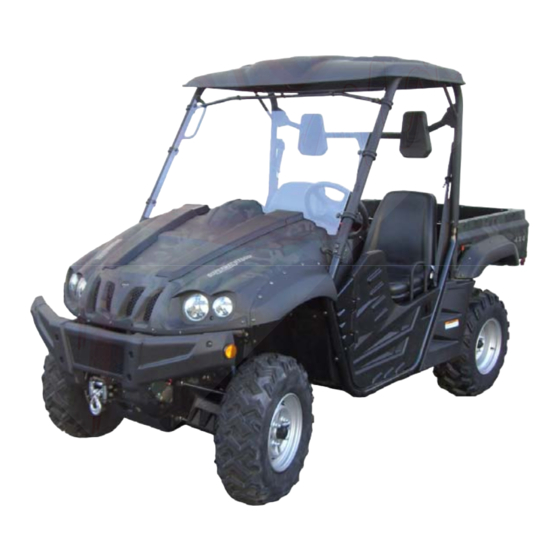
GENERAL INFORMATION DESCRIPTION AND MACHINE IDENTIFICATION 1. Headlights 2. Front shock absorber assembly adjusting ring 3. Brake fluid reservoir 4. Air filter element (engine and air intake duct) 5. V-belt case 6. Driver seat 7. Driver seat belt 8. Spark plug 9. -
Page 14: Identification Code
GENERAL INFORMATION IDENTIFICATION CODE Frame No. Frame No. is carved in the lower right side of Figure. Engine No. Engine NO. is carved on the right side of the engine, Figure. -
Page 15: Manual Organization
GENERAL INFORMATION CHAPTER ONE GENERAL INFORMATION The text provides complete information on maintenance,tune-up repair and overhaul,Hundreds of photographs and illustrations created during the complete disassembly of UTV guide the reader through every job,All procedures are in step-by-step format and designed for the reader who may be working on the UTV for the first time MANUAL ORGANIZATION A shop manual is a tool and, as in all Clymer manuals, the chapters are thump tabbed for easy... -
Page 16: Handing Gasoline Safely
GENERAL INFORMATION Do not operate the utility terrain venires in an enclosed area venires The exhaust gasses contain carbon monoxide. an odorless, colorless and tasteless poisonous gas. Carbon monoxide levels build quickly in small enclosed areas and can cause unconsciousness and death in a short time. Make sure to properly ventilate the work area or operate the UTV side Never use gasoline or any extremely flammable liquid to clean parts. -
Page 17: Cleaning Parts
GENERAL INFORMATION sparks or where someone is smoking .Gasoline vapor is heavier than air, it collects in low areas and is more easily ignited than liquid gasoline. Allow the engine to cool completely before working on any fuel system component. Do not store gasoline in glass containers. -
Page 18: Serial Numbers
GENERAL INFORMATION SERIAL NUMBERS Serial and identification numbers are stamped on various locations on the frame, engine and carburetor body. Record these numbers in the Quick Reference Data section in the front of the manual. Have these numbers available when ordering parts. FASTENERS Proper fastener selection and installation is important to ensure the motorcycle operates as designed and can be serviced efficiently. -
Page 19: Washers
GENERAL INFORMATION Washers The two basic types of washers are flat washers and lock washers. Flat washers are simple discs with a hole to fit a screw or bolt. Lock washers are used to prevent a fastener from working loose. Washers can be used as spacers and seals. -
Page 20: Shop Supplies
GENERAL INFORMATION into place Observe the following when installing snap rings: Remove and install snap rings with snap rings pliers. Refer to Basic Tools in this chapter In some applications. it may be necessary to replace snap rings after removing them Compress or expand snap rings only enough to install them. -
Page 21: Greases
GENERAL INFORMATION Viscosity is an indication of the oil’s thickness. Thin oils have a lower number while thick oil have a higher number. Engine oils fall into the 5-to50-weight range for single-grade oils. Most manufactures recommend multi-grade oil. These oils perform efficiently across a wide range of operating conditions. -
Page 22: Cleaners Degreasers And Solvents
GENERAL INFORMATION Cleaners, Degreasers and Solvents Many chemicals are available to remove oil, grease and other residue from the motorcycle UTV. Before using cleaning solvents, consider how they will be used and disposed of , particularly if they are not water-soluble. Local ordinances may types of cleaning chemicals. Refer to Safer in this chapter. Use brake parts cleaner to brake system components. -
Page 23: Basic Tools
GENERAL INFORMATION fastener to work loose from vibration or hear expansion and contraction. Some thread locking compound sparingly. Excess fluid can run into adjoining parts. CAUTION Thread locking compounds are anaerobic and will stress, crack and attack most plastics. Use caution when using These products in areas where there are plastic components. -
Page 24: Wrenches
GENERAL INFORMATION specifications. Poor quality or damaged Phillips screwdrivers can back out (cam out) and round over the screw head. In addition. Weak or soft screw materials can make removal difficult. The best type of screwdriver to use on Phillips screw is the ACR Phillips II screwdriver, patented by the horizontal anti-cam out ribs found on the driving faces or flutes of the screwdriver’s tip (figure 4). -
Page 25: Adjustable Wrenches
GENERAL INFORMATION open-end on the other. This combination makes it a convenient tool. Adjustable wrenches An adjustable wrench or Crescent wrench (Figure 6) can fit nearly any nut or bolt head that has clear access around its entire perimeter. An adjustable wrench is best used as a backup wrench to keep a large nut or bolt from turning while the other end is being loosened or tightened with a box-end or socket wrench. -
Page 26: Impact Drivers
GENERAL INFORMATION most convenient tool for fastener removal and installation Impact Drivers An impact driver provides extra force for removing fasteners by converting the impact of a hammer into a turning motion. This makes it possible to remove stubborn fasteners without damaging them. Impact drivers and interchangeable bits (Figure 10) are available from most tool suppliers. -
Page 27: Torque Adapters
GENERAL INFORMATION torque wrenches in cases or separate padded drawers within a toolbox. Follow the manufacturer’s instructions for their care and calibration. Torque Adapters Torque adapters or extensions extend or reduce the reach of a torque wrench. The torque adapter shown in (Figure 13) is used to tighten a fastener that cannot be reached because of the size of the torque wrench head, drive, and socket. -
Page 28: Pliers
GENERAL INFORMATION Pliers Pliers come in a wide range of types and sizes. Pliers are useful for holding, cutting, bending, and crimping. Do not use them to turn fasteners. Figure 15 and Figure 16 show several types of useful pliers. Each design has a specialized function. -
Page 29: Ignition Grounding Tool
GENERAL INFORMATION condition and the handle is not cracked. Select the correct hammer for the job and make sure to strike the object squarely. Do not use the handle or the side of the hammer to strike an object. Ignition Grounding Tool Some test procedures require turning the engine over without starting it. -
Page 30: Feeler Gauge
GENERAL INFORMATION Feeler Gauge Use feeler or thickness gauges (Figure19) for measuring the distance between two surfaces. A feeler gauge set consists of an assortment of steel strips of graduated thickness. Each blade is marked with its thickness. Blades can be of various lengths and angles for different procedures. -
Page 31: Micrometers
GENERAL INFORMATION Micrometers A micrometer is an instrument designed for linear measurement using the decimal divisions of the inch or meter (Figure 22). While there are many types and styles of micrometers, most of the DECIMAL PLACE VALUES* Indicates 1/10 (one tenth of an inch or millimeter) 0.01 Indicates 1/100 (one one-hundredth of... -
Page 32: Care
GENERAL INFORMATION b. If the adjustment is correct, the 0 mark on the thimble will align exactly with the 0 mark on the sleeve line. If the marks do not align, the micrometer is out of adjustment. c. Follow the manufacturer’s instructions to adjust the micrometer. 2B. -
Page 33: Standard Inch Micrometer
GENERAL INFORMATION 1. Read the upper half of the sleeve line and count the number of lines visible. Each upper line equals 1mm. 2. See if the half –millimeter line is visible on the lower sleeve line. If so, add 0.50mm to the reading in Step 1. -
Page 34: Telescoping And Small Bore Gauges
GENERAL INFORMATION Telescoping and Small Bore Gauges Use telescoping gauges (Figure 28) and small bore gauges (Figure 29) to measure bores. Neither gauge has a scale for direct readings. Use an outside micrometer to determine the reading. To use a telescoping gauge, select the correct size gauge for the bore. -
Page 35: Compression Gauge
GENERAL INFORMATION Compression Gauge A compression gauge (Figure 33) measures combustion chamber (cylinder) pressure, usually in psi or kg/ cm . The gauge adapter is either inserted or screwed into the spark plug hole to obtain the reading. Disable the engine so it does not start and hold the throttle in the wide-open position when performing a compression test An engine that does not have adequate compression cannot be properly tuned. -
Page 36: Voltage
GENERAL INFORMATION Voltage Voltage is the electrical potential or pressure in an electrical circuit and is expressed in volts. The more pressure (voltage) in a circuit the more work can be performed. Direct current (DC) voltage means the electricity flows in one direction. All circuits powered by a battery are DC circuits. - Page 37 GENERAL INFORMATION memory alone. 5. Protect finished surfaces from physical damage or corrosion. Keep gasoline and other chemicals off painted surfaces. 6. Use penetrating oil on frozen or tight bolts. Avoid using heat where possible. Heat can warp, melt or affect the temper of parts. Heat also damages the finish of paint and plastics. 7.
-
Page 38: Removing Frozen Fasteners
GENERAL INFORMATION Removing Frozen Fasteners If a fastener cannot be removed, several methods may be used to loosen it. First, apply a penetrating fluid. Apply it liberally and let it penetrate for 10-15 minutes. Rap the fastener several times with a small hammer. Do not hit it hard enough to cause damage. Reapply the penetrating fluid if necessary. -
Page 39: Stud Removal/Installation
GENERAL INFORMATION Stud Removal/Installation A stud removal tool (Figure 38) is available from most tool suppliers. This tool makes the removal and installation of studs easier. If one is not available, thread two must onto the stud and tighten them against each other. -
Page 40: Removal
GENERAL INFORMATION mark or number facing outward. Removal While bearing are normally removed only when damaged, there may be times when it is necessary to remove a bearing that is in good condition. However, improper bearing removal will damage the bearing and possibly the shaft or case. -
Page 41: Interference Fit
GENERAL INFORMATION to the inner bearing race (Figure 44). 2. When installing a bearing as described in Step 1, some type of driver is required. Never strike the bearing directly with a hammer or it will damage the bearing. When installing a bearing, use a piece of pipe or a driver with a diameter that matches the bearing inner race. - Page 42 GENERAL INFORMATION 2. Follow this step when installing a bearing in a housing. Bearings are general installed in a housing with a slight interference fit Driving the bearing into the housing using normal methods may damage the housing or cause bearing damage. Instead, heat the housing before the bearing is installed.
-
Page 43: Seal Replacement
GENERAL INFORMATION Seal Replacement Seals (Figure 47) contain oil, water, grease or combustion gasses in a housing or shaft. Improperly removing a seal can damage the housing or shaft. Improperly installing the seal can damage the seat. Note the following: 1. - Page 44 GENERAL INFORMATION 2. Lubricate the drive chain. 3. Start the engine and allow it to reach operating temperature. Drain the engine oil regardless of the riding time since the last service. Fill the engine with the recommended type of oil. 4.
-
Page 45: Chapter Two Trovbleshooting
GENERAL INFORMATION CHAPTER TWO TROVBLESHOOTING Diagnose electrical and mechanical problems by following an orderly procedure and remembering the basic operating requirements → Define Symptoms ↓ → Determine Which areas could exhibit these symptoms ↓ Test and analyze → The suspect areas ↓... -
Page 46: Engine Principles And Operating Requirements
GENERAL INFORMATION ENGINE PRINCIPLES AND OPERATING REQUIREMENTS An engine needs three basics to run properly: Correct air/fuel mixture Compression Engine runs A spark at the right time If one basic requirement is missing the engine will not run. STARTING THE ENGINE When experiencing engine-starting troubles, it is easy to work out of sequence and forget basic starting procedures. -
Page 47: Starting The Engine After A Fall Or After The Engine Stalls
GENERAL INFORMATION Starting the engine after a fall or after the engine stalls 1. Shift the transmission into neutral. 2. Release the hot start lever as the engine starts. 3. If the engine fails to start, refer to Flooded Engine in this section. Flooded engine If the engine fails to start after several attempts, it is probably flooded. -
Page 48: Cold Engine With Air Temperature Below 10℃(50°F)
GENERAL INFORMATION Cold engine with air temperature below 10℃(50°F) 1. Shift the transmission into neutral. 2. Turn the fuel valve on 3. If the temperature is below 32°F (0℃), open the throttle two or three times to allow the accelerator pump to feed additional fuel to the engine. -
Page 49: Flooded Engine
GENERAL INFORMATION 4. If the engine fails to start, refer to Flooded Engine in this section. Flooded engine If the engine fails to start after several attempts, it is probably flooded. This situation occurs when too much fuel is drawn into the engine and the spark plug fails to ignite it. The smell of gasoline is often evident when the engine is flooded. -
Page 50: Spark Test
GENERAL INFORMATION NOTE A cracked or damaged direct ignition coil or spark plug cap and cable can cause intermittent problems that are difficult to diagnose. If the engine occasionally misfires or cuts out, use a spray bottle to wet the direct ignition coil or plug cap and plug cable while the engine is running. -
Page 51: Starter Does Not Turn Over Or Turns Over Slowly
GENERAL INFORMATION WARNING Mount the spark tester or spark plug away from the spark plug hole in the cylinder. If the engine is flooded, do not perform this test. The spark tester can ignite fuel ejected through the spark plug hole. 5. -
Page 52: Engine Backfires, Cuts Out Or Misfires During Acceleration
GENERAL INFORMATION 6. Incorrect float level adjustment. 7. Plugged carburetor jets. NOTE If a warm or hot engine will start with the choke on, or if a cold engine starts and runs until the choke is turned off. The pilot jet is probably plugged. 8. -
Page 53: Poor Fuel Mileage
GENERAL INFORMATION If the engine backfires when the throttle is released, check the following: 1. Lean carburetor pilot system. 2. Loose exhaust pipe-to-cylinder head connection. 3. Faulty ignition system component. 4. Check the following engine components: a. Broken valve springs. b. - Page 54 GENERAL INFORMATION 2. Test ride the UTV and accelerate quickly from first to second gear. If the engine speed in-creased according to throttle position. Perform Step 3. If the engine speed did not increase. Check CVT a. Warped clutch plates/discs b.
-
Page 55: Poor Idle Or Low Speed Performance
GENERAL INFORMATION Poor Idle or Low Speed Performance Check for an incorrect pilot screw adjustment Check for damaged or loose intake pipe and air filter housing hose clamps. These conditions will cause an air leak Perform the spark test in this chapter. Note the following: a. -
Page 56: Rich Mixture
GENERAL INFORMATION lighter parts of the fuel have evaporated. Depending on the condition of the fuel. a no-start condition can result c. If there is an excessive amount of fuel on the plug. Check for a clogged air filter or flooded carburetor. -
Page 57: Blue Smoke
GENERAL INFORMATION Blue smoke Blue smoke indicates that the engine is burning oil in the combustion chamber as it leaks past worn valve stem seals and piston rings. Excessive oil consumption is another indicator of an engine that is burning oil. Perform a compression test to isolate the problem. White smoke or steam It is normal to see white smoke or steam from the exhaust after first starting the engine in cold weather. -
Page 58: Engine Overheating (Cooling System)
GENERAL INFORMATION Engine Overheating (Cooling System) WARNING Do not remove the radiator cap, coolant drain plug or disconnect any coolant hose immediately after or during engine operation. Scalding fluid and steam may be blown out under pressure and cause serious injury. When the engine has been operated, the coolant is very hot and under pressure. -
Page 59: Detonation
GENERAL INFORMATION Detonation Detonation is the violent explosion of fuel in the combustion chamber before the proper time of ignition. Using low octane gasoline is a common cause of detonation. Even when using a high octane gasoline, detonation can still occur. Other causes are over-advanced ignition timing, lean air/fuel mixture at or near full throttle, inadequate engine cooling, or the excessive accumulation of carbon deposits in the combustion chamber. -
Page 60: Englne Lubrication
GENERAL INFORMATION Excessive valve clearance. Worn or damaged camshaft. Damaged camshaft. Worn or damaged valve train components. Damaged valve lifter bore(s). f. Valve sticking in guide. Broken valve spring. Low oil pressure. i. Clogged cylinder oil hole or oil passage. ENGLNE LUBRICATION An improperly operating engine lubrication system quickly leads to engine seizure. -
Page 61: No Oil Pressure
GENERAL INFORMATION No Oil Pressure 1. Low oil level. 2. Oil relief valve stuck closed. 3. Damaged oil pump. 4. Incorrect oil pump installation. 5. Internal oil leak. Oil Level Too Low 1. Oil level not maintained at correct level 2. - Page 62 GENERAL INFORMATION 1. Support the UTV on a work stand with the rear wheel off the ground. 2. Remove the air filter assembly Open and secure the throttle so it is at its wide-open position. 3. Remove the spark plug. 4.
- Page 63 GENERAL INFORMATION Turn the drive sprocket by hand and shift the transmission into top gear with the shift pedal. Mount a holding tool or equivalent onto the drive sprocket. Use a wooden block and clamp to hold the holding tool so it cannot move when the combustion chamber becomes pressurized. Check that the TDC marks are still aligned as described in Step7, If not, turn the crankshaft as required, then relock the holding tool in position.
-
Page 64: Electrical Testing
GENERAL INFORMATION ELECTRICAL TESTING This section describes basic electrical testing and test equipment use. Preliminary Checks and Precautions Refer to the color wiring diagrams at the end of the manual for component and connector identification, Use the wiring diagrams to determine how the circuit should work by tracing the current paths from the power source through the circuit components to ground. -
Page 65: Electrical Component Replacement
GENERAL INFORMATION connector c. A change in meter readings indicates a poor connection. Fine and repair the problem or replace the part. Check for wires with cracked or broken insulation NOTE An analog ohmmeter is useful when making this type of test. Slight needle movements are apparent when indicating a loose connection Heat –... -
Page 66: Test Equipment
GENERAL INFORMATION specification, especially resistance. A number of variables can affect test results dramatically. These include: the testing meter’s internal circuitry, ambient temperature and conditions under which the machine has been operated. All instructions and specifications have been for accuracy: however. Successful test results depend to a great degree upon individual accuracy. -
Page 67: Ohmmeter
GENERAL INFORMATION ohmmeter have a switch that allows the user to select different ranges of resistance for accurate readings. The analog ohmmeter also has a set-adjust control which is used to zero or calibrate the meter (digital ohmmeters do not require calibration). An ohmmeter is used by connecting its test leads to the terminals or leads of the circuit or component to be tested. -
Page 68: Test Procedures
GENERAL INFORMATION will blow the fuse(s) Test Procedures Voltage test Unless otherwise specified. Make all voltage tests with the electrical connectors still connected. Insert the test leads into the backside of the connector and make sure the test lead touches the electrical wire or metal terminal within the connector housing. -
Page 69: Peak Voltage Test
GENERAL INFORMATION a. The voltmeter should indicate 0 volts. If there is a drop of 0.5 volts or more. There is a problem within the circuit. A voltage drop reading of 12 volts indicates an open in the circuit. b. A voltage drop of 1 or more volts indicates that a circuit has excessive resistance. c. -
Page 70: Testing For A Short With A Test Light Or Voltmeter
GENERAL INFORMATION 5. With the self-powered test light or ohmmeter attached to the fuse terminal and ground, wiggle the wiring harness relating to the suspect circuit at various intervals. Start next to the fuse terminals and work away from the fuse terminal. Watch the self-powered test light or ohmmeter while progressing along the harness. -
Page 71: Brake Drag
GENERAL INFORMATION 2. Low brake fluid level. WARNING As the brake pads wear, the brake fluid level in the master cylinder reservoir drops. Whenever adding brake fluid to the reservoir, visually check the brake pads for wear. If it does not appear that there is an increase in pad wear, check the brake hoses, lines and banjo bolts for leaks. -
Page 72: Hard Brake Lever Or Pedal Operation
GENERAL INFORMATION 9. Damaged or misaligned wheel. 10. Incorrect wheel alignment. 11. Incorrectly installed brake caliper. 12. Damaged front or rear wheel. Hard Brake Lever or Pedal Operation When applying the brakes and there is sufficient brake performance but the operation of brake lever feels excessively hard, check for the following possible causes: 1. -
Page 73: Leaking Master Cylinder
GENERAL INFORMATION 1. Damaged dust and piston seals. 2. Damaged cylinder bore. 3. Loose caliper body bolts. 4. Loose banjo bolt. 5. Damaged banjo bolt washers. 6. Damaged banjo bolt threads in caliper body. Leaking Master Cylinder 1. Damaged piston secondary seal. 2. -
Page 74: Specifications
GENERAL SPECIFICATIONS SPECIFICATIONS 1. How to use conversion table of unit (1)How to use conversion table All the specified documents in this manual are taken SI and Metric as unit. With the following conversion table, metric unit could be conversed into imperial unit. Sample: METRIC MULTIPLY... -
Page 75: General Specifications
GENERAL SPECIFICATIONS 2. General specifications Item Standard Dimensions : Overall length 3,010 mm(118.5 in) Overall width 1,460 mm(57.5 in) Overall height 1,940 mm(77.2 in) Seat height 818 mm(32.2 in) Wheelbase 1,890 mm(72.4 in) Minimum ground clearance 280 mm(11.0 in) Minimum turning radius 3,900 mm(154 in)... - Page 76 GENERAL SPECIFICATIONS Item Standard Wet type element Air filter Fuel Unleaded gasoline only Type 30.0L(6.60 lmp gal, 7.93 US gal) Fuel tank capacity Carburetor Type/quantity PD42J-A / 1 Spark plug DPR8EA / 1(NGK) Type/manufacturer 0.8-0.9 mm(0.031-0.035 in) Spark plug gap Wet ,centrifugal automatic Clutch type Transmission...
- Page 77 GENERAL SPECIFICATIONS Item Standard Suspension Front suspension Double wishbone Rear suspension Double wishbone Shock absorber Front shock absorber Coil spring/oil damper Rear shock absorber Coil spring/oil damper Wheel travel Front wheel travel 185 mm (7.3 in) Rear wheel travel 185 mm (7.3 in) Electrical Ignition system C.D.I.
-
Page 78: Engine Specifications
GENERAL SPECIFICATIONS ENGINE SPECIFICATIONS Item Standard Limit Cylinder head Warp limit ---- 0.03 mm (0.0012 in) 100.10 mm Cylinder Bore size 100.005 ~ 100.055 mm (3.9410 in) Measuring point (3.9372 ~ 3.9392 in) ---- 50 mm (1.97 in) Camshaft Drive method Chain drive (Left) ---- Cam dimensions... - Page 79 GENERAL SPECIFICATIONS Item Standard Limit Cam chain Cam chain adjustment method Automatic Rocker arm/rocker arm shaft Rocker arm inside diameter 12.000 ~ 12.018 mm (0.4724 ~ 0.4731 in) Shaft outside diameter 11.976 ~ 11.991 mm ---- (0.4715 ~ 0.4721 in) Arm-to-shaft clearance 0.009 ~ 0.042 mm ----...
- Page 80 GENERAL SPECIFICATIONS Item Standard Limit Stem-to-guide clearance 0.010 ~ 0.037 mm 0.08 mm (0.0004 ~ 0.0015 in) (0.0031 in) 0.025 ~ 0.052 mm 0.10 mm (0.0010 ~ 0.0020 in) (0.0039 in) Stem runout limit ---- 0.01 mm (0.0004 in) Valve seat width 0.9 ~ 1.1 mm ---- (0.0354 ~ 0.0433 in)
- Page 81 GENERAL SPECIFICATIONS Item Standard Limit Piston Piston to cylinder clearance 0.050 ~ 0.070 mm 0.15 mm (0.0020 ~ 0.0028 in) (0.0059 in) Piston size “D” 99.945 ~ 99.995 mm ---- (3.9348 ~ 3.9368 in) ---- 2.5 mm (0.10 in) Measuring point “H” ---- 1.0 mm(0.0394 in) Piston off-set...
- Page 82 GENERAL SPECIFICATIONS Item Standard Limit Oil ring ---- 2.5×3.4 mm (0.0984× 0 .1339 in) Dimensions (B×T) ---- 0.20 ~ 0.70 mm (0.0079 ~ 0.0276 in) End gap (installed) ---- 0.06 ~ 0.15 mm (0.0024 ~ 0.0059 in) Side clearance Crankshaft 74.95 ~ 75.00 mm ---- Crank width “A”...
- Page 83 GENERAL SPECIFICATIONS Item Standard Limit Transmission Main axle deflection limit ---- 0.06 mm (0.0024 in) Drive axle deflection limit ---- 0.06 mm (0.0024 in) Shifter Shifter type Shift drum and guide bar ---- Engine oil ---- Air filter oil grade Carburetor ---- Mark...
- Page 84 GENERAL SPECIFICATIONS Height 238 mm (9.37 in) ---- Thickness 24 mm (0.94 in) ---- Radiator cap opening pressure 107.9 ~ 137.3 kPa ---- (1.079~1.373 kg/cm2, 15.35~19.53 psi) Radiator capacity 2.5 L (2.20 Imp qt, 2.64 US qt) ---- (including all routes) Coolant reservoir Capacity 0.35 L (0.31 Imp qt, 0.37 US qt)
-
Page 85: Chassis Specifications
GENERAL SPECIFICATIONS CHASSIS SPECIFICATIONS Item Standard Limit Steering system Type Rack and pinion ---- Front suspension Shock absorber travel 108 mm (4.25 in) ---- Spring free length 313 mm (12.32 in) ---- Spring fitting length 247.9 mm (9.76 in) ---- Spring rate 19.4 N/mm(1.94 kg/mm, 108.6 lb/in) ----... - Page 86 GENERAL SPECIFICATIONS Item Standard Limit Front disc brake Type Dual ---- Disc outside diameter × thickness 200 × 3.5 mm (7.87 × 0.14 in) ---- Pad thickness inner 5.2 mm 1.5 mm (0.20 in) (0.06 in) Pad thickness outer 5.2 mm 1.5 mm (0.20 in) (0.06 in)
-
Page 87: Electrical Specifications
GENERAL SPECIFICATIONS ELECTRICAL SPECIFICATIONS Item Standard Limit 12 V ---- Voltage Ignition system Ignition timing (BTDC) 12°/ 1,500 r/min ---- (BTDC) ---- Advancer type Digital type C.D.I. Pickup coil resistance/color 459 ~ 561 Ωat 20 °C (68 °F)/ ---- Rotor rotation direction sensing coil White/Red –... - Page 88 GENERAL SPECIFICATIONS Item Standard Limit Electric starter system Type Constant mesh type ---- Starter motor Output 0.8 kW ---- Armature coil resistance 0.025 ~ 0.035 Ωat 20 °C (68 °F) ---- Brush overall length 12.5 mm (0.49 in) ---- 5 mm(0.20 in) Spring force 7.65 ~ 10.01 N (780 ~ 1,021 g, 27.5 ~ 36.0 oz)
-
Page 89: Tightening Torques
GENERAL SPECIFICATIONS TIGHTENING TORQUES ENGINE TIGHTENING TORQUES Thread Tightening torque Part to be tightened Part name Q’ty Remarks size m · kg ft · lb Cylinder head Bolt Bolt Spark plug — Stud bolt Cylinder head (exhaust pipe) Cylinder head cover Bolt Tappet cover (exhaust) —... - Page 90 GENERAL SPECIFICATIONS Thread Tightening torque Part to be tightened Part name Q’ty Remarks size m · kg ft · lb Crankcase Bolt Bolt Bolt Bearing housing (clutch housing Bolt assembly) Bolt Air duct assembly 1 bracket Oil seal (engine cooling fan pulley) Bolt Retainer Drive belt case...
- Page 91 GENERAL SPECIFICATIONS Shift rod locknut (select lever unit) Left-hand — threads Thread Q’ty Remarks Part to be tightened Part name size ft · lb m.kg Shift rod locknut (shift arm side) — Select lever unit Bolt Plug (right crankcase) — Water pump assembly Bolt Water pump housing cover...
-
Page 92: Chassis Tightening Torques
GENERAL SPECIFICATIONS CHASSIS TIGHTENING TORQUES Thread Tightening torque Part to be tightened Remarks size m · kg ft · lb Rubber connecting bracket 1(or 2) and frame Engine and Rubber connecting bracket 2 (front) Engine and Rubber connecting bracket 1 (rear) Rear upper arm and frame Rear lower arm and frame Rear knuckle and rear upper arm... - Page 93 GENERAL SPECIFICATIONS Seat belt and frame Seat belt and ceiling (enclosure) 7/16 Front wheel and front wheel hu Front wheel hub and constant velocity joint of half shaft 26.0 Stake Steering knuckle and brake disc guard Front brake caliper and front wheel steering knuckle Front brake hose union bolt Front brake hose holder and steering knuckle Front brake hose holder and front upper arm...
-
Page 94: General Tightening Torque Specifications
GENERAL SPECIFICATIONS GENERAL TIGHTENING TORQUE SPECIFICATIONS This chart specifies tightening torques for standard fasteners with a standard ISO thread pitch. Tightening torque specifications for special components or assemblies are provided for each chapter of this manual. To avoid warpage, tighten multi-fastener assemblies in a crisscross pattern and progressive stages until the specified tightening torque is reached. -
Page 95: Lubrication Pionts And Lubricant Types
GENERAL SPECIFICATIONS LUBRICATION PIONTS AND LUBRICANT TYPES ENGINE Lubrication points Lubricant Oil seal lips Bearings O-rings Piston, piston ring Piston pin Buffer boss and balancer drive gear Crankshaft seal and spacer Valve stem Valve stem end Rocker arm shaft Rocker arm Camshaft lobe and journal Oil pump assembly Oil filter cartridge O-ring... -
Page 96: Hydrographic Chart
GENERAL SPECIFICATIONS HYDROGRAPHIC CHART Hydrographic chart :Pressure :splash 2-23... -
Page 97: Lubrication Oil Way
GENERAL SPECIFICATIONS LUBRICATION OIL WAY 2-24... -
Page 98: Maintence And Adjustment Of The Utv
MAINTENCE AND ADJUSTMENT OF THE UTV Note: The correct maintenance and adjustment are necessary to ensure vehicle and normal driving The repair personnel should be familiar with the contents of this article. Maintenance schedule EVERY INITAL Whichever month ITEM ROUTINE comes first 1,200 2,400... - Page 99 · Check operation. Rear brake* ○ ○ ○ ○ ○ · Adjust if necessary. · Select lever safety Check operation. ○ ○ ○ · system cable Adjust if necessary. · Check operation. V-belt* ○ ○ ○ ○ · Check for cracks or damage. ·...
-
Page 100: Engine
ENGINE ADJUSTING THE VALVE CLEARANCE Note: ·The valve clearance must be adjusted when the engine is cool to the touch. · Adjust the valve clearance when the piston is at the Top Dead Center TDC) on the compression stroke. · Remove: ·driver seat ·passenger seat ·console... - Page 101 3. calibration · Wrench to counterclockwise rotation crankshaft 2. According to the rotor turning counterclockwise, rotor turn to mark the dead spots② of crank box, namely ①: the dead point position is compressed. 4. Check: ·valve clearance ·Beyond the standard → Adjust. Valve clearance (cold) Intake 0.10 ~ 0.15 mm...
-
Page 102: Idle Adjustment
14(1.4kg.m) Measuring clearance rules with the valve · clearance. · If the gap beyond the standard value, repeat the above steps until the correct gap. 6. Install all removed parts According to remove the reverse order for installation ① Engine fan components ②... -
Page 103: Adjusting The Throttle Cable
Note Don't lock screw too tight Turning in Idle speed becomes higher. Turning out Idle speed becomes lower. 6. sever: ·Tachometer 7. Lower the cargo bed. 8. Install: · console · passenger seat ·driver seat ADJUSTING THE THROTTLE CABLE Note Throttle cable free play should be adjusted properly before adjusting the engine idle speed. -
Page 104: Adjusting The Starter Cable
Note After adjustment throttle pressure on the accelerator cable several times, ensuring the throttle ③ , then close completely loosen the accelerator pedal . 5. Install: · console · passenger seat · driver seat ADJUSTING THE STARTER CABLE 1. Remove: ·... -
Page 105: Checking The Spark Plug
3. Install: ·console ·passenger seat ·driver seat CHECKING THE SPARK PLUG 1. Lift the cargo bed up. 2. Remove: pull out the spark plug cap ① and remove the spark plug by sleeve 3. Check: ·spark plug type Incorrect → Replace. Standard spark plug DPR8EA-9/NGK 4. -
Page 106: Checking The Ignition Timing
CHECKING THE IGNITION TIMING Note Engine idle speed and throttle cable free play should be adjusted properly before checking the ignition timing. 1. Remove: ·driver seat ·passenger seat ·console Refer to “SEATS” in chapter 5. 2. Lift the cargo bed up. 3. -
Page 107: Measuring The Compression Pressure
9. Lower the cargo bed. 10. Install: ·console ·passenger seat ·driver seat Refer to “SEATS” in chapter 5. MEASURING THE COMPRESSION PRESSURE Note Insufficient compression pressure will result in a loss of performance. 1. Start the engine and let it warm up for several minutes. -
Page 108: Checking The Engine Oil Level
(11.5 kg/cm2, 163.57 psi) Maximum: 1,480 Kpa (14.8 kg/cm2, 210.50 psi) ·Crank over the engine with the electric starter (be sure the battery is fully charged) with the throttle wide-open until the compression reading on the gauge stabilizes. Note When cranking the engine, ground the spark plug lead to prevent sparking. -
Page 109: Changing The Engine Oil
4. Start the engine and let it warm up for several 5. Stop the engine and check the oil level again. Note Wait a few minutes until the oil settles before checking the oil level. Note Never remove the dipstick just after high speed operation because the heated oil could spurt out. - Page 110 with an oil filter wrench. Oil filter cartridge 17 Nm (1.7 m · kg, 12 ft · lb) 6. Install: ·engine oil drain bolt ① 7. Fill: ·Before the oil is put into the crankcase, please cleanout oil filter and make it in good working condition, then assemble.
- Page 111 Oil gallery bolt 7 Nm (0.7 m · kg, 5.1 ft · lb) 12. Install: ·console ·passenger seat ·driver seat Refer to “SEATS” in chapter 5. 3-14...
-
Page 112: Cleaning The Air Filter
CLEANING THE AIR FILTER NOTE There is a check hose at the bottom of the air filter ① case. If dust and/or water collects in this hose, clean the air filter element and air filter case. 1. Remove: ·driver seat ·passenger seat ·console ·air filter case cover ①... -
Page 113: Checking The Coolant Level
4. Install: ·air filter element ·air filter case cover Note To prevent air leaks make sure that the sealing surface of the element matches the sealing surface of the case. console ·passenger seat ·driver seat CHECKING THE COOLANT LEVEL 1. Place the vehicle on a level surface. 2. - Page 114 used if distilled water is not available. 2. Drain: ·coolant (from the coolant reservoir) 3. Connect: ·coolant reservoir hose 4. Remove: ·coolant drain bolt (water pump) (along with the ① copper washer) 5. Remove: ·radiator cap ① WARNING: A hot radiator is under pressure. Therefore, do not remove the radiator cap when the engine is hot.
- Page 115 9. Check: ·copper washer ① ·coolant drain bolt ② Damage → Replace. 10. Install: ·coolant drain bolt (water pump) T R. 10 Nm (1.0 m · kg, 7.2 ft · lb) 11. Connect: ·water pump inlet hose ·coolant outlet hose 12.
-
Page 116: Checking The Coolant Temperature Warning Light
Note: Adding water instead of coolant lowers the antifreeze content of the coolant. If water is used instead of coolant, check, and if necessary, correct the antifreeze concentration of the coolant. Use only distilled water. However, soft water may be used if distilled water is not available. -
Page 117: Checking The V-Belt
Coolant temperature warning light checking method Turn the main switch “ON”. Coolant temperature warning light does Coolant temperature warning not come on. light comes on Turn the main switch to “START” with the transmission in neutral position. Coolant temperature warning Coolant temperature light come on momentarily. -
Page 118: Cleaning The Spark Arrester
Out of specification → Replace. V-belt width 33.2 mm (1.31 in) <Limit:> 29.9 mm (1.18 in) ·Replace V-belt: Install the bolts 1(90101-06016) into the secondary fixed sheave hold. Note: Tightening the bolts 1 will push the secondary sliding sheave away, causing the gap between the secondary fixed and sliding sheaves to widen. -
Page 119: Adjusting The Brake Pedal
performing this operation.。 · Do not start the engine when removing the tailpipe from the muffler. 3. Remove: ·Remove the bolts . ① ·Remove the tailpipe ② by pulling it out of the muffler. 4. Install: ·Insert the tailpipe into the muffler and align the bolt ②... -
Page 120: Adjusting The Parking Brake
ADJUSTING THE PARKING BRAKE 1. Shift the drive select lever into low gear “L”. . 2. Remove: ·driver seat ·passenger seat ·console Refer to “SEATS” in chapter5. 3. Check: ·parking brake cable free play ○ a Out of specification → Adjust.。 Parking brake cable free play 2 ~ 3 mm (0.079 ~ 0.118 in) 4. -
Page 121: Checking The Front Brake Pads
NOTE: Brake fluid may erode painted surfaces or plastic parts. Always clean up spilled fluid immediately. WARNING: · Use only the designed quality brake fluid: otherwise, the rubber seals may deteriorate, causing leakage and poor brake performance. ·Refill with the same type of brake fluid: mixing fluids may result in a harmful chemical reaction and lead to poor performance. -
Page 122: Checking The Brake Hoses And Brake Pipes
CHECKING THE BRAKE HOSES AND BRAKE PIPES 1. Remove: ·driver seat ·passenger seat ·console Refer to “SEATS” in chapter 5. 2. Lift the hood up. 3. Lift the cargo bed. 4. Check: ·front brake hoses① ·rear brake pipes ② ·rear brake hoses ③ Cracks/wear/damage →... -
Page 123: Adjusting The Select Lever Shift Rod
d. Place the other end of the hose into a container. e. Slowly apply the brake pedal several times. f. Push down on the pedal and hold it. g. Loosen the bleed screw and allow the pedal to travel towards its limit. h. -
Page 124: Adjusting The Brake Light Switch
b. Loosen both locknuts ① WARNING: The select lever shift rod locknut (select lever side) has left-handed threads. To loosen the locknut, turn it clockwise. c. Tighten the locknuts ① ADJUSTING THE BRAKE LIGHT SWITCH Note: ·The brake light switch is operated by movement of the brake pedal. -
Page 125: Changing The Final Gear Oil
WARNING: Take care not allow foreign material to enter the final gear case. 4. Install: ·oil filler plug 23 N.m (2.3 m · kg, 17 ft · lb) CHANGING THE FINAL GEAR OIL 1. Place the vehicle on a level surface. 2. -
Page 126: Changing The Differential Gear Oil
·oil filler plug 23 Nm (2.3 m · kg, 17 ft · lb) CHANGING THE DIFFERENTIAL GEAR OIL 1. Place the vehicle on a level surface. 2. Place a receptacle under the differential gear case. 3. Remove: ·oil filler plug① 4. -
Page 127: Checking The Constant Velocity Joint Dust Boots
CHECKING THE CONSTANT VELOCITY JOINT DUST BOOTS 1. Check: • dust boots ① Damage → Replace. Refer to “FRONT CONSTANT VELOCITY JOINTS, DIFFERENTIAL GEAR AND DRIVE SHAFT” in chapter 5. Front Rear CHECKING THE STEERING SYSTEM 1. Check: Place the vehicle on a level surface. steering assembly bearings Try to the steering wheel up and down, and back and forth. -
Page 128: Adjusting The Toe-In
ADJUSTING THE TOE-IN 1. Place the vehicle on a level surface. 2. Measure: • toe-in Out of specification → Adjust. Toe-in 0 ~ 10 mm (0.00 ~ 0.39 in) (with tires touching the ground) Note: Before measuring the toe-in, make sure that the tire pressure is correct. -
Page 129: Adjusting The Front Shock Absorbers
Locknut (rod end) 40 Nm (4.0 m · kg, 29 ft · lb) ADJUSTING THE FRONT SHOCK ABSORBERS WARNING: Always adjust both shock absorber spring preload to the same setting. Uneven adjustment can cause poor handling and loss of stability. Note: The spring preload of the shock absorbers can be adjusted to suit the operator’s preference, weight,... -
Page 130: Checking The Tires
CHECKING THE TIRES WARNING: • TIRE CHARACTERISTICS a.Tire characteristics influence the handling of vehicle’s. If other tire combinations are used, they adversely affect your vehicle’s handling characteristics and are therefore not recommended. manufactur Type Size Fron Rawhide WANDA 25 × 8-12 Rawhide Rear WANDA... -
Page 131: Checking The Wheels
→Adjust. NOTE: • The tire pressure gauge ① is included as standard equipment. • If dust or the like is stuck to this gauge, it will not provide the correct readings. Therefore, take two measurements of the tire’s pressure and use the second reading. -
Page 132: Checking And Lubricating The Cables
WARNING: • Never attempt even small repairs to the wheel. • Ride conservatively after installing a tire to allow it to seat itself properly on the rim. CHECKING AND LUBRICATING THE CABLES WARNING: A damaged cable sheath may cause corrosion and interfere with the cable movement. -
Page 133: Electrical
ELECTRICAL CHECKING AND CHARGING THE BATTERY WARNING: Batteries generate explosive hydrogen gas and contain electrolyte which is made of poisonous and highly caustic sulfuric acid. Therefore, always follow these preventive measures: • Wear protective eye gear when handling or working near batteries. •... - Page 134 NOTE: Since MF batteries are sealed, it is not possible to check the charge state of the battery by measuring the specific gravity of the electrolyte. Therefore, the charge of the battery has to be checked by measuring the voltage at the battery terminals. 1.
- Page 135 • battery(refer to the appropriate charging method illustration) • WARNING: Do not quick charge a battery. NOTE: • Never remove the MF battery sealing caps. • Do not use a high-rate battery charger since it forces a high-amperage current into the battery quickly and can cause battery overheating and battery plate damage.
- Page 136 Note: • Leave the battery unused for more than 30 minutes before measuring its open-circuit voltage. • Set the charging voltage to 16 ~17 V. (If the charging voltage is lower, charging will be insufficient, if it is higher, the battery will be over-charged.) Measure the open-circuit voltage prior to charging.
- Page 137 Measure the open-circuit voltage prior to charging. Connect a charger and ammeter to the battery and start charging. s the amperage higher than the standard charging amperage written on the battery? Charge battery until This type of battery charger cannot charging voltage reaches 15 V.
-
Page 138: Checking The Fuses
Note: Constant amperage chargers are not suitable for charging MF batteries. 3. Install: • battery • Connect: battery leads Note: First, connect the positive battery lead ①, and then the negative battery lead ②. • Check: battery terminals Dirt → Clean with a wire brush. Loose connection →... - Page 139 • battery case cover 2. Check: • fuses a. Connect the pocket tester to the fuse and check it for continuity. 。 Note: Set the tester to the “Ω × 1” position. b. If the tester indicates“∞”, replace the fuse. 3.
-
Page 140: Adjusting The Headlight Beam
damage to the electrical system, a malfunction of the lighting and ignition systems and could possibly cause a fire. 4. Install: • battery case cover 5. Close the hood. ADJUSTING THE HEADLIGHT BEAM 1. Adjust: • headlight beam (vertically) • turn the adjuster in or out. -
Page 141: Changing The Tail/Brake Light Bulb
• headlight bulb holder (with bulb) • headlight bulb holder cover • Close the hood. CHANGING THE TAIL/BRAKE LIGHT BULB 1. Remove: • cargo bed panel ① • tail/brake light bulb holder (with bulb) ① • bulb Note: Turn the bulb holder counterclockwise and remove the defective bulb. -
Page 142: Engine
CYLINDER HEAD ENGINE ENGINE NOTE 1.Make sure the components, oil, adhesive, sealant are from the company or recommended. 2.Original removal oil seal,gasket, O-ring, piston ring can not be re-assemblied again, make sure all these parts are new. 3.Pay attention to keep dismantled parts orderly, make sure their original positions for reassembling. 4.Prevent dismantled parts damaged, clean before measure and assembly, remove the oil with compressed air. -
Page 143: Engine Removal
CYLINDER HEAD ENGINE REMOVAL Name part Remarks Removing carburetor and intake Remove the parts in the order listed. manifold. Carburetor Carburetor joint (intake manifold) Intake manifold Drain plug For installation, reverse the removal procedure. - Page 144 CYLINDER HEAD NOTE • Removing the drain plug NOTE: Before remove drain plug, please prepare vessel for containing oil and cotton yarn. INSTALL • Install intake manifold • Install intake manifold bolt • Install carburetor joint • Install carburetor NOTE: When installed, don't make an object from the intake fell into the cabinet.
-
Page 145: Cylinder Head And Cylinder Head Cover
CYLINDER HEAD CYLINDER HEAD AND CYLINDER HEAD COVER Name part Remarks Removing the cylinder head cover Remove the parts in the order listed. and cylinder head Union bolt Copper washer Oil delivery pipe 3 Oil delivery pipe 2 Spark plug Tappet cover (intake) Tappet cover (exhaust) Timing chain tensioner cap bolt... - Page 146 CYLINDER HEAD Name part Remarks Thermo switch 1 For installation, reverse the removal procedure.
-
Page 147: Cylinder Head
CYLINDER HEAD CHECK 1、Checking the valve clearance • Valve clearance Refer to “ADJUSTING THE VALVE CLEARANCE” in chapter 3. 2、Checking the cylinder head cover • cylinder head cover Cracks/damage→ Replace the cylinder head cover and cylinder head as a set. 3、Checking the tappet covers •... - Page 148 CYLINDER HEAD 5、Checking the cylinder head 1). Eliminate: • carbon deposits (from the combustion chamber) Use a rounded scraper. NOTE: Do not use a sharp instrument to avoid damaging or scratching: • spark plug threads • valve seats 2). Check: •...
- Page 149 CYLINDER HEAD INSTALL 1、Installing the cylinder head cover • cylinder head cover • washers ① • bolts ②(Allen wrench M5 , 8-12 Nm) NOTE: Tighten the cylinder head cover bolts in stages, using a crisscross pattern. 2、Installing the cylinder head •...
- Page 150 CYLINDER HEAD c. With the screwdriver still inserted into the timing chain tensioner, install the timing chain tensioner and gasket onto the cylinder block. Then, tighten the timing chain tensioner bolts to the specified torque. WARNING Always use a new gasket. NOTE: The “UP”...
-
Page 151: Rocker Arms And Camshaft
ROCKER ARMS AND CAMSHAFT ROCKER ARMS AND CAMSHAFT Order Job/Part Remarks Removing the rocker arms and Remove the parts in the order listed. camshaft Cylinder head cover Plug/O-ring Rocker arm shaft stopper Rocker arm shaft 2 Rocker arm 3 Rocker arm shaft3/O-ring Rocker arm 4 Rocker arm shaft1/O-ring Rocker arm 1... - Page 152 ROCKER ARMS AND CAMSHAFT Order Job/Part Remarks Decompress or cam guide plate Camshaft sprocket Camshaft Cylinder head Cylinder head gasket For installation, reverse the removal procedure. 4-11...
- Page 153 ROCKER ARMS AND CAMSHAFT CHECK 1、Checking the rocker arms • rocker arm lobes ① • valve adjusters ② Blue discoloration/pitting/scratches → Replace. • rocker arms • rocker arm shafts Damage/wear → Replace. a. Check whether the rocker arm is worn out, or damaged and whether the oil hole is blocked.
- Page 154 ROCKER ARMS AND CAMSHAFT 2、Checking the camshaft • cam lobes Pitting/scratches/blue discoloration → Replace • camshaft journal Wear/damage → Replace • Measure the external diameter of camshaft journal with micrometer. Out of specification → Replace. • small holes on camshaft sprocket •...
- Page 155 ROCKER ARMS AND CAMSHAFT INSTALL 1、Installing the rocker arms • rocker arms ① • rocker arm shafts ② NOTE: • The thread hole (a) of the rocker arm shaft must face to the outside. • After installation, make sure that the thread hole (a) of the rocker arm shaft is positioned correctly, as shown in the illustration.
- Page 156 ROCKER ARMS AND CAMSHAFT d. Align the notches ④ on the decompressor cams with the projections ⑤ on the decompressor spring lever, then install the camshaft sprocket on the camshaft. NOTE: Check that each part is positioned as shown in the illustration. ⑥Punch mark on decompressor spring lever ⑦Top front of cylinder head e.
-
Page 157: Valves And Valve Springs
VALVES AND VALVE SPRINGS VALVES AND VALVE SPRINGS Order Job/Part Remarks moving the valves and valve springs Remove the parts in the order listed. Cylinder head cover Valve cotter Valve spring retainer Intake valve spring Exhaust valve spring Intake valve Exhaust valve Valve stem seal Valve spring seat... - Page 158 VALVES AND VALVE SPRINGS CHECK • valve sealing Leakage at the valve seat → Check the valve face, valve seat and valve seat width. a. Pour a clean solvent ① into the intake and exhaust ports. b. Check that the valve seals properly. There should be no leakage at the valve seat ②.
- Page 159 VALVES AND VALVE SPRINGS • valve stem runout Out of specification → Replace. Runout limit 0.01 mm NOTE: • When installing a new valve always replace the guide. • If the valve is removed or replaced always replace the oil seal. •...
- Page 160 VALVES AND VALVE SPRINGS 2. Remove: • valve guide NOTE: To ease guide removal, installation and to maintain correct fit, heat the cylinder head to 100 °C (212 °F) in an oven. a. Install the new valve guide using a valve guide remover ①...
- Page 161 VALVES AND VALVE SPRINGS a. If the pipe will be replaced, grind the valve seat again. CAUTION: Do not let the compound enter the gap between the valve stem and the guide. b. Install the valve into the cylinder head. c.
- Page 162 VALVES AND VALVE SPRINGS INSTALL: 1. Apply: • molybdenum disulfide oil (onto the valve stem and valve stem seal) 2. Install: • valve spring seats • valve stem seals • valves • valve springs • valve spring retainers NOTE: Install the valve springs with the larger pitch (a) facing upwards.
-
Page 163: Cylinder And Piston
CYLINDER AND PISTON CYLINDER AND PISTON Order Job/Part Remarks Removing the cylinder and piston Remove the parts in the order listed. Water pump outlet hose Cylinder head Coolant inlet joint Cylinder/O-ring Cylinder gasket Dowel pin Piston pin clip Piston pin Piston Piston ring set For installation, reverse the removal... - Page 164 CYLINDER AND PISTON CHECK 1、Checking the cylinder and piston • cylinder and piston walls Vertical scratches → Rebore or replace the cylinder and the piston. 2、Checking the piston rings • piston ring (Insert in cylinder piston ring will be ① ,and measure the end gap.) NOTE: Check whether the piston and the piston...
- Page 165 CYLINDER AND PISTON • ring end gap Out of specification → Replace. Repairing limit value Top ring/2nd ring:0.5mm • ring side clearance Use a thickness gauge. Out of specification → Replace the piston and rings as a set. NOTE: Clean carbon from the piston ring grooves and rings before measuring the side clearance.
- Page 166 CYLINDER AND PISTON INSTALL: 1、Installing the piston • piston rings (onto the piston) NOTE: • Be sure to install the piston rings so that the manufacturer’s marks or numbers are located on the upper side of the rings. • Lubricate the piston and piston rings liberally with engine oil.
-
Page 167: Engine Cooling Fan And A.c. Magneto
ENGINE COOLING FAN AND A.C. MAGNETO ENGINE COOLING FAN AND A.C. MAGNETO Order Job/Part Remarks Removing the engine cooling fan and Remove the parts in the order listed. A.C. magneto Drive belt cover Engine oil Coolant Water pump assembly Engine cooling fan air duct assembly Air shroud 1 Engine cooling fan Air shroud 2... - Page 168 ENGINE COOLING FAN AND A.C. MAGNETO Order Job/Part Remarks Pickup coil Stator assembly A.C. magneto rotor Woodruff key Starter wheel gear Washer Starter idle gear shaft Bearing Starter idle gear For installation, reverse the removal procedure. 4-27...
- Page 169 ENGINE COOLING FAN AND A.C. MAGNETO CHECK 1、Checking the A.C. magneto • stator coil • pickup coil Damage → Replace. 2、Checking the starter clutch • starter clutch① Cracks/damage → Replace. • starter clutch bolts② Loose → Replace with new ones, and clinch the end of the bolts.
- Page 170 ENGINE COOLING FAN AND A.C. MAGNETO • starter idle gear teeth ① • starter wheel gear teeth ② Burrs/clips/roughness/wear → Replace. • starter wheel gear (contacting surface) Damage/pitting/wear → Replace. 3、Checking the engine cooling fan • engine cooling fan • air shroud 1 •...
- Page 171 ENGINE COOLING FAN AND A.C. MAGNETO • engine cooling fan pulley (55Nm) ① NOTE: Before installing the engine cooling fan pulley, do not forget to install the O-ring. • engine cooling fan (7Nm) ① NOTE: Install the bolts in the holes in the collar of the engine cooling fan.
-
Page 172: Balancer Gears And Oil Pump Gears
BALANCER GEARS AND OIL PUMP GEARS BALANCER GEARS AND OIL PUMP GEARS Order Job/Part Remarks Removing the balancer gears and oil Remove the parts in the order listed. pump gears Nut/lock washer Balancer driven/oil pump drive gear Chain Straight key Oil pump driven gear Plate Balancer drive gear... - Page 173 BALANCER GEARS AND OIL PUMP GEARS CHECK 1、Checking the oil pump drive gear and oil pump driven gear • oil pump drive gear ① • oil pump driven gear ② Cracks/wear/damage → Replace 2、CHECKING THE BALANCER DRIVE GEAR AND BALANCER DRIVEN GEAR •...
- Page 174 BALANCER GEARS AND OIL PUMP GEARS • balancer driven gear NOTE: Align the punch mark (a) on the balancer drive gear with the punch mark (b) on the balancer driven gear. • lock washer(new replacement) • balancer driven gear nut ①(110Nm) NOTE: •...
-
Page 175: Primary And Secondary Sheaves
PRIMARY AND SECONDARY SHEAVES PRIMARY AND SECONDARY SHEAVES Primary and secondary sheaves Order Job/Part Remarks Removing the primary and secondary Remove the parts in the order listed. sheaves Engine assembly Drive belt cover Rubber gasket Bearing housing Dowel pin Primary sheave assembly V-belt Primary fixed sheave Secondary sheave assembly... -
Page 176: Primary Sheave
PRIMARY AND SECONDARY SHEAVES Primary sheave Order Job/Part Remarks Disassembling the primary sheave Remove the parts in the order listed. Primary pulley sheave cap ① Primary pulley slider ② Spacer ③ Primary pulley cam ④ Primary pulley weight ⑤ Collar ⑥... -
Page 177: Secondary Sheave
PRIMARY AND SECONDARY SHEAVES Secondary sheave Order Job/Part Remarks Disassembling the secondary Sheave Remove the parts in the order listed. ① ② Spring seat Compression spring ③ Spring seat ④ Guide pin ⑤ Secondary sliding sheave ⑥ O-ring ⑦ Secondary fixed sheave ⑧... - Page 178 PRIMARY AND SECONDARY SHEAVES Check 1、Checking the primary sheave • weight outside diameter (a) Out of specification → Replace the weight. Weight outside diameter limit:29.5 mm • primary pulley slider • primary sliding sheave splines Wear/cracks/damage → Replace. • spacer •...
- Page 179 PRIMARY AND SECONDARY SHEAVES Measure: • secondary sheave spring free length (a) Out of specification → Replace the secondary sheave spring. INSTALL 1、Assembling the primary sheave 1)Clean: • primary sliding sheave face ① • primary fixed sheave face ② • collar ③ •...
- Page 180 PRIMARY AND SECONDARY SHEAVES 2、Assembling the secondary sheave 1)Apply: • assembly lube (to the secondary sliding sheave ① inner surface and oil seals)。 • assembly lube (to the bearings, oil seals and inner surface of the secondary fixed sheave ②) 2)Install: •...
- Page 181 PRIMARY AND SECONDARY SHEAVES 3、Installing the primary and secondary sheaves 1) Install: • secondary sheave assembly • V-belt • primary sheave assembly NOTE: • Tightening the bolts ① will push the secondary sliding sheave away, causing the gap between the secondary fixed and sliding sheaves to widen.
-
Page 182: Clutch
CLUTCH CLUTCH Order Job/Part Remarks Removing the clutch Remove the parts in the order listed. Primary and secondary sheaves Clutch housing assembly Gasket/dowel pin One-way clutch bearing Clutch carrier assembly For installation, reverse the removal procedure. 4-41... - Page 183 CLUTCH Order Job/Part Remarks Disassembling the clutch housing Remove the parts in the order listed. Oil seal ① Circlip ② Bearing housing ③ Circlip ④ Bearing ⑤ Circlip ⑥ Bearing ⑦ Clutch housing ⑧ For assembly, reverse the disassembly procedure. 4-42...
- Page 184 CLUTCH CHECK 1、Checking the clutch • clutch housing ① Heat damage/wear/damage → Replace. • one-way clutch bearing ② Chafing/wear/damage → Replace. NOTE: • Replace the one-way clutch assembly and clutch housing as a set. • The one-way clutch bearing must be installed with the flange side facing in.
- Page 185 CLUTCH INSTALL • clutch carrier assembly • nut ①(160Nm) NOTE: Use a universal clutch holder to hold the ② clutch carrier assembly. • Lock the threads with a drift punch. • one-way clutch bearing NOTE: The one-way clutch bearing should be installed in the clutch carrier assembly with the arrow mark (a) facing toward the clutch housing.
-
Page 186: Starter Motorand Oil Filter
CRANKCASE CRANKCASE Starter motorand oil fil ter Order Job/Part Remarks Remove the starter motor, timing chain Remove the parts in the order listed. and oil filter A.C. magneto rotor Primary and secondary sheaves Clutch carrier assembly Starter motor/O-ring Oil filter cartridge/O-ring Oil pipe assembly/O-ring Oil pipe adapter/O-ring Relief valve assembly... - Page 187 CRANKCASE Order Job/Part Remarks Reverse switch Oil filler cap Oil delivery pipe 1 For installation, reverse the removal procedure. 4-46...
- Page 188 CRANKCASE Crankcase Order Job/Part Remarks Separating the crankcase Remove the parts in the order listed. Shift lever cover/gasket Dowel pin Shift lever 1 Shift lever 2 assembly Right crankcase Dowel pin Left crankcase Spacer Crankshaft seal For installation, reverse the removal procedure.
-
Page 189: Crankcase Bearings
CRANKCASE Crankcase bearings Order Job/Part Remarks Removing the crankcase bearings Remove the parts in the order listed. Crankshaft and oil pump Transmission Middle drive/driven shaft O-ring/collar Oil seal Bearing retainer Bearing For installation, reverse the removal procedure. 4-48... - Page 190 CRANKCASE CHECK 1、Checking the oil delivery pipe • oil delivery pipe Cracks/damage → Replace. Clogged → Blow out with compressed air. 2、Checking the relief valve • relief valve ① • spring ② Damage/wear → Replace the defective part(s). 3、Checking the crankcase 1) Thoroughly wash the case halves in a mild solvent.
- Page 191 CRANKCASE INSTALL 1、Assembling the crankcase 1)Apply: • sealant (Quick Gasket)① (to the mating surfaces of both case halves) 2) Install: • dowel pins ② 3) Fit the left crankcase onto the right case. Tap lightly on the case with a soft hammer CAUTION: Before installing and torque the crankcase holding bolts, be sure to check whether the...
- Page 192 CRANKCASE 2、Installing the shift levers • shift lever 2 assembly ① 14Nm) • shift lever 1 ② NOTE: When installing the shift lever 1, align the punch mark (a) on the shift lever 1 with the punch marks (b) on the shift lever 2. 4-51...
-
Page 193: Crankshaft And Oil Pump Crankshaft And Oil Pump
CRANKSHAFT AND OIL PUMP CRANKSHAFT AND OIL PUMP Crankshaft and oil pump Order Job/Part Remarks Removing the crankshaft and oil pump Remove the parts in the order listed. Crankcase separation Oil strainer/O-ring Oil pump assembly/gasket Balancer Plate Relief valve assembly Crankshaft For installation, reverse the removal procedure. -
Page 194: Oil Pump
CRANKSHAFT AND OIL PUMP Oil pump Order Job/Part Remarks Disassembling the oil pump Remove the parts in the order listed. Rotor cover ① ② Shaft ③ ④ Inner rotor ⑤ Outer rotor ⑥ Oil pump housing ⑦ For assembly, reverse the disassembly procedure. - Page 195 CRANKSHAFT AND OIL PUMP CHECK 1、Checking the oil pump • rotor housing • rotor cover Cracks/wear/damage → Replace. • oil pump operation Unsmooth → Repeat steps #1 and #2 or replace the defective parts. 2、Checking the oil strainer • oil strainer ① •...
- Page 196 CRANKSHAFT AND OIL PUMP 2、Measure the crankshaft • crank width (A) Out of specification → Replace the crankshaft. Crank width 74.95 ~ 75.00 mm • side clearance (D) Out of specification → Replace the crankshaft. Big end side clearance Limit: 1.0 mm (0.0394 in) •...
-
Page 197: Transmission Transmission
TRANSMISSION TRANSMISSION Transmission Order Job/Part Remarks Remove the parts in the order listed. Removing the transmission Crankcase separation Middle driven gear Low wheel gear Shift drum Shift fork assembly Short spring Shift fork 1 Long spring Shift fork 2 Guide bar Secondary shaft Drive axle assembly Chain... - Page 198 TRANSMISSION Drive axle assembly Order Job/Part Remarks Disassembling the drive axle assembly Remove the parts in the order listed. ① Clutch dog High wheel gear ② Middle drive gear ③ Driven sprocket ④ Drive axle ⑤ For assembly, reverse the disassembly procedure.
- Page 199 TRANSMISSION CHECK 1、Checking the shift forks • shift fork follower ① • shift fork pawl ② Scoring/bends/wear/damage → Replace. • guide bar Roll the guide bar on a flat surface. Bends → Replace. WARNING Do not attempt to straighten a bent guide bar. •...
- Page 200 TRANSMISSION 3、Checking the high wheel gear and middle drive gear • gear teeth Blue discoloration/pitting/wear → Replace. • mated dogs Rounded edges/cracks/missing portions →Replace. • gear movement Unsmooth → Repeat steps #1 or replace the defective parts. • circlip Bends/looseness/damage → Replace. 4、Checking the secondary shaft and driven sprocket •...
- Page 201 TRANSMISSION 5、Checking the chain • chain Cracks/shift → Replace the chain, secondary shaft and driven sprocket as a set. Measure: • axle runout Use a centering device and a dial gauge. Out of specification → Replace the bent axle. Drive axle runout limit 0.06 mm INSTALL 1、Assembling the shift fork...
- Page 202 TRANSMISSION 2、Installing the transmission • chain ① • drive axle assembly ② • secondary shaft ③ • shift fork assembly ④ • shift drum ⑤ • low wheel gear NOTE: • Oil each gear and bearing thoroughly. • Before assembling the crankcase, be sure that the transmission is in neutral and that the gears turn freely.
-
Page 203: Middle Gear Middle Drive Shaft
MIDDLE GEAR MIDDLE GEAR Middle drive shaft Order Job/Part Remarks Removing the middle drive shaft Remove the parts in the order listed. Crankcase separation Bearing housing Middle drive gear Middle drive pinion gear Shim Middle drive shaft Bearing retainer For assembly, reverse the disassembly procedure. -
Page 204: Middle Driven Shaft
MIDDLE GEAR Middle driven shaft Order Job/Part Q’ty Remarks Removing the middle drive shaft Remove the parts in the order listed. Crankcase separation Drive shaft coupling Circlip Bearing Universal joint Universal joint yoke Bearing housing/O-ring Shim Middle driven pinion gear Bearing retainer Bearing retainer 4-63... - Page 205 MIDDLE GEAR Order Job/Part Remarks Middle driven shaft For installation, reverse the removal procedure. 4-64...
- Page 206 MIDDLE GEAR CHECK 1、Checking the pinion gears • gear teeth (drive pinion gear)① • gear teeth (driven pinion gear)② Pitting/galling/wear → Replace. • O-ring Damage → Replace. • bearings Pitting/damage → Replace. • universal joint movement Roughness → Replace universal joint. 2、Selecting the middle middle drive and driven gear shims When the drive and driven gear, bearing housing...
- Page 207 MIDDLE GEAR c. Attach the gear lash measurement tool ④ and dial gauge⑤. (a)6.7 mm (0.26 in) d. Measure the gear lash while rotating the middle driven shaft back and forth. NOTE: Measure the gear lash at 4 positions. Rotate the middle driven gear 90°...
- Page 208 MIDDLE GEAR d. Tighten the bearing retainer. CAUTION: The middle driven shaft bearing retainer has left-handed threads. To tighten the retainer, turn it counterclockwise. Bearing retainer 110Nm • shims ① • bearing housing NOTE: Install the shims so that the tabs are positioned as shown in the illustration.
- Page 209 MIDDLE GEAR c. Install the bearing ① onto the yoke. CAUTION: Check each bearing. The needles can easily fall out of their races. Slide the yoke back and forth on the bearings; the yoke will not go all the way onto a bearing if a needle is out of place.
- Page 210 MIDDLE GEAR • drive shaft coupling • washer • nut ①(97Nm) NOTE: Use the coupling gear/middle shaft tool 2 to hold the drive shaft coupling. 2、Installing the middle drive shaft 1) Tighten: • middle drive pinion gear nut ①(145Nm) NOTE: Secure the middle drive shaft in the vise with a clean rag.
-
Page 211: Carburetor
CARBURETOR CARBURETOR Order Job/Part Remarks Removing the carburetor Remove the parts in the order listed. carburetor assembly Screw on upper cover Plunger spring oil needle component Big diaphragm Plunger Diaphragm circlip Screw M4×8 External shaft cover Seal ring of external shaft cover Accelerator pull cable locating dowel loop ACV valve diaphragm component Idle metering air jet... - Page 212 CARBURETOR Order Job/Part Remarks Drain screw Float chamber Float Idle metering jet High speed jet Needle jet Pilot jet Starting jet Mixture ratio adjusting screw component Suction pipe Fuel inlet pipe Adjusting screw component For assembly, reverse the disassembly procedure. 4-71...
- Page 213 CARBURETOR CHECK 1、Checking the carburetor • carburetor body • float chamber Cracks/damage → Replace • float ① • float tang ② Damage → Replace. • needle valve seat ① • needle valve ② • O-ring ③ Contamination/wear/damage → Replace as a set. NOTE: Always replace the needle valve and valve seat as a set.
- Page 214 CARBURETOR • diaphragm (coasting enricher ) ① • spring② • cover③ Tears (diaphragm) /damage → Replace. • jet needle① • main jet② • needle jet③ • pilot air jet④ • pilot jet⑤ • starter jet⑥ • starter plunger⑦ Bends/wear/damage → Replace. Blockage →...
- Page 215 CARBURETOR NOTE: The float arm should be resting on the needle valve, but not compressing it. c. If the float height is not within the specification, check the valve seat and needle valve. d. If either is worn, replace them both. e.
-
Page 216: Malfunction Inspection
MALFUNCTION INSPECTION Appearance malfunction inspection Phenomenon Measure 1. Replace new plastic cover 2. Check whether installation supporter deformed, repairing Plastic cover damaged or re-painting is needed before replacing new plastic cover. 3. Re-paste decals and re-rivet warning labels 1. Replace new bumper. 2. - Page 217 MALFUNCTION INSPECTION Other system malfunction inspection Phenomenon Measure 1. Check whether steering wheel clip loosen or damaged. 2. Check whether steering column clip and clip seat loosen Steering wheel loosen, shift up or damaged. and down 3. Check whether steering column bottom end bearing damaged.
- Page 218 MALFUNCTION INSPECTION Other system malfunction inspection Phenomenon Measure Front rear axles arise 5. Check whether axle universal joint rubber boot damaged abnormal sound during drive or universal joint damaged 1. Check whether four wheel drive switch normal. 2. Check whether power divider damaged. Fail to shift into four-wheel-drive or lock differential.
- Page 219 DIRECTION SYSTEM DIRECTION SYSTEM THE STRUCTURE OF THE STEERING Part Name Remarks Removing the structure of the steering Steering machine parts Drive gear wheel Circlip Bearing Adjuster spring Pressure pad Circlip Oil seal Plastic locking tie L=200 Dust boots Flange bolt M10x30 M10×30...
- Page 220 DIRECTION SYSTEM THE STRUCTURE OF THE STEERING Part Name Remarks Tie-rod end Tie-rod end locknut M10 Steering joint Flange bolt M8×20 Notch nut M12 Pin 3.2×32...
-
Page 221: The Structure Of Steering Wheel Part
DIRECTION SYSTEM THE STRUCTURE OF STEERING WHEEL PART Part Name Remarks Removing steering wheel part Flange bolt M8x16 Steering shaft Steering wheel Washerφ12.5 Flange nut M12x1.25... -
Page 222: Diassembling The Parts Of The Steering Wheel
DIRECTION SYSTEM THE STRUCTURE OF STEERING WHEEL PART DIASSEMBLING PARTS STEERING WHEEL Remove: ·plastic center lid ·flange nut, washer ·steering wheel a. Takes down the plastic center lid ① b. Takes down the steering wheel flange nut, the washer Attached figure ② c. - Page 223 DIRECTION SYSTEM THE STRUCTURE OF STEERING WHEEL PART • Flange nut Inspect fastens nut of the steering wheel whether does have flaw and fissure , if it is, must replace. Check the internal spline between the steering wheel and steering column whether have damaged, if the attrition is serious, must replace the steering wheel.
-
Page 224: Diassembling The Steering Column Parts
DIRECTION SYSTEM DIASSEMBLING THE STEERING COLUMN PARTS Remove: • engine covers ① • connection covers part ② • steering wheel cover ③ • display board ④ • steering wheel ⑤ • flange bolt ⑥ • steering column ⑦ a. Takes down the parts of the front panel (engine covers) and the connection covers part and the display board and the steering wheel center covers... -
Page 225: Checking And Service The Steering Column Parts
DIRECTION SYSTEM CHECKING AND SERVICE THE STEERING COLUMN PARTS 1. Check: • steering column tube ① • bearing ② • central axis of the steering shaft ③ • spline ④ the central axis of the steering shaft whether flexible and moves. If does, dismantle and check the axis, bearing and retaining ring whether ware or damaged, according to the inspection situation to instead the parts. -
Page 226: Steering Drive Axle
DIRECTION SYSTEM STEERING DRIVE AXLE DIASSEMBLING THE STEERING DRIVE AXLE 1. Loose the clamp bolt in the cross gimbal, internal spline on the top of the steering drive axle, pull out the top of the steering drive axle. 2. Loose the clamp bolt in the cross gimbal, spline on the bottom of the steering drive axle, pull out the lower of the steering drive axle. -
Page 227: Steering Machine Parts
DIRECTION SYSTEM STEERING MACHINE PARTS DIASSEMBLING THE STEERING MACHINE PART 1. Loose the four piece of nut, dismantle the direction machine from the frame. 2. Loose the open-groove nut on the L/R turning steering knuckle, take down the steering tension rod from the steering knuckle. - Page 228 DIRECTION SYSTEM STEERING MACHINE PARTS THE STRUCTURE OF THE STEERING 1. Check: • steering joint Rough movement Replace. 2. Check: • pressure pad ① Wear/damage R eplace. • dust boots ② Damage/degradation Replace ; Note · When replace the dust boots of the ball , must enter 1/2 volume in lithium grease in to the dust boots.
- Page 229 DIRECTION SYSTEM STEERING MACHINE PARTS 6. Check: the drive of the gear whether agile. If it is not agile, dismantle the direction machine to see the gear and rack whether have wear, instead the parts according to the inspection. 7. Check: Whether the inspection gear drive reverse gap does surpass the rating, If it does, adjust the gap and the bolt .
- Page 230 DIRECTION SYSTEM STEERING MACHINE PARTS REINSTALLS THE STEERING SYSTEM PARTS 1. Connecting the direction machine with four pieces bolt M10×30 on the frame, then use tow pieces of locknut to connect the direction machine ball and the rod. Bolt M10×30 40 Nm (4.0m ·...
-
Page 231: Brake System
BRAKE SYSTEM BRAKE SYSTEM PREPARATION FOR INSPECTION BEFORE THE MAINTENANCE OF THE BRAKE SYSTEM. Brake system is crucial to the life safety of the operator and therefore must be periodically inspected and maintained. This vehicle uses the double return route hydraulic pressure disc brake system. -
Page 232: Front Disk Brake Components
BRAKE SYSTEM FRONT DISK BRAKE COMPONENTS Part Name Remarks Removingfront disk brake components Belt 3(L=150) Belt4(L=200) Belt 6(L=150) Bolt M6×30 Bolt M6×20 Disc brake pipe clip Flange bolt M6×20 Wire clip fixed plate Disk brake assembly 5-17... -
Page 233: Front Brake Discs
BRAKE SYSTEM FRONT BRAKE DISCS Remarks Part Name Removing the brake discs Brake disc Brake caliper assembly 5-18... -
Page 234: Checking The Front Brake Disc
BRAKE SYSTEM CHECKING THE FRONT BRAKE DISC CHECKING THE FRONT BRAKE DISC 1. Check: • brake disc Galling/damage Replace. 2. Measure: • brake disc deflection Out of specification Check the wheel runout. If wheel runout is within the limits, replace the brake disc. -
Page 235: Front Brake Pads
BRAKE SYSTEM FRONT BRAKE PADS Part Name Remarks Remove the parts in the order listed. Removing the front brake pads Brake caliper mounting bolt Brake pad holding bolt Brake pad For installation, reverse the removal Pad spring procedure. 5-20... -
Page 236: Replacing The Front Brake Pads
BRAKE SYSTEM REPLACING THE FRONT BRAKE PADS Note It is not necessary to disassemble the brake caliper and brake hose to replace the brake pads. 1. Measure: • brake pad wear limit ○ Out of specification Replace the brake pads as a set. Brake pad wear limit 1.5 mm (0.06 in) 2. -
Page 237: Front Brake Caliper
BRAKE SYSTEM FRONT BRAKE CALIPER Part Name Remarks Remove the parts in the order listed. Removing the front brake caliper Brake fluid Union bolt Copper washer Brake hose Brake pad holding bolt Brake caliper mounting bolt Brake caliper assembly For installation, reverse the removal procedure. -
Page 238: Disassembling The Front Brake Calipers
BRAKE SYSTEM FRONT BRAKE CALIPER Part Name Remarks Remove the parts in the order listed. Disassembling the front brake caliper Brake pad holding bolt Brake pad Pad spring Brake caliper piston Dust seal Caliper piston seal Bleed screw For assembly, reverse the disassembly procedure. - Page 239 BRAKE SYSTEM DISASSEMBLING THE FRONT BRAKE CALIPERS 1. Remove: • brake caliper pistons • dust seals ① • caliper piston seals ② a. Blow compressed air into the hose joint opening to force out the caliper piston from the brake caliper body. •...
-
Page 240: Assembling The Front Brake Calipers
BRAKE SYSTEM ASSEMBLING THE FRONT BRAKE CALIPERS • All internal brake components should be cleaned and lubricated with new brake fluid only before installation. Must use DOT4 Brake Fluid • Replace the caliper piston seals and dust seal whenever a brake caliper is disassembled. 1. -
Page 241: Installing The Front Brake Calipers
BRAKE SYSTEM INSTALLING THE FRONT BRAKE CALIPERS The following procedure applies to both of the front brake calipers. 1. Install: • brake caliper assembly • brake caliper mounting bolts 48Nm (4.8m · kg,35 ft · lb) • brake hose ① •... -
Page 242: Rear Brake Disc
BRAKE SYSTEM REAR BRAKE DISC Remarks Part Name Remove the parts in the order listed. Removing the rear brake disc Brake caliper assembly Final drive gear Rear brake disc For installation, reverse the removal procedure. 5-27... -
Page 243: Checking The Rear Brake Disc
BRAKE SYSTEM CHECKING THE REAR BRAKE DISC 1. Check: • brake disc Galling/damage Replace. 2. Measure: • brake disc deflection Out of specification Replace. Brake disc maximum deflection 0.10 mm (0.004 in) • brake disc thickness ○ Out of specification Replace. -
Page 244: Rear Brake Caliper And Brake Pads
BRAKE SYSTEM REAR BRAKE CALIPER AND BRAKE PADS Part Name Remarks Removing the rear brake caliper and brake pads Rear skid plate Brake fluid Parking brake switch coupler Spring Parking brake cable Parking brake lever assembly mounting Bolt Parking brake lever assembly Union bolt Copper washer Brake hose... - Page 245 BRAKE SYSTEM REAR BRAKE CALIPER AND BRAKE PADS Part Name Remarks Brake caliper assembly Brake pad (piston side) Brake pad Insulator/pad shim Pad spring Brake caliper bracket Parking brake arm nut Parking brake arm Set bolt Parking brake arm shaft Parking brake case bolt Parking brake case Gasket...
- Page 246 BRAKE SYSTEM Part Name Remarks Caliper piston seal Bleed screw 5-31...
-
Page 247: Replacing The Rear Brake Pads
BRAKE SYSTEM REPLACING THE REAR BRAKE PADS 1. Measure: • brake pad wear limit ○ Out of specification Replace the brake pads as a set. Brake pad wear limit 1.5 mm (0.06 in) 2. Install: • brake pads • brake pad spring Note Always install new brake pads, new brake pad shims, new insulators, and a new brake pad... -
Page 248: Disassembling The Rear Brake Caliper
BRAKE SYSTEM DISASSEMBLING THE REAR BRAKE CALIPER 1. Remove: • brake caliper piston ① • dust seal ② • caliper piston seal ③ a. Turn the brake caliper piston counterclockwise to remove it. b. Remove the dust seal and caliper piston seal. All internal brake components should be cleaned in new brake fluid only. -
Page 249: Assembling The Rear Brake Caliper
BRAKE SYSTEM ASSEMBLING THE REAR BRAKE CALIPER • All internal brake components should be cleaned and lubricated with new brake fluid only before installation. Must use DOT4 Brake Fluid • Replace the caliper piston seal and dust seal whenever a brake caliper is disassembled. - Page 250 BRAKE SYSTEM 4. Install: • parking brake arm shaft ① • parking brake arm ② • set bolt ③ • parking brake arm nut ④ Note Apply lithium-soap-based grease to the parking brake arm shaft and set bolt. a. Screw in the parking brake arm shaft counterclockwise completely so that the punch mark ○...
- Page 251 BRAKE SYSTEM 5. Install: • brake pad (piston side) ①) (with insulator and pad shim) Note Align the projection a on the piston side of the brake pad with the groove in the brake caliper piston. 6. Install: • brake pad holding bolts 17Nm (1.7 m ·...
-
Page 252: Installing The Rear Brake Caliper
BRAKE SYSTEM INSTALLING THE REAR BRAKE CALIPER 1. Install: • brake caliper assembly • brake caliper mounting bolts 40Nm (4.0m · kg,29 ft · lb) • brake hose ① • copper washers • union bolt ② 48Nm (4.8m · kg,35 ft · lb) Note Tighten the union bolt while holding the brake hose as shown. -
Page 253: Brake Master Cylinder
BRAKE MASTER CYLINDER BRAKE MASTER CYLINDER Part Name Remarks Remove the parts in the order listed. Removing the brake master cylinder Brake fluid Drain. Brake fluid reservoir cap Brake fluid reservoir diaphragm Brake fluid reservoir float Union bolt Copper washer Brake hose Disconnect. -
Page 254: Checking The Master Cylinder
BRAKE MASTER CYLINDER CHECKING THE MASTER CYLINDER 1. Check: • brake master cylinder ① Wear/scratches Replace the brake master cylinder assembly. • brake master cylinder body Cracks/damage Replace. • brake fluid delivery passage (brake master cylinder body) Blockage Blow out with compressed air. ... -
Page 255: Installing The Brake Master Cylinder
BRAKE MASTER CYLINDER INSTALLING THE BRAKE MASTER CYLINDER 1. Install: • brake master cylinder 16Nm (1.6 m · kg,11 ft · lb) 2. Install: • brake pipe 19Nm (1.9 m · kg,13 ft · lb) • copper washers • brake hose •... -
Page 256: Footrest Assembly
FOOTREST ASSEMBLY FOOTREST ASSEMBLY Part Name Remarks Left footrest Screw M6×16 Footrest cover Sheathing paper Screw M6×20 Nut, spring M6 Right footrest Rubber Screw Rear brake bump, holder Flange bolt M8×12 Speedup footrest Washer Φ22×Φ15×2 Cotter clip 5-41... - Page 257 FOOTREST ASSEMBLY FOOTREST ASSEMBLY Part Name Remarks Spring Rear brake pedal Washer Φ22×Φ15×2 Cotter clip Spring Throttle cable Belt 7(L=200) Belt 4(L=150) Belt 3(L=200) Rubber of dust-proof Brake assembly Brake piece Handle, brake piece Screw Flange bolt M6×20 5-42...
- Page 258 FOOTREST ASSEMBLY FOOTREST ASSEMBLY Part Name Remarks Cable Clip 1 (L=150) Nut,choke cable Belt7 (L=200) Cable clip Flange bolt M6×10 Choke cable 5-43...
- Page 259 WHEEL AND TYRE PARTS WHEEL AND TYRE PARTS FRONT WHEELS Remarks Part Name Removing the front wheel Front wheel rim Front wheel Valve cap Center cap Axle nut Securely support the vehicle so Front wheel hub There is no danger of it falling over. 5-44...
-
Page 260: Wheel And Tyre Parts
WHEEL AND TYRE PART REAR WHEELS Remarks Part Name Removing the rear wheel Securely support the vehicle so There is no danger of it falling over. Rear wheel Center cap Axle nut For installation, reverse the removal Rear wheel hub procedure. - Page 261 WHEEL AND TYRE PART CHECKING THE WHEEL TYRE 1. Check: • wheel tyre 2. Measure: • wheel runout Over the specified limit Replace the wheel or check the wheel bearing play ① 3. Check: • wheel balance Out of balance Adjust.
- Page 262 WHEEL AND TYRE PART INSTALLING THE WHEEL HUB 1. Install: • axle nut 260 Nm (26.0 m · kg, 190 ft · lb) INSTALLING THE WHEEL TYRE 1. Install: • wheel Note The arrow mark ① on the tyre must point in the direction of rotation □...
-
Page 263: Specification Of Wheel And Tyre
WHEEL AND TYRE PART SPECIFICATION OF WHEEL AND TYRE Tyre Wheel hub Tyre Pressure Dimension Dimension (Kpa /PSI) Front 25×8-12 12×6.AT 70/10 Wheel (NHS) Rear 25×10-12 12×8.AT 35/10 Wheel (NHS) • Since wheels and tyres are crucial to the vehicle operation, inspection for tyre pressure and profile depth is necessary. -
Page 264: Transmission System
TRANSMISSION SYSTEM Transmission System Front Bridge Part Name Remarks Circlip Double off-set joint assembly Circlip Circlip Boot band Dust boot Boot band Joint shaft Half axle assembly 5-49... - Page 265 TRANSMISSION SYSTEM Transmission System Front Bridge Part Name Remarks Removing the front bridge Transmission shaft part, front bridge Differential gear case Differential gear case cover Drive pinion gear Universal joint yoke Nut M14×1.25 O- ring Φ14×d=Φ7 Oil seal,Φ48×Φ65×9 Oil seal, front box input shaft Shim(0.1T)...
- Page 266 TRANSMISSION SYSTEM Front Bridge Part Name Remarks Bolt M8×25 Differential gear assembly Bolt M8×25 Bolt M8×10 Oil change bolt M10×16 Circlip Column pinφ5×80 Gear motor Coulping shaft device Rack O- ring, divide moved=Φ2×Φ81 O- ring, front box cover d=Φ2.4×Φ140 Bearing 6007 RΦ35×Φ62×14 Bearing 6912Φ60×Φ85×13 5-51...
- Page 267 TRANSMISSION SYSTEM Front Bridge Part Name Remarks Bearing 16007 Φ35×Φ62×9 Bearing HK152112Φ15×Φ21×12 Bolt M14×15×10 Washer Φ14×2 Nut M10 Washer Φ10 Shaft fork 4 Universal joint Bolt M14X15 Block ring HoseΦ4.5×L=710 Clip pipe 1 Clamp Intermediate shaft 5-52...
- Page 268 TRANSMISSION SYSTEM Front Bridge Part Name Remarks Circlip Cushion piece Spring D=Φ25×Φ2.3×28 Dustproof rubber Dustproof rubber Bolt M10×25 Washer Screw 5-53...
-
Page 269: Disassembling The Front Bridge
TRANSMISSION SYSTEM Front Bridge DISASSEMBLING THE FRONT BRIDGE 1. Take down the left and right front wheel parts. 2. Sequently remove the front disk brake clip, cotter pin, open-groove nut, cushion and front wheel hub. 3. Disassembly the left and right arm rocker and cross steering knuckle. -
Page 270: Checking The Joints
TRANSMISSION SYSTEM Front Bridge CHECKING THE JOINTS 1.Check •Dust boots Cracks/damage Replace 2.Check • double off-set joint spline • ball joint spline • shaft spline Wear/damage Replace. • balls and ball races • inner surface of double off-set joint Pitting/wear/damage Replace. -
Page 271: Checking The Differential Gear
TRANSMISSION SYSTEM Front Bridge CHECKING THE DIFFERENTIAL GEAR 1.Check: • gear teeth Pitting/galling/wear Replace drive pinion gear and ring gear as a set. • bearings Pitting/damage Replace. • oil seals • O-rings Damage Replace. 2.Check: • drive shaft splines • universal joints •... -
Page 272: Installing The Front Bridge Parts
TRANSMISSION SYSTEM Front Bridge INSTALLING THE FRONT BRIDGE PARTS 1. Put the left and right transmission shaft in the front bridge differential device. 2. Pour 0.32L SAE 80 API GL-4 the high quality gear grease into front bridge differential device and screws tight the oil filler bolt. -
Page 273: Rear Bridge
TRANSMISSION SYSTEM Rear Bridge Part Name Remarks Circlip Boot band Boot band Dust boot Circlip Double off-set joint assembly Circlip Circlip Double off-set joint assembly Joint shaft Half axle assembly 5-58... - Page 274 TRANSMISSION SYSTEM Rear Bridge Part Name Remarks Speed reducer assembly Final gear case Bearing assembly Bearing HK556720Φ55×Φ67×20 Final drive pinion gear Bearing 6305Φ25×Φ62×17 Drive shaft coupling Oil seal Φ61×Φ35×9 Bearing 55BM6720Φ55×Φ67×20 O-ring Φ3.1×Φ63.8 Flat gasket Φ12×4×Φ30 Flange nut M12×1.25 Final drive pinion gear bearing housing rear adjustment gasketⅠ(0.1T)...
- Page 275 TRANSMISSION SYSTEM Rear Bridge Part Name Remarks rear adjustment gasket I (0.2T) rear adjustment gasket I (0.5T) Bolt M8×35 Washerφ8.5 rear adjustment gasket II (1.7T) rear adjustment gasket II (1.8T) rear adjustment gasket II (1.9T) rear adjustment gasket II (2.0T) rear adjustment gasket II (2.1T)...
- Page 276 TRANSMISSION SYSTEM Rear Bridge Part Name Remarks Washerφ8.5 Flange nut M8 Oil seal Φ65×Φ90×9 Bearing 16017Φ85×Φ130×14 O-ring d=Φ3.1×Φ150 Washer(0.1T) Washer(0.2T) Bolt M8×25 Washerφ8.5 Bolt M10×1.25×25 Bolt M8x20 Washerφ8.5 Spring Φ16.5×d=Φ2×30 Middle driving axes, rear bridge 5-61...
- Page 277 TRANSMISSION SYSTEM Rear Bridge Part Name Remarks Circlip d=20.5×δ=1 Connection cover, rear bridge middle driving axes Circlip d=17.5×δ=1 Self-lock flange nut Front dustproof cover 2,rear bridgeΦ23.5×Φ46×35 Rear dustproof cover 1,rear bridge Φ19×Φ40.7×30 Oil hoseΦ4.5×1320 Oil hose clipΦ7.2×d=1 Washer Clip Clip Driven gear Boot band Flange bolt M10×1.25×125...
- Page 278 TRANSMISSION SYSTEM Rear Bridge The service method of the rear bridge parts is as the same as the front bridge parts, please refer to the before-mentioned to operate.) Note Apply lithium-soap-based grease bearing assembly and o-ring and bearing and driven gear and oil seal and drive shaft coupling and final drive pinion gear bearing housing.
-
Page 279: Reverse Mechanism Parts
REVERSE MECHANISM PARTS Reverse mechanism parts Part Name Remarks Gear assembled Lever sheath of gearshift Gearshift, dust-proof rubber Gearshift assembly Rod of gearshift Ball assembly, gearshift Pulling ball assembly, gearshift Washer φ6 Bolt M8×12 Bolt M8×16 Plastic bolt Clip clamp Make water-pipe clip 5-64... - Page 280 REVERSE MECHANISM PARTS Reverse mechanism parts Part Name Remarks Make water-pipe cap Nut M6 Nut M6(L) 5-65...
-
Page 281: Adjusting Reverse Mechanism Parts
REVERSE MECHANISM PARTS Reverse mechanism parts ADJUSTING REVERSE MECHANISM PARTS ① Neutral ② High ③Low ④Reverse ⑤ Select lever shift rod ⑥Shift control cable Note Before shifting, you must stop the vehicle and take your foot off the accelerator pedal. Otherwise, the transmission may be damaged. -
Page 282: Checking And Service Of Reverse Mechanism
REVERSE MECHANISM PARTS Reverse mechanism parts CHECKING AND SERVICE OF REVERSE MECHANISM 1. Check the reverse mechanism handle whether is nimbly, if it is not, disassemble the reverse mechanism to check the inner striking fork is stagnation, the steel ball is locked by something, the spring is natural. -
Page 283: Suspension
SUSPENSION Suspension Front Suspension and arm Part Name Remarks Upper left rocker assembly Front upper gimbal Elasticity block ring Upper right rocker assembly Front upper gimbal Block ring, shaft Front lower left rocker assembly Front lower right rocker assembly Middle bushing Flange bolt M10×70 Locknut M10 x1.25... - Page 284 SUSPENSION Front Suspension and arm Part Name Remarks Locknut M10x1.25 Pin 3.2x32 Front shocker absorber(left & right) Locknut M10x1.25 Flange bolt M10×1.25×52 Rocker baffle Flange nut M6 Flange bolt M6x12 Front upper gimbal 5-69...
-
Page 285: Disassembling, Service And Assembly The Supporting Rocker Parts
SUSPENSION Front Suspension and arm DISASSEMBLING, SERVICE AND ASSEMBLY THE SUPPORTING ROCKER PARTS 1. Disassembling and Service In the suspension, there is easy to appear the problem with bushing, cotter pin and shock absorber. ·If the left and right rocker rocks fiercely, check the few aspect, whether the bushing of the rocker is crushed, the middle rubber separate is aging and chapped. - Page 286 SUSPENSION Front Suspension and arm nuts M10. ·Connect the rear shock absorber and frame with 2 pieces of Hexagon Flange Bolts M10×70 and 2 pieces of self-lock nuts M10. : Note 1. Put on the butter to each part when it is assemble.
- Page 287 SUSPENSION CHECKING THE FRONT ARMS 1. Check: • front arms Bends/damage Replace. 2. Check: • Middle bushing Wear/damage Replace. 3. Check: • Front upper gimbal Damage/pitting Replace the ball joint. Free play Replace the ball joint. Turns roughly Replace the ball joint. CHECKING THE FRONT SHOCK ABSORBER 1.
-
Page 288: Installing The Front Arms And Front Shock Absorber
SUSPENSION Front Suspension and arm I NSTALLING THE FRONT ARMS AND FRONT SHOCK ABSORBER 1. Install: • front arms • front shock absorber a. Install the front upper arm ① and front lower arm ②. : Note • Lubricate the bolts ③with lithium-soap-based grease. -
Page 289: Rear Suspension
SUSPENSION Rear Suspension Part Name Remarks Rear shocker absorber (L.&R.) Flange bolt M12×1.25×70 Flange bolt M12×1.25×65 Nut M12x1.25 Stabilizer Left balling rod, balancing pole Right balling rod, balancing pole Locknut M8 Cushion rubber cover, rear balancing pole Board, balancing pole Flange bolt M8x16 cushion plate 5-74... -
Page 290: Rear Arm Shaft
SUSPENSION Rear arm shaft Part Name Remarks Rear upper swing arm assembly Rear lower right swing arm assembly Rear lower left swing arm assembly Tube, rear rocker Flange bolt M10×1.25×70 Locknut M10x1.25 Rear upper swing arm Gasket buffer cover rocker arm Rear lower right arm sheeting Rear lower left arm sheeting 5-75... -
Page 291: Checking And Service Of Rear Suspension
SUSPENSION Rear Suspension and arm CHECKING SERVICE REAR SUSPENSION 1. It is similar to the front suspension ,Check if there exists any distortion or crack on the install axis of the shock absorber in which case it must be replaced. 2. - Page 292 SUSPENSION Rear Suspension and arm CHECKING THE STABILIZER 1. Check: • stabilizer Bends/cracks/damage Replace. CHECKING THE REAR ARMS 1. Check: • rear arms ① Bends/damage Replace. 2. Check: • Tube, rear rocker ② Wear/damage Replace. CHECKING THE REAR SHOCK ABSORBER 1.
-
Page 293: Installing The Rear Arms And Rear Shock Absorber
SUSPENSION Rear Suspension and arm INSTALLING THE REAR ARMS AND REAR SHOCK ABSORBER 1. Install: • rear arms • rear shock absorber a. Install the rear upper arm ①and rear lower arm ②. NOTE: • Lubricate the bolts ③ with lithium-soap-based grease. -
Page 294: Cooling System
COOLING SYSTEM Cooling System RADIATOR Part Name Remarks Former left rubber hose Left metal hose After left rubber hose Right rubber hose Right metal hose Former right rubber hose Bolt clip Clip Bolt M6 Cooler, water-tank Radiator fan assembly Phillip screw M6×25 5-79... - Page 295 COOLING SYSTEM RADIATOR Part Name Remarks Plain cushionφ6 Nut clip M5 Water tank cap Oil cooler on the mounting bracket Oil cooler under mounting bracket radiator radiator cover Oil cooler Bolt M6×20 Plain cushion φ6 Bolt M6×20 Plain cushion φ6 Bush Water tank, rubber cushion 5-80...
- Page 296 COOLING SYSTEM RADIATOR Part Name Remarks Standby water bottle Oil cooler shield Hose Clip Φ8 Overflow hoseφ7×φ12 Clip Φ11 5-81...
-
Page 297: Checking The Radiator
COOLING SYSTEM RADIATOR CHECKING THE RADIATOR 1. Check: • radiator fins Obstruction Clean. Apply compressed air to the rear of the radiator Damage Repair or replace. Note Straighten any flattened fins with a thin, flat-head screwdriver. 2. Check: • all rubber hose Cracks/damage Replace. -
Page 298: Installing The Radiator
COOLING SYSTEM RADIATOR INSTALLING THE RADIATOR 1. Fill: • cooling system Start engine when pour full the refrigerating fluid, loose the exhaust nut on the pipe, the water level will get lower at this time, Supply the refrigerating fluid until the water level stop to change, then screw the exhaust nut, cover the water tank lid. -
Page 299: Checking The Oil Cooler
COOLING SYSTEM Cooling System OIL COOLER CHECKING THE OIL COOLER 1. Check: • oil cooler if the oil cooler is distortion and leak oil.To adjust the distortion one,and welding the leak one.If it can not solve,instead the oil cooler 2. Check: •... -
Page 300: Water Pump
COOLING SYSTEM Cooling System WATER PUMP 10Nm (1.0m · kg,7.2 ft · lb) 12Nm (1.2m · kg,8.7 ft · lb) Part Name Remarks Water pump assembly Bolt M6×45 Bolt M6×65 Bolt M6×10 Water pipe Ⅱ O-ring 20.7×2.6 Water pipe Ⅲ Water pipe clip Cylinder inlet water joint Bolt M6×20... - Page 301 COOLING SYSTEM WATER PUMP 10Nm (1.0m · kg,7.2 ft · lb) 12Nm (1.2m · kg,8.7 ft · lb) Part Name Remarks Save temperature Save temperature cover Bolt M6×20 Water pump housing cover Gasket Circlip Impeller assembly Water pump seal Oil seal Bearing Water pump housing O-ring...
-
Page 302: Disassembling The Water Pump
COOLING SYSTEM WATER PUMP DISASSEMBLING THE WATER PUMP 1. Remove: • rubber damper holder ① • rubber damper ② Note Do not scratch the impeller shaft. 2. Remove: • water pump seal ① • Water pump housing② Note Tap out the water pump seal from the inside of the water pump housing. -
Page 303: Checking The Water Pump
COOLING SYSTEM WATER PUMP CHECKING THE WATER PUMP 1. Check: • water pump housing cover ① • water pump housing ② • impeller ③ • rubber damper ④ • rubber damper holder ⑤ • o-ring ⑥ Cracks/damage/wear Replace. Note Apply lithium-soap-based grease to the o-ring. 2. -
Page 304: Assembling The Water Pump
COOLING SYSTEM WATER PUMP ASSEMBLING THE WATER PUMP 1. Install: • oil seal ① (into the water pump housing ②) Note • Before installing the oil seal, apply tap water or coolant onto its outer surface. • Install the oil seal with a socket ③ that matches its outside diameter. -
Page 305: Seat
SEAT SEAT Part Name Remarks One-seat assembly Plate cushion Setting board , seat Flange bolt M8×30 Flange locknut M8×1.25 Flange bolt M8×30 Lock hook parts, seat Bolt M6×38 Nut M6 Locker, seat Air control switch seat Bushing, battery Bushing Φ10.5 Side armrest 5-90... - Page 306 SEAT SEAT Part Name Remarks Flange bolt M6×25 Pillow part Bolt M8×30 Nut M10×1.25 Bolt M10×25-Φ14×5 Flange locknut M10×1.25×20 Cover Locker Life belt assembly Accelerate nut M10×1.25 Special bolt M10×1.25×22 Special bolt M10×1.25×25 Washer Φ6 Cushion 5-91...
-
Page 307: Fuel Tank
OIL SYSTEM OIL SYSTEM FUEL TANK 7Nm (0.7m · kg,5.1 ft · lb) 30Nm (3.0m · kg,22 ft · lb) Part Name Remarks Pump Bushing Tubeφ12 Inlet vittaφ6×φ9×210 Clip φ10 Minus press bump, minus press pipe Ⅰ Clip φ10 Flange bolt M6x20 Oil line φ7×φ11 Cannulation Clip φ12... - Page 308 OIL SYSTEM FUEL TANK 7Nm (0.7m · kg,5.1 ft · lb) 30Nm (3.0m · kg,22 ft · lb) Part Name Remarks Foam, press board Flange bolt M8×25 Line clip φ13 Tank Vitta connection O-type ring Flange screw M5x10 Fuel sensor Cushion Screw Fuel tank...
- Page 309 OIL SYSTEM FUEL TANK 7Nm (0.7m · kg,5.1 ft · lb) 30Nm (3.0m · kg,22 ft · lb) Part Name Remarks Fuel pipe ,minus press bumpφ5.5×φ12×70 Clip φ12 Fuel tank insulation paperⅠ Small fuel tank Pump suction trigeminal tubeφ3 Fuel tank insulation paperⅡ Fuel tank insulation paperⅢ...
-
Page 310: Checking The Fuel Pump Operation
OIL SYSTEM CHECKING THE FUEL PUMP OPERATION 1. Remove: • driver seat • passenger seat • console • right protector 2. Place a container under the end of the fuel hose ①. 3. Check: • fuel pump operation a. Suck on the end of the vacuum hose. 4. - Page 311 OIL SYSTEM DISASSEMBLING OIL COOLING SYSTEM Except the Cooling System of the engine, this UTV is also equip the oil Cooling System. Disassembly, Inspection and Assembly of Oil Cooling System 1. Disassemble the oil cooler. 2. Disassemble the connecting steel oil pipe Disassemble connecting pressure...
-
Page 312: Installing Oil Cooling System
OIL SYSTEM Oil Cooling System INSTALLING OIL COOLING SYSTEM 1. To take a pressure resistance inspection to the Oil Cooling System after maintain, the pressure is 0.3MPA. 2. After take the pressure resistance inspection, pass over 0.03MPA compressed air through the connecting oil cooler, steel oil pipe and Rubber Pipe for 3 minutes, do not leak. -
Page 313: Electricalcomponents
ELECTRICALCOMPONENTS Electrical System Malfunction Inspection Phenomenon Measure 1、 Check whether switches normal. 2、 Check whether cables damaged. Abnormal lamps 3、 Check whether lamps damaged. 1、 Check whether four wheel drive switch normal. Fail to shift into 2、 Check whether power divider damaged. four-wheel-drive or 3、... -
Page 314: Electrical
ELECTRICALCOMPONENTS ELECTRICAL ELECTRICALCOMPONENTS 1. Thermo switch 2 2. Radiator fan 3.Gear motor 4.Brake light switch 5.Parking brake switch 6.Pickup coil/stator assembly 7.Speed sensor 8. Diode 1 9. Circuit breaker(radiator fan motor) 10.Thermo switch 1 11. Ignition coil 12. Gear position switch 13.Reverse switch 6 - 2... - Page 315 ELECTRICALCOMPONENTS 1. Four-wheel drive relay 1 2. Four-wheel drive relay 2 3. Starter relay 4. Four-wheel drive relay 3 5. Differential gear lock indicator light relay 6. Four-wheel drive indicator light relay 7. Fuse box 8. C.D.I. unit C.D.I. 9. Battery 10.
-
Page 316: Checking The Switch
CHECKING THE SWITCH CHECKING THE SWITCH 1.Checking the switch Use a pocket tester to check the terminals for continuity. If the continuity is faulty at any point, replace the switch. NOTE: • Set the pocket tester to “0” before starting the test. -
Page 317: Checking The Switch Continuity
CHECKING THE SWITCH 2.Checking the switch continuity Refer to “CHECKING THE SWITCH” and check for continuity between lead terminals. Poor connection, no continuity → Correct or replace. *The coupler locations are circled. 1. Fuse 2. Brake light switch 3.On-Command four-wheel drive switch and differential gear lock switch 4.Main switch 5.Light switch 6.Parking brake switch... -
Page 318: Checking The Bulbs And Bulb Sockets
CHECKING THE BULBS AND BULB SOCKETS CHECKING THE BULBS AND BULB SOCKETS Check each bulb and bulb socket for damage or wear, proper connections, and also for continuity between the terminals Damage/wear → Repair or replace the bulb, bulb socket or both. Improperly connected →... -
Page 319: Ignition System
IGNITION SYSTEM IGNITION SYSTEM CIRCUIT DIAGRAM ① high tension coil ② C.D.I ③ Magneto TROUBLESHOOTING IF THE IGNITION SYSTEM FAILS TO OPERATE (NO SPARK OR INTERMITTENT SPARK): Procedure Check: 1. Fuses (main, ignition) 7. Main switch 2. Battery 8. Pickup coil resistance 3. - Page 320 IGNITION SYSTEM 4. Ignition spark gap INCORRECT • Disconnect the spark plug cap from the spark plug. • Connect the pulse ignition spark checker or ignition checker ① as shown. Repair or replace the spark plug. ② Spark plug cap •...
- Page 321 IGNITION SYSTEM Primary coil resistance 0.18 ~ 0.28 Ω at 20 °C (68 °F) • Connect the pocket tester (Ω × 1k) to the ignition coil. Tester (+) lead → Orange lead terminal Tester (–) lead → Spark plug lead •...
- Page 322 IGNITION SYSTEM • Check the rotor rotation direction detection coil for the specified resistance. Rotor rotation direction detection coil resistance 0.063 ~ 0.077 Ω at 20 °C (68 °F) (Red – White/Blue) OUT OF SPECIFICATION MEETS SPECIFICATION Replace the pickup coil/stator assembly. 10.Wiring connection POOR CONNECTION •...
-
Page 323: Electric Starting System
ELECTRIC STARTING SYSTEM ELECTRIC STARTING SYSTEM CIRCUIT DIAGRAM ① Switch ② C.D.I ③ Relay ④ Motor ⑤ Battery 6 - 11... -
Page 324: Troubleshooting
ELECTRIC STARTING SYSTEM TROUBLESHOOTING IF THE STARTER MOTOR FAILS TO OPERATE: Procedure Check: 6. Gear position switch 1. Fuses (main, ignition, signaling system) 7. Brake light switch 2. Battery 8. Diode 1 3. Starter motor 9. Wiring connection (the entire starting system) 4. - Page 325 ELECTRIC STARTING SYSTEM Repair or replace the starter motor. 4. Starter relay • Remove the starter relay from the wire harness. • Connect the pocket tester (Ω × 1) and the battery (12 V) to the starter relay terminals. Battery (+) terminal→Yellow/Blue terminal ① Battery (–) terminal →Blue/Black terminal ②...
- Page 326 ELECTRIC STARTING SYSTEM NOT E: Tester (+) lead→Yellow/Blue When you switch the tester’s positive and terminal ① negative probes, the readings in the left chart will Tester(–) lead be reversed. →Black/Yellowterminal ② Continuity Tester(+) lead→Yellow/Blue terminal① Tester (–) lead →Blue/White terminal③...
- Page 327 ELECTRIC STARTING SYSTEM STARTER MOTOR Order Job/Part Q’ty Remarks Removing the starter motor Remove the parts in the order listed. Starter motor lead For installation, reverse the removal Starter motor/O-ring procedure. Disassembling the starter motor Remove the parts in the order listed. ①...
-
Page 328: Checking The Starter Motor
ELECTRIC STARTING SYSTEM CHECKING THE STARTER MOTOR 1. Check: • commutator Dirty → Clean it with #600 grit sandpaper. 2. Measure: • commutator diameter Out of specification→Replace the starter motor. 3. Measure: • mica undercut ○ Out of specification → Scrape the mica using a hacksaw blade. -
Page 329: Assembling The Starter Motor
ELECTRIC STARTING SYSTEM 5. Measure: • brush length a (each) Out of specification→Replace the brush. 6. Measure: • brush spring force Fatigue/out of specification → Replace as a set. 7. Check: • oil seal • bushing • O-rings Wear/damage → Replace. ASSEMBLING THE STARTER MOTOR 1. -
Page 330: Charging System
CHARGING SYSTEM CHARGING SYSTEM CIRCUIT DIAGRAM ① Ignition coil ②C.D.I ③ Magneto ④Rectifier 6 - 18... -
Page 331: Troubleshooting
CHARGING SYSTEM TROUBLESHOOTING IF THE BATTERY IS NOT CHARGED: Procedure Check: 1. Fuse (main) 4. Charging coil resistance 2. Battery 5. Wiring connections(the entire charging system) 3. Charging voltage NOTE: Remove some parts before maintenance 1. Cushion Repair with following special toolings 1. - Page 332 CHARGING SYSTEM • Disconnect the A.C. magneto coupler from the wire harness. • Connect the pocket tester (Ω × 1) to the charging coils. Tester (+) lead → White terminal ① Tester (–) lead → White terminal ② Tester (+) lead → White terminal ① Tester (–) lead →...
-
Page 333: Lighting System
LIGHTING SYSTEM LIGHTING SYSTEM CIRCUIT DIAGRAM ① Flash Relay ② switch ③ Rectifier ④ Battery ⑤ Light 6 - 21... -
Page 334: Troubleshooting
LIGHTING SYSTEM TROUBLESHOOTING IF THE HEADLIGHT AND/OR TAILLIGHT FAIL TO COME ON: Procedure Check 1. Fuses (main, lighting system) 4. Light switch 2. Battery 5. Wiring connections(the entire lighting system) 3. Main switch NOTE: • Remove the following part(s) before troubleshooting: 1. -
Page 335: Checking The Lighting System
LIGHTING SYSTEM CHECKING THE LIGHTING SYSTEM 1. If the headlights fail to come on: 1. Bulb and bulb socket NO CONTINUITY • Check the bulb and bulb socket for continuity. CONTINUITY Replace the bulb and/or bulb socket. 2. Voltage • Connect the pocket tester (DC 20 V) to the headlight couplers. - Page 336 LIGHTING SYSTEM 2. If the headlights fail to come on 1. Bulb and bulb socket NO CONTINUITY • Check the bulb and bulb socket for continuity. CONTINUITY Replace the bulb and/or bulb socket. 2. Voltage • Connect the pocket tester (DC 20 V) to the tail/brake light couplers.
-
Page 337: Signaling System
SIGNALING SYSTEM SIGNALING SYSTEM CIRCUIT DIAGRAM ①Flash Relay ② switch ③ Rectifier ④ Battery ⑤ Light 6 - 25... -
Page 338: Troubleshooting
SIGNALING SYSTEM TROUBLESHOOTING IF A BRAKE LIGHT, AN INDICATOR LIGHT, OR THE WARNING LIGHT FAILS TO COME ON: Procedure Check: 1. Fuses (main, signaling system) 2. Battery 3. Main switch 4. Wiring connections (the entire signal system) NOTE: • Remove the following part(s) before troubleshooting: 1. -
Page 339: Checking The Signal System
SIGNALING SYSTEM CHECKING THE SIGNAL SYSTEM 1. If the brake lights fail to come on: 1. Bulb and bulb socket NO CONTINUITY • Check the bulb and bulb socket for continuity. CONTINUITY Replace the bulb and/or bulb socket. 2. Brake light switch NO CONTINUITY Refer to “CHECKING THE SWITCH”. -
Page 340: If The Neutral Lights Fail To Come On
SIGNALING SYSTEM 2. If the neutral lights fail to come on: 1. Bulb and bulb socket NO CONTINUITY • Check the bulb and bulb socket for continuity. CONTINUITY连续性 Replace the bulb and/or bulb socket. 2. Gear position switch NO CONTINUITY Refer to “CHECKING THE SWITCH”. -
Page 341: If The Parking Brake Indicator Light Fails To Come On
SIGNALING SYSTEM 3. If the parking brake indicator light fails to come on: 1. Bulb and bulb socke NO CONTINUITY • Check the bulb and bulb socket for continuity. CONTINUITY Replace the bulb and/or bulb socket. 2. Parking brake switch NO CONTINUITY Refer to “CHECKING THE SWITCH”. -
Page 342: If The Reverse Indicator Light Fails To Come On
SIGNALING SYSTEM 4. If the reverse indicator light fails to come on: 1. Bulb and bulb socket NO CONTINUITY • Check the bulb and bulb socket for continuity. CONTINUITY Replace the bulb and/or bulb socket. 2. Reverse switch NO CONTINUITY Refer to “CHECKING THE SWITCH”. -
Page 343: If The Coolant Temperature Warning
SIGNALING SYSTEM 5. If the coolant temperature warning light does not come on when the main switch to “ON”, or if the coolant temperature warning light does not come on when the temperature is high (more than 117 ~ 123 °C (242.6 ~ 253.4 °F): 1. - Page 344 SIGNALING SYSTEM Handle the thermo switch 1 with special BAD CONDITION care. Never subject it to a strong shock or allow it to be dropped. Should it be dropped, it must be replaced. Replace the thermo switch 1 GOOD CONDITION 3.Voltage •...
-
Page 345: If The Differential Gear Lock Indicator Light Fails To Come On
SIGNALING SYSTEM 6. If the differential gear lock indicator light fails to come on: 1. Bulb and bulb socket NO CONTINUITY • Check the bulb and bulb socket for continuity. CONTINUITY Replace the bulb and/or bulb socket. 2. Differential gear lock indicator light relay •... - Page 346 SIGNALING SYSTEM MEETS SPECIFICATION The wiring circuit from the main switch to the bulb socket connector is faulty, repair it. This circuit is not faulty. 6 - 34...
-
Page 347: If The Four-Wheel Drive Indicator Light Fails To Come On
SIGNALING SYSTEM 7. If the four-wheel drive indicator light fails to come on: 1. Bulb and bulb socket NO CONTINUITY • Check the bulb and bulb socket for continuity. CONTINUITY Replace the bulb and bulb socket. 2. four-wheel drive indicator light relay •... -
Page 348: Cooling System
COOLING SYSTEM COOLING SYSTEM CIRCUIT DIAGRAM ② fan motor ① Temperature control switch ③ Battery ④Circuit breaker ⑤ switch 6 - 36... -
Page 349: Troubleshooting
COOLING SYSTEM TROUBLESHOOTING IF THE FAN MOTOR DOES NOT MOVE: 1. Fuse (main) 5. Circuit breaker (radiator fan motor) 2. Battery 6. Thermo switch 3 3. Main switch 7. Wiring connection(the entire cooling system) 4. Radiator fan motor NOTE: • Remove the following part(s) before troubleshooting. Console1) 1. - Page 350 COOLING SYSTEM TURNS 5. Circuit breaker (radiator fan motor) • Remove the circuit breaker from the wire Replace the radiator fan motor. harness. • Connect the pocket tester (Ω × 1) to the circuit breaker. OUT OF SPECIFICATION Circuit breaker resistance Zero Ω at 20 °C (68 °F) Replace the circuit breaker.
- Page 351 COOLING SYSTEM Less than 68 °C(154.4 °F) Test steps 1 & 2: Heating phase Test steps 3 & 4: Cooling phase Handle the thermo switch 3 with special care. Never subject it to a strong shock or allow it to be dropped. Should it be dropped, it must be replaced.
-
Page 352: 2Wd/4Wd Selecting System
2WD/4WD SELECTING SYSTEM 2WD/4WD SELECTING SYSTEM CIRCUIT DIAGRAM ② Relay ①Transfer Switch ③ Battery ④ Motor ⑤ Indicator 6 - 40... -
Page 353: Troubleshooting
2WD/4WD SELECTING SYSTEM TROUBLESHOOTING IF THE FOUR-WHEEL DRIVE INDICATOR FAILS TO COME ON: Procedure Check: 1. Fuses (main, four-wheel drive) 7. On-Command four-wheel drive switch and 2. Battery differential gear lock switch 3. Main switch 8. Gear motor 4. Four-wheel drive relay 1 9. - Page 354 2WD/4WD SELECTING SYSTEM Tester (+) lead →Black/yellow terminal ① NO CONTINUITY Tester (-) lead → Brown/Red terminal ⑤ • Check the four-wheel drive relay 1 for continuity. Replace the four-wheel drive relay 1. CONTINUITY 5. Four-wheel drive relay 2 • Remove the four-wheel drive relay 2 from the wire harness •...
- Page 355 2WD/4WD SELECTING SYSTEM • Disconnect the gear motor coupler. switch and differential gear lock switch. • Remove the gear motor from the differential gear case. Refer to “FRONT CONSTANT VELOCITY JOINTS, DIFFERENTIAL GEAR AND DRIVE SHAFT” in chapter 3. • Connect two C size batteries to the gear motor terminals ①...
-
Page 356: Troubleshooting
TROUBLESHOOTING TROUBLESHOOTING NOTE: The following trouble, not including all possible troubles, is a help for trouble guide. Please refer to relevent contents for the inspection, adjustment and replacement of part. STARTING FAILURE/HARD STARTING FUEL SYSTEM 1、No oil 2、Fuel filter is clogged Fuel tank 3、Fuel filter net is clogged 4、Breather tube is clogged... -
Page 357: Compression System
3、Broken body 1、CDI is failure CDI system CDI 2、Faulty pickup coil 3、Woodruff key is bad 1、Main switch is bad 2、The engine is off and switch is inefficient Switches and wires 3、Wires is broken or shortened 6、Faulty gear position switch 7、Faulty brake light switch 1、Faulty starter motor Starter motor 2、Faulty starter relay... -
Page 358: Poor Idle Speed Performance
POOR IDLE SPEED PERFORMANCE POOR IDLE SPEED PERFORMANCE Carburetor 1、Improperly returned starter plunger 2、Loose pilot jet 3、Clogged pilot jet 4、Clogged pilot air jet 5、Improperly adjusted idle speed (throttle stopscrew) 6、Improper throttle cable play 7、Flooded carburetor Electrical system 1、Faulty spark plug 2、Faulty C.D.I. -
Page 359: Jumps Out Of Gear
Shift guide Shift guide JUMPS OUT OF GEAR Shift forks Worn shift fork Shift drum Improper thrust play Worn shift drum groove Transmission Worn gear dog OVERHEATING OVERHEATING Ignition system 1、Improper spark plug gap 2、Improper spark plug heat range 3、Faulty C.D.I. unit Fuel system 1、Improper carburetor main jet (improper setting) 2、Improper fuel level... -
Page 360: Shock Absorber Malfunction
2、Worn disc 3、Air in brake fluid 4、Leaking brake fluid 5、Faulty master cylinder kit cup 6、Faulty caliper kit sea 7、Loose union bolt 8、Broken brake hose and pipe 9、Oily or greasy disc/brake pads 10、Improper brake fluid level SHOCK ABSORBER MALFUNCTION MALFUNCTION Shock absorber Bent or damaged damper rod Damaged oil seal lip Fatigued shock absorber spring... -
Page 361: Lighting System
LIGHTING SYSTEM HEAD LIGHT IS OUT OF WORK Head light is out of work 1、Improper bulb 2、Too many electric accessories 3、Hard charging( broken stator coil and/or faulty rectifier/regulator) 4、Incorrect connection 5、Improperly grounded 6、Bulb life expired BULB BURNT OUT BULB BURNT OUT 1、Improper bulb 2、Faulty battery 3、Faulty rectifier/regulator...
Need help?
Do you have a question about the UTV 700 2009 and is the answer not in the manual?
Questions and answers