Table of Contents
Advertisement
Quick Links
Steamist Digital Sauna Control
These instructions for installation and use are intended for
owners of saunas, heaters and control units, person in charge of
managing saunas, heaters and control units, and for electricians
responsible for installing heaters and control units. Once the
control is installed, these instructions for installation and use
must be handed over to the owner of the sauna, heater and
control unit, or to the person in charge of maintaining them.
Congratulations on making an excellent choice in choosing a
Steamist Sauna Product!
Steamist Digital Sauna Control
Control unit's purpose of use: The control unit is meant for
controlling the functions of an electric sauna heater. It is not to be
used for any other purpose.
Contents
1. Steamist Digital Sauna Control
1.1 General
1.2 Technical Data
1. Steamist Digital Sauna Control
1.1 General
The Steamist Digital Sauna Control unit can be used to
control sauna heaters within an output range of 2.3 - 15
kW. The control unit consists of a control panel, a power
unit and a sensor. See Figure 1.
The control unit regulates the temperature in the sauna
room based on information given by the sensor. The
temperature sensor and the overheat protector are located
in the sensor box. The temperature is sensed by an NTC
thermistor and is a resettable overheat protector.
The control unit can be used to preset the start of the
heater (pre-setting time). See Figure 3.
06/11
®
Steamist Digital Sauna Control
1.2 Technical Data
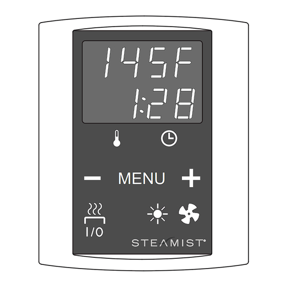
Contrtol Panel:
● Temperature adjustment range 104 - 194°F.
● Pre-setting time adjustment range 0 - 12 h.
● Lighting control, max. power 100W, 120V / 1PH
● Fan control, max. power 100W, 120V / 1PH
● Dimensions: 3.7" x 1.1" x 4.4"
Power Unit:
● Supply voltage
S170-1: 240V / 1PH
S170-3: 208V / 3PH
● Max. load
S170-1: 15kW / 240V / 1PH
S170-3: 14.4 kW / 208V / 3PH
● Dimensions: 11" x 3.1" x 7.9"
Sensor
● Temperature sensor NTC thermistor 22 kΩ / T= 77°F
● Resettable overheat protector
● Dimensions: 2" x 2.9" x 1.1"
● Weight 175g with leads, cable 13 ft.
- 1 -
Instructions for Installation and Use
ETL LISTED
CONFORMS TO
UL STD 875
CERTIFIED TO
CAN/CSA STD
E60335-2-53-05
Models: S170-1 and S170-3
MENU
®
Pub. No. 572-C
Advertisement
Table of Contents

Related Manuals for Steamist S170-1

Summary of Contents for Steamist S170-1
- Page 1 ● Max. load 1.1 General S170-1: 15kW / 240V / 1PH The Steamist Digital Sauna Control unit can be used to S170-3: 14.4 kW / 208V / 3PH control sauna heaters within an output range of 2.3 - 15 ● Dimensions: 11" x 3.1" x 7.9"...
- Page 2 Instructions for Installation and Use Figure 1 - System Components Control Panel Temperature Sensor Heater (Not Included) Power Unit Main Switch 1.3 Troubleshooting NOTE: The overheat protector can be reset by user. All other maintenance must be done by professional mainte- If an error occurs, the power to the heater will be cut off nance personnel.
- Page 3 Instructions for Installation and Use Figure 2 - Control Panel Advanced Settings Changing between Farenheit to Celsius Display Open the settings menu by simultaneously pressing the control panel buttons -, MENU, Indicator Lights and +. Press for 5 seconds. Temperature Menu &...
- Page 4 Instructions for Installation and Use 3. Instructions for Installation The electrical connections of the control unit may only be 3.2 Installing the Power Unit made by a licensed electrician and in accordance with the Install the power unit to a wall outside the sauna room, in current regulations.
- Page 5 ● For driving a fan (max. 100W) and lighting (max. 100W). Instructions for Installation The power unit of the S170-1 is controlled by the digital control. Fuses on the electronics card (if a fuse has blown, see section ● Control panel is connected to power unit via data cable.
- Page 6 Instructions for Installation and Use Table 3 - Wire and Fuse sizes (S170-3) Wire Size AWG 90°C Breaker to Power Unit Power Unit to Heater Model Watts Amps Voltage Phase 1@30A - #10 AWG copper 90°C #10 AWG copper 90°C SMS-80R-3 8,000 22.2...
- Page 7 Instructions for Installation and Use 3. Instructions for Installation 3.2.1 Electrical Connections 3.3 Installing the Temperature Sensor Floor-mounted heaters (see Figure 8) Figures 6 and 7 show the electrical connections of the power unit. Tables 2 and 3 show the wire and fuse sizes. For more ●...
- Page 8 007-1352 Steamist Limited Warranty Residential Applications period. In addition, Steamist will perform the required labor to repair Steamist will replace any defective components in their sauna or install the component, at the factory, for the period of one year from heaters, contactors, controls, used in residential applications, for the the original, purchase date.
Need help?
Do you have a question about the S170-1 and is the answer not in the manual?
Questions and answers