Table of Contents
Advertisement
Quick Links
Advertisement
Table of Contents

Summary of Contents for Hoverfly HoverflySPORT
- Page 1 HoverflySPORT™ User’s Guide...
- Page 2 Copyright © Hoverfly Technologies, Inc. 2011. All rights reserved. Except as permitted under the Copyright Act of 1976 US Code § 102 101-122, no part of this publication may be reproduced or distributed in any form or by any means, or stored in a database or retrieval system, without the prior written permission of Hoverfly Technologies, Inc.
- Page 3 HoverCore™ technology inside every HoverflySPORT™. We hope that you enjoy using the HoverflySPORT™ for many years. This product is the base for a line of add-ons to take your flying to the next level. Please understand that software is never finished. We will periodically release new versions of firmware which can easily be loaded onto the HoverflySPORT™...
- Page 4 HoverflySPORT™ HoverflySPORT™ User’s Guide Page 4 of 67...
- Page 5 All ways maintain control of your aircraft! One moment of showing-off can lead to a lifetime of regret. There are old pilots and bold pilots but there are few old bold pilots. HoverflySPORT™ User’s Guide Page 5 of 67...
-
Page 6: Table Of Contents
Table of Contents About!this!guide! ..........................................!10 Content!Division!............................................!10 When!to!use!the!guide!..........................................!11 Format! ..............................................!11 Revisions!...............................................!11 Introduction!to!the!HoverflySPORT™!....................................!12 Multi"Rotor!Aircraft!..........................................!12 Purpose!..............................................!13 Function!of!the!HoverflySPORT™!......................................!14 HoverCore™! ............................................!20 What’s!included!..........................................!21 In!the!box!..............................................!21 Also!included!............................................!22 Installation!and!Building! .........................................!23 HoverflySPORT™ User’s Guide Page 6 of 67... - Page 7 Current!vs.!Wire!Gauge!........................................!29 4.5.3 Battery!Source! ...........................................!30 4.5.4 Electronic!Speed!Controllers!(ESCs)!....................................!31 4.5.5 Connectors!............................................!35 4.5.6 Wiring!Harness!Layout!........................................!36 4.5.7 Power!Filtering!..........................................!38 Airframe!..............................................!38 4.6.1 Airframe!Vibration!Dampening!......................................!38 4.6.2 Stand"offs!............................................!39 Brushless!Motors!...........................................!39 Propellers! ...............................................!40 Canopy! ..............................................!41 4.10 Connecting!the!HoverflySPORT™! ......................................!41 4.10.1 HoverflySPORT!Orientation! ......................................!42 HoverflySPORT™ User’s Guide Page 7 of 67...
- Page 8 4.10.2 Receiver!Connection!to!HoverflySPORT!™! ..................................!43 4.10.3 Configurations!"!!“+”!and!“X”! ......................................!44 4.10.4 Configurations!–!Hex!and!Y6! ......................................!45 4.10.5 Configurations!–!Octo!and!X8! .......................................!46 Operation!............................................!47 Before!Flight! ............................................!47 Setting!Gains!............................................!48 Arming!the!HoverflySPORT™! .........................................!49 Bench!Testing! ............................................!52 Flight!Controls!............................................!53 Basic!Flight!Mode! ..........................................!54 Advanced!Flight!Mode!..........................................!54 5.7.1 Altitude!Hold!Function! ........................................!54 Update!Client!and!Setup!Utility!......................................!56 Firmware!Updates! ..........................................!57 6.1.1...
- Page 9 6.2.3 Diagnostics!Tab!..........................................!63 Appendix!A!–!Physical!Dimensions! ......................................!64 Appendix!B!"!Technical!Specifications!.....................................!65 Appendix!C!"!Quick!Start!Guide! .......................................!66 Appendix!D!"!Connection!Reference!.......................................!67 HoverflySPORT™ User’s Guide Page 9 of 67...
-
Page 10: About!This!Guide
1 About this guide Ideally this User’s Guide represents the complete documentation for the HoverflySPORT™. We will make corrections and revision changes as needed and certainly when new features are added. Quick Start Guide: If you already have a multi-rotor aircraft built and just want to Plug-N-Fly™... -
Page 11: When!To!Use!The!Guide
1.2 When to use the guide This guide is intended for builders and users of the HoverflySPORT™. It should be used when first installing the unit, before first flying your aircraft, and throughout the use of the product. The guide assumes that the user has some knowledge of power and servo connections, basic electronics, and updating the firmware of electronic devices. -
Page 12: Introduction!To!The!Hoverflysport
Therefore, the minimum number of motors that must be used with the HoverflySPORT™ is four (4). In addition, the orientation of these motors needs to be at equal angles. -
Page 13: Purpose
2.2 Purpose The HoverflySPORT™ in a very basic sense is the middle-man between your control inputs and the motor electronic speed controllers (ESCs). Without it the aircraft would be nearly if not completely impossible to fly. The original stealth fighter, the Lockheed F-117 Nighthawk, first flown in 1981 was a revolutionary aircraft for two reasons. -
Page 14: Function!Of!The!Hoverflysport
The purpose of the HoverflySPORT™ is to make the job of piloting an inherently unstable multi-rotor aircraft easy. Easy is a relative term here since some time on the sticks with other types of aircraft helps a great deal. However, we strive to make the HoverflySPORT™ the most capable Flight Controller on the market and this means over time easy will be even easier. - Page 15 ESCs is to take information from the HoverflySPORT™ and turn it into a 3-phase control signal. This 3-phase signal drives the brushless motor to attain a rotational speed to a certain number of revolutions per minute (RPM).
- Page 16 In order to move the quadcopter forward the pilot would actuate the elevator (European customers may use left stick on mode 1 transmitters, maybe find a different term) control input up on the transmitter. This will cause the HoverflySPORT™ to rotate the quadcopter forward called Pitch.
- Page 17 In other words, after you change altitude you will need to increase or decrease the throttle around the sweet spot to fix the altitude. This is especially true when decreasing altitude. Once the quadcopter moves down to the desired altitude a swift increase in throttle will be required to offset the momentum of the falling aircraft. HoverflySPORT™ User’s Guide Page 17 of 67...
- Page 18 Figure 4. Control stick movement and aircraft roll, pitch, yaw, and throttle (altitude). HoverflySPORT™ User’s Guide Page 18 of 67...
- Page 19 Flying a quadcopter with a HoverflySPORT™ is a bit different from other aircraft such as planes and helicopters. Take for example the case where the quadcopter is flying into a gust of wind. The HoverflySPORT™ will compensate for the wind so that the same user inputs achieve the same flight as in windless conditions.
-
Page 20: Hovercore
2.4 HoverCore™ The HoverflySPORT™ flight controller system is based on our core Sensor Data Fusion technology called HoverCore™. Lots of data from accelerometers and gyroscopes is useless no matter how fast you sample if the data is not fused effectively to provide stable flight control outputs. -
Page 21: What's!Included
3 What’s included 3.1 In the box The following items should all be included with your HoverflySPORT™ product: HoverflySPORT™ Vibration Grommets USB Cable HoverCore™ sticker (when in stock) Suggestion: When you are finished building your multi-rotor aircraft place the HoverCore™ sticker on the airframe or canopy and send us a picture to post on our website! Mailto: info@hoverflytech.com... -
Page 22: Also!Included
3.2 Also included In addition to the hardware you purchased the following is included with your purchase: HoverflySPORT™ User’s Guide (this manual) – Downloadable in PDF format from http://www.hoverflytech.com/Documentation.html E-Mail support – support@hoverflytech.com Forum Support – http://www.rcgroups.com/hoverfly-technologies-711/ Firmware Update Client - http://www.hoverflytech.com/Software_Updates.html... -
Page 23: Installation!And!Building
These grommets mechanically de-couple the HoverflySPORT™ from the airframe substantially. Over tightening the screws holding the HoverflySPORT™ to the standoffs will negate the beneficial aspects of the grommets. Hand tighten these screws lightly to hold the HoverflySPORT™ onto the airframe but do not compress the grommets too much. -
Page 24: Configurations
4.2 Configurations The HoverflySPORT™ can be configured using the Update Client (see Chapter 6) so that it may be used on several different types of multi- rotor aircraft. The basic configurations are X, +, Hex, Octo, Y6, and X8. All of these configurations are shown in Fig. 5 shown below. -
Page 25: Transmitter
Flight requires the use of 5 channels. The four main channels are associated with the two control sticks and are used for Roll, Pitch, Yaw, and Throttle. The fifth additional channel is used to control the Gain of the HoverflySPORT™ control. The Gain is the parameter that is used to tune the performance of your multi-rotor aircraft. - Page 26 End point adjustment 100% for “+” and “-“ sides Dual-Rates (D/R) 100% Channel Reverse Normal – HiTec, Spektrum, JR Reversed - Futaba Trims Centered Sub Trims Centered Exponential After experienced add up to 30% into aileron and elevator HoverflySPORT™ User’s Guide Page 26 of 67...
-
Page 27: Receiver
4.4 Receiver The HoverflySPORT™ automatically senses the signal from which ever brand of Receiver that you choose for your aircraft. The power for your receiver will come from the channel connections to the HoverflySPORT™. However, the number of channels available on the receiver must be at least 5. -
Page 28: Motor!Wiring!Harness
4.5.1 Proper Soldering (read even if you know how to solder) The basic motor wiring harness consists of a battery, ESCs, and motors. The ESCs are connected to the HoverflySPORT™ which is covered in the next section. The high levels of currents required by the motors through the ESCs from the battery require both correct wire diameter (gauge) and good solder joints. -
Page 29: Current!Vs.!Wire!Gauge
So if you can’t touch a wire or solder joint for more than approximately 5 seconds it is liable to fail at some point during operation. Increase the gauge of your wire or re-solder the joint. HoverflySPORT™ User’s Guide Page 29 of 67... -
Page 30: Battery!Source
All of these cell configurations can be used with the HoverflySPORT™ (See Chapter 8 for Maximum ratings). You should follow all manufacturers warnings concerning using and charging your batteries. A cell-balancer should always be used on high- capacity LiPo batteries. -
Page 31: Electronic!Speed!Controllers!(Escs)
It should also be noted that brushed motors generate a large amount of Electro-Magnetic Pulse noise because of the arcing between the brushes and the contacts on the rotor. Use of brushed motors has not been tested on the HoverflySPORT and it is recommended that the user NOT use them. - Page 32 As a general rule, you should always use an ESC with twice the maximum current that you believe will be utilized by the motors. You can match the maximum current to the ESC current rating HoverflySPORT™ User’s Guide Page 32 of 67...
- Page 33 The following is a suggested order for set-up and calibration that you should refer to while observing the guide that was supplied with your ESC. PWM Frequency: The HoverflySPORT uses PWM output frequencies higher than the standard 50Hz accepted by most ESCs. Therefore there are some brands that do NOT work: Jeti and Scorpion.
- Page 34 ALL of the ESCs in your system. Start by connecting a single ESC to the throttle channel of the receiver. Then connect the battery to the ESC and use the ESC manual to complete the calibration using your transmitter. The following steps are the typical calibration procedure for most ESCs. HoverflySPORT™ User’s Guide Page 34 of 67...
-
Page 35: Connectors
Remember that just like the wire gauge you choose the connectors must also be sized correctly. All connectors have an associated current capacity. You should follow the manufacturer’s specification when designing your wire harness. When soldering your connectors and HoverflySPORT™ User’s Guide Page 35 of 67... -
Page 36: Wiring!Harness!Layout
The wiring harness includes the wire connections from the battery through the ESCs to the motors. The following diagram is a suggested layout for your wiring harness. Use this diagram if you have no experience with building multi-rotor aircraft. Your layout should differ only if you have extensive experience with wiring. HoverflySPORT™ User’s Guide Page 36 of 67... - Page 37 ESC outputs HoverflySPORT Connect power from a single ESC to the HoverflySPORT to power the Receiver. Motor Motor Motor Motor Figure 9. Typical wiring harness layout. HoverflySPORT™ User’s Guide Page 37 of 67...
-
Page 38: Power!Filtering
(BEC). On board filtering eliminates the need to use any type of external power filtering. When connecting the ESCs to the HoverflySPORT the user should remove all but one of the power connections on the 3 pin hobby connector as shown in Fig. 9. -
Page 39: Stand"Offs
4.6.2 Stand-offs The HoverflySPORT™ should be mounted to the main platform using stand-offs. These are cylindrical aluminum, plastic, or rubber legs that are either threaded or hollow to accept a long mounting screw. The supplied vibration grommets should be used at all times between the HoverflySPORT™... -
Page 40: Propellers
APC to be durable and consistent. One in particular is the APC 12x3.8 SFP Slow Flyer Counter Rotating Propeller. If you are building a smaller aircraft then some of the GWS tri-blade propellers work well. Unfortunately, at this time there are few choices available on the market. HoverflySPORT™ User’s Guide Page 40 of 67... -
Page 41: Canopy
It is highly recommended that the sensitive and valuable flight control electronics of your aircraft be covered. The user will want to protect the HoverflySPORT with a hard shell cover or canopy. At some point, the aircraft will have a harder than expected landing. A simple cover will protect the electronics from broken propellers and other foreign object damage (FOD). -
Page 42: Hoverflysport!Orientation
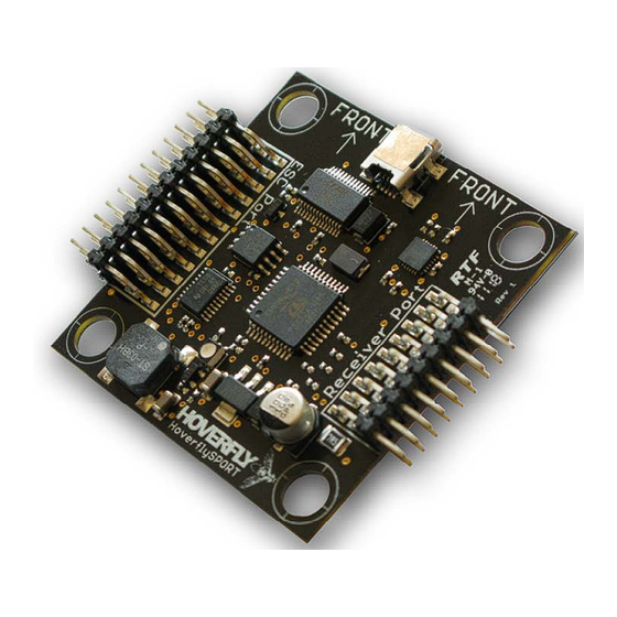
4.10.1 HoverflySPORT Orientation Two distinct arrows can be seen on the HoverflySPORT. These indicate the direction of forward movement for your aircraft. The picture below illustrates the correct orientation of the HoverflySPORT. Figure 10. Board orientation. HoverflySPORT™ User’s Guide Page 42 of 67... -
Page 43: Receiver!Connection!To!Hoverflysport
4.10.2 Receiver Connection to HoverflySPORT ™ Figure 11. Receiver to HoverflySPORT connections. HoverflySPORT™ User’s Guide Page 43 of 67... -
Page 44: Configurations!"!!"+"!And!"X
4.10.3 Configurations - “+” and “X” FRONT HoverflySPORT™ User’s Guide Page 44 of 67... -
Page 45: Configurations!–!Hex!And!Y6
4.10.4 Configurations – Hex and Y6 FRONT HoverflySPORT™ User’s Guide Page 45 of 67... -
Page 46: Configurations!–!Octo!And!X8
4.10.5 Configurations – Octo and X8 FRONT HoverflySPORT™ User’s Guide Page 46 of 67... -
Page 47: Operation
! None of the propellers are damaged. ! Each of the ESC are programmed and calibrated correctly (see previous chapter for settings). ! All HoverflySPORT™ connections to the ESCs and Receiver have been made correctly. ! The latest HoverflySPORT™ firmware is loaded (see Chapter 6). -
Page 48: Setting!Gains
The EPA travel value is used by the HoverflySPORT as the Primary Gain value for the aircraft. Moving the switch to the “UP” position or “ON” will allow the left side value to be adjusted. Use a negative value on the left side so that the HoverflySPORT will read the value correctly. -
Page 49: Arming!The!Hoverflysport
5.3 Arming the HoverflySPORT™ In order to use the HoverflySPORT™ and your aircraft you will have to connect the battery and arm the system. This should be done in the Bench Testing procedure after the aircraft is mounted to a test bench. The procedure will be described here so that you are familiar with it before starting your bench tests. - Page 50 5. To Arm the HoverflySPORT™ and aircraft, move the throttle stick to the left-bottom until you hear one beep. 6. Move the throttle stick to the right-bottom you should hear two beeps. The HoverflySPORT’s LED will blink RED During this period the HoverflySPORT is calibrating it’s internal sensors and should remain motionless.
- Page 51 Disconnect and re-connect power and repeat Arming procedure. Powered Trouble Mode Gyro Calibration Failure The HoverflySPORT performs a Gyro Calibration after power-up. If this calibration fails the LED will respond with a particular blinking sequence that is shown below. Powered Gyro Calibration Failure HoverflySPORT™...
-
Page 52: Bench!Testing
The first thing that you will want to verify is that the rotation of all of the propellers is correct. Start by connecting the battery source and Arming the HoverflySPORT™. Refer to the diagrams corresponding to your configuration (i.e., X, Hex, Y6, etc). Start by increasing the throttle stick slightly just until the propellers begin to spin. -
Page 53: Flight!Controls
The basic flight controls for Roll, Pitch, Yaw, and Throttle have been shown previously in this guide but the control diagram is repeated here. Figure 13. Control stick movement and aircraft roll, pitch, yaw, and throttle (altitude). HoverflySPORT™ User’s Guide Page 53 of 67... -
Page 54: Basic!Flight!Mode
Receiver Port (see 4.10.2). The user will need to solder a standard 3-pin servo connector onto the ultrasonic sensor as shown below. Figure 14. LV-MaxSonar-EZ0 and Connection Diagram http://www.maxbotix.com/MB1000__LV-MaxSonar-EZ0.html HoverflySPORT™ User’s Guide Page 54 of 67... - Page 55 While Altitude Hold is enabled the throttle channel no longer adjusts the throttle level directly. Instead the throttle stick controls the altitude based on the ultrasonic sensor. The user can change the altitude simply my increasing or decreasing the throttle. HoverflySPORT™ User’s Guide Page 55 of 67...
-
Page 56: Update!Client!And!Setup!Utility
6 Update Client and Setup Utility The Hoverfly Technologies Update Client is used to load the most current firmware onto the HoverflySPORT™ and future add-on boards. The Update Client requires a PC running Windows XP/Vista/7 (Mac OS not currently available). Download the latest version of the Update Client from http://www.hoverflytech.com/Software_Updates.html... -
Page 57: Firmware!Updates
6.1 Firmware Updates To use the software, simply connect the HoverflySPORT™ via the supplied USB cable to the computer. Follow the instructions for programming included in the Update Client software. 6.1.1 Update Procedure Download and run the Update Client Agree to License Agreement HoverflySPORT™... - Page 58 Select the HoverflySPORT Select Aircraft Configuration HoverflySPORT™ User’s Guide Page 58 of 67...
- Page 59 Wait for board to Connect. Use Download Driver only if board will not connect. HoverflySPORT™ User’s Guide Page 59 of 67...
- Page 60 Select desired Software Version and press the “Flash” button. HoverflySPORT™ User’s Guide Page 60 of 67...
-
Page 61: Setup!Utility
6.2.1 General Tab Once the HoverflySPORT Setup Utility is installed and the board is connected via USB you will see real-time feedback on the operation of the HoverflySPORT. Understand that the buttons and sliders are not user adjustable, they are only a visual display of current values. When the board or aircraft (if it is already installed) is moved (Roll, Pitch, and Yaw) the Gyro and Accelerometer values will change. - Page 62 Screen shot of Setup Utility HoverflySPORT™ User’s Guide Page 62 of 67...
-
Page 63: Parameters!Tab
6.2.3 Diagnostics Tab The Diagnostics Tab will allow you to test your HoverflySPORT for proper operation. Pressing the Test button will provide the user with instructions on how to test the flight controller. Results of the tests will be displayed by the check boxes. -
Page 64: Appendix!A!–!Physical!Dimensions
Appendix A – Physical Dimensions HoverflySPORT™ User’s Guide Page 64 of 67... -
Page 65: Appendix!B!"!Technical!Specifications
Receiver Input Signal PWM (all receivers) Current consumption <100mA PC Connection Update Client Operating System Windows XP/Vista/7 Mounting Standoffs with vibration grommets Water resistance None ESD requirement User should use appropriate ESD protection HoverflySPORT™ User’s Guide Page 65 of 67... -
Page 66: Appendix!C!"!Quick!Start!Guide
Appendix C - Quick Start Guide HoverflySPORT™ User’s Guide Page 66 of 67... -
Page 67: Appendix!D!"!Connection!Reference
Appendix D - Connection Reference HoverflySPORT™ User’s Guide Page 67 of 67...
Need help?
Do you have a question about the HoverflySPORT and is the answer not in the manual?
Questions and answers