
Related Manuals for Ceta 104

Summary of Contents for Ceta 104
- Page 1 BA_CETA104_EbV_EN_0450021002_0933-10.book Seite 1 Dienstag, 8. September 2009 10:20 10 Operating manual Heating circuit controller with burner control and DHW charging control Version 0933-10 Art. 0450021002...
-
Page 2: Table Of Contents
BA_CETA104_EbV_EN_0450021002_0933-10.book Seite 2 Dienstag, 8. September 2009 10:20 10 Contents Scope of delivery .......................1 General ..........................1 Intended use ........................1 Safety ..........................1 General key functions ...................... 2 Version display (when starting) ..................2 Basic display ........................3 Functions with direct access ..................4 Menu level .........................5 Parameter description .....................8 Installation ........................ -
Page 3: Scope Of Delivery
BA_CETA104_EbV_EN_0450021002_0933-10.book Seite 1 Dienstag, 8. September 2009 10:20 10 Scope of delivery 1. 1x Central unit CETA 104 5. 8x Screw, plate 2.9x19 mm 2. 1x Outside sensor AF200 6. 3x Screw assembly 4x35 mm 3. 1x Boiler immersion sensor 7. -
Page 4: General Key Functions
•Change menu item •Exit setting •Keep old value •Select next higher menu level Esc-Lang •Return to basic display 2. Version display (when starting) c 104= Type designation Ceta 104 1.5= Version display (due to update it can differ from example shown) -
Page 5: Basic Display
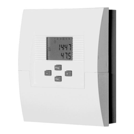
BA_CETA104_EbV_EN_0450021002_0933-10.book Seite 3 Dienstag, 8. September 2009 10:20 10 Basic display 3. Basic display Display weekday 14:48 Display time 47.5°C Temperature F1 heat generator Explanation of symbols Display heat generator in operation Display pump function heating circuit Display pump function tank loading Automatic mode heating circuit after timer program I or II Heating mode heating circuit (Operating mode AUTOMATIC or HEATING) -
Page 6: Functions With Direct Access
BA_CETA104_EbV_EN_0450021002_0933-10.book Seite 4 Dienstag, 8. September 2009 10:20 10 Functions with direct access 4. Functions with direct access Manual operation Controller is in manual mode — Activate by pressing and holding button — Change heat generator setpoint via buttons — end function by pressing button Function: Manual operation allows manual start-up of the system, e.g. -
Page 7: Menu Level
BA_CETA104_EbV_EN_0450021002_0933-10.book Seite 5 Dienstag, 8. September 2009 10:20 10 Menu level 5. Menu level Basic display General menu structure Prog Select parameters Menu 01 Prog 02:01 02:02 02:nn Menu 02 Parameter 01 Parameter 02 Last parameter Prog Prog Value 1 Calibration Set parameter value Return... - Page 8 BA_CETA104_EbV_EN_0450021002_0933-10.book Seite 6 Dienstag, 8. September 2009 10:20 10 Menu level Overview of menu level Basic display Prog 04:01 03:01 03:02 03:03 03:04 Temperature Info Outdoor actual Outdoor long-term Outdoor min Outdoor max heat generator Prog 05:03 05:05 06:01 05:04 06:04 Actual value Display...
- Page 9 (time) (temperature) differential temperature limit X2: Function only in bus connection X3: Are hidden when activating code 03:09 X4: Only when connecting CETA RC X5: Only in conjunction with heat generator connection via OpenTherm, and when supported by heat generator...
-
Page 10: Parameter Description
BA_CETA104_EbV_EN_0450021002_0933-10.book Seite 8 Dienstag, 8. September 2009 10:20 10 Parameter description 6. Parameter description 01 Information level Display Designation Description 03:01 Outdoor actual Current outside temperature 03:02 Outdoor long-term Average long-term value of outside temperature. Depending on set building type (03:04), the value is averaged longer or shorter. 03:03 Outdoor min Minimum outside temperature value (0.00 to 24.00 h) - Page 11 BA_CETA104_EbV_EN_0450021002_0933-10.book Seite 9 Dienstag, 8. September 2009 10:20 10 Parameter description Display Designation Description 07:02 DHW actual value Sensor mode: Actual temperature on DHW sensor Thermostat mode: 0 = Input open 1 = Input closed 07:03 DHW setpoint Setpoint temperature for DHW tank 02 Time programs Cycle of Switch-on...
- Page 12 BA_CETA104_EbV_EN_0450021002_0933-10.book Seite 10 Dienstag, 8. September 2009 10:20 10 Parameter description 03 Parameter system Display Designation Description 03:01 Code entry Setting range: 0 … 999 Factory setting: 0 Function: Show parameters marked with X3. 03:02 Automatic set 0=OFF, no automatic sensor detection function 1=ON, automatic sensor detection 03:04...
- Page 13 Control of a single-stage heat generator via a relay output Control of a heat generator with standardised OpenTherm interface via setpoint transfer Note: only possible if OpenTherm logo is available on CETA 104 04:02 Minimum Setting range: 5 °C … 95 °C temperature limit H- Factory setting: 38 °C...
- Page 14 BA_CETA104_EbV_EN_0450021002_0933-10.book Seite 12 Dienstag, 8. September 2009 10:20 10 Parameter description Display Designation Description 04:05 Minimum burner Setting range: 0…20 Min run time Factory setting: 2 min Function: After starting the heat generator, at least the set time must lapse before the heat generator is deactivated again. Note: The maximum temperature limit takes priority over this function.
- Page 15 BA_CETA104_EbV_EN_0450021002_0933-10.book Seite 13 Dienstag, 8. September 2009 10:20 10 Parameter description Display Designation Description 06:04 Operating mode Setting range: 1: Automatic 2: Heating 3: Red. heating 4: Standby Factory setting: 1 Function: Automatic: Heating circuit operates in Heating or Red. heating mode according to the time program assigned under 06:05 Heating: Heating circuit operates continuously...
- Page 16 BA_CETA104_EbV_EN_0450021002_0933-10.book Seite 14 Dienstag, 8. September 2009 10:20 10 Parameter description Display Designation Description 06:07 Heating curve/ Setting range: 0.05 … 3.50 conductance Factory setting: 1.50 Function: Determines the heating curve for the heating circuit. 06:08 Heating system Setting range: 1.00…10.00 (exponent) Factory setting:...
- Page 17 BA_CETA104_EbV_EN_0450021002_0933-10.book Seite 15 Dienstag, 8. September 2009 10:20 10 Parameter description Display Designation Description 06:10 Summer switch-off Setting range: OFF (----) 10 °C ... 30 °C Factory setting: 20 °C Function: Switch-off of heating operation at outside temperatures above the desired outside temperature. 06:11 Extended pump Setting range:...
- Page 18 BA_CETA104_EbV_EN_0450021002_0933-10.book Seite 16 Dienstag, 8. September 2009 10:20 10 Parameter description 07 DHW parameters Display Designation Description 07:01 Function Setting range: 0 = OFF 1 = Sensor mode 2 = Thermostat mode 3 = Automatic mode DHW Factory setting: Function: Sensor mode: Control via temperature sensor in domestic hot water tank...
- Page 19 BA_CETA104_EbV_EN_0450021002_0933-10.book Seite 17 Dienstag, 8. September 2009 10:20 10 Parameter description Display Designation Description 07:04 Operating mode Setting range: 1: Automatic 2: Heating 3: Red. heating 4: Standby Factory setting: 1 Function: Automatic: DHW operates in Heating or Red. heating mode according to the time program assigned under 07:05 Heating: DHW operates continuously according to set...
- Page 20 BA_CETA104_EbV_EN_0450021002_0933-10.book Seite 18 Dienstag, 8. September 2009 10:20 10 Parameter description Display Designation Description 07:07 Legionella Setting range: 00:00 … 23:00 o'clock protection (time) Factory setting: 02:00 o'clock Function: This value is used to set the time at which the legionella protection function is to be started on the set weekday (see 07:06).
- Page 21 BA_CETA104_EbV_EN_0450021002_0933-10.book Seite 19 Dienstag, 8. September 2009 10:20 10 Parameter description Display Designation Description 07:12 Extended pump Setting range: 0…60 Min running time Factory setting: 5 min Function: After switching off the heat generator, the tank loading pump is stopped after a time delay to prevent a safety switch-off in case of high temperatures.
- Page 22 BA_CETA104_EbV_EN_0450021002_0933-10.book Seite 20 Dienstag, 8. September 2009 10:20 10 Parameter description 26 Time setting Display Designation Description 26:01 Time Setting range: 00:00 ... 23:59 Factory setting: Current time Function: Setting of current time. 26:02 Weekday Setting range: 1 ... 7 Factory setting: Current weekday Function: Setting of current weekday.
-
Page 23: Installation
BA_CETA104_EbV_EN_0450021002_0933-10.book Seite 21 Dienstag, 8. September 2009 10:20 10 Mounting Mounting Hazard! Mounting must be performed by an authorised professional electrician! Ensure that unit is de-energised before opening it! Drilling pattern for wall fastening 1. Remove terminal area cover from casing. -
Page 24: Connection Diagram
BA_CETA104_EbV_EN_0450021002_0933-10.book Seite 22 Dienstag, 8. September 2009 10:20 10 Connection diagram 8. Connection diagram Hazard! Connection must be performed by an authorised professional electrician! Ensure that unit is de-energised before opening it! 230V connections Low voltage connections... -
Page 25: Fault Clearance
Data bus OpenTherm Repair malfunction on data bus to no signal (terminal OT) heat generator 72-6 Data bus CETA RC no signal (terminal Repair malfunction on data bus to room unit CETA RC 73-2 Unit bus address collision (Terminal Set controls of the same type to... -
Page 26: Sensor Resistance Values
BA_CETA104_EbV_EN_0450021002_0933-10.book Seite 24 Dienstag, 8. September 2009 10:20 10 Sensor resistance values 10. Sensor resistance values Depending on temperature: PT1000 KVT20/2/6, AF200 T (°C) R (kOhm) T (°C) R (kOhm) 1.155 1.783 1.194 1.812 1.232 1.840 1.271 1.869 1.309 1.898 1.347 1.928 1.385... -
Page 27: Declaration Of Conformity
BA_CETA104_EbV_EN_0450021002_0933-10.book Seite 25 Dienstag, 8. September 2009 10:20 10 Declaration of conformity 11. Declaration of conformity... -
Page 28: Technical Data
BA_CETA104_EbV_EN_0450021002_0933-10.book Seite 26 Dienstag, 8. September 2009 10:20 10 Technical Data 12. Technical Data Mains voltage: 230V +6%/ -10% Rated frequency: 50...60Hz Power input: max. 2.1VA Fuse: 6.3A Output relay contact load: 2 (2)A Ambient temperature: -10...+50 °C Storage temperature: -25...+80 °C Degree of protection: IP 30...
Need help?
Do you have a question about the 104 and is the answer not in the manual?
Questions and answers