Mitsubishi SUZ-KA09NA Service Manual

Mitsubishi SUZ-KA09NA Service Manual

Split-type, heat pump air conditioners

Advertisement

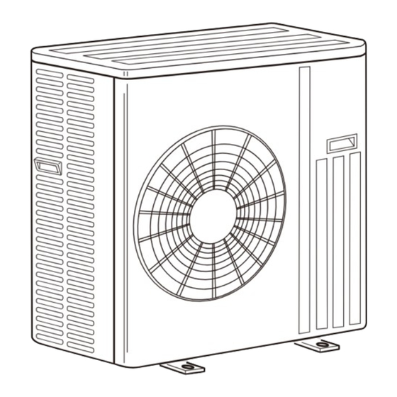
SPLIT-TYPE, HEAT PUMP AIR CONDITIONERS

SERVICE MANUAL

R410A

Outdoor unit

[Model Names]
SUZ-KA09NA
SUZ-KA12NA
SUZ-KA15NA
SUZ-KA18NA
SUZ-KA18NA.TH
[Service Ref.]
SUZ-KA09NA.TH
SUZ-KA12NA.TH
SUZ-KA15NA.TH
SUZ-KA18NA.TH
Revision:
• Modified some contents in
10.TROUBLESHOOTING in
REVISED EDITION-C.
• Some other descriptions have
been also modified.
• Please void OCH467
REVISED EDITIN-B.
Note:
This service manual describes
service data of the outdoor units
only.
• RoHS compliant products have
<G> mark on the spec name plate.
CONTENTS
2. PARTS NAMES AND FUNCTIONS .................... 2
3. SPECIFICATION ................................................. 3
4. OUTLINES AND DIMENSIONS .......................... 4
5. WIRING DIAGRAM ............................................ 5
7. DATA ................................................................. 11
8. ACTUATOR CONTROL .................................... 13
9. SERVICE FUNCTION ....................................... 14
10. TROUBLESHOOTING ...................................... 14
11. FUNCTION SETTING ....................................... 32
12. DISASSEMBLY INSTRUCTIONS ..................... 35
PARTS CATALOG (OCB467)
May 2014
No.OCH467
REVISED EDITION-C
HFC
utilized
R410A

Advertisement

Table of Contents
loading

Summary of Contents for Mitsubishi SUZ-KA09NA

  • Page 1: Table Of Contents

    R410A SERVICE MANUAL R410A Outdoor unit Revision: [Model Names] [Service Ref.] • Modified some contents in 10.TROUBLESHOOTING in SUZ-KA09NA.TH REVISED EDITION-C. SUZ-KA09NA • Some other descriptions have SUZ-KA12NA.TH been also modified. SUZ-KA12NA • Please void OCH467 SUZ-KA15NA.TH REVISED EDITIN-B.
  • Page 2: Combination Of Indoor And Outdoor Units

    — — OCH487 SLZ-KA12NA.TH — — — OCB487 SLZ-KA15NA.TH — — — PARTS NAMES AND FUNCTIONS SUZ-KA09NA SUZ-KA12NA SUZ-KA15NA OUTDOOR UNIT Air inlet (back and side) Piping Drain hose Air outlet Drain outlet SUZ-KA18NA OUTDOOR UNIT Air inlet (back and side)
  • Page 3: Specification

    SPECIFICATION Outdoor unit model SUZ-KA09NA SUZ-KA12NA SUZ-KA15NA SUZ-KA18NA Power supply V , phase , Hz 208/230 , 1 , 60 Max. fuse size (time delay) Min. circuit ampacity Fan motor F.L.A 0.50 0.93 Model KNB073FQDHC KNB092FQAHC SNB130FQBH R.L.A 10.0 Compressor L.R.A...
  • Page 4: Outlines And Dimensions

    OUTLINES AND DIMENSIONS SUZ-KA09NA SUZ-KA12NA SUZ-KA15NA Unit: inch REQUIRED SPACE Basically open 4 inches or more without any obstruction in front 15-3/4 Drain hole 1-5/8 and on both sides of the unit. Air in Air in 1-9/16 Air out 2- 3/8...
  • Page 5: Wiring Diagram

    WIRING DIAGRAM SUZ-KA09NA SUZ-KA12NA OCH467C...
  • Page 6 SUZ-KA15NA OCH467C...
  • Page 7 SUZ-KA18NA OCH467C...
  • Page 8: Refrigerant System Diagram

    REFRIGERANT SYSTEM DIAGRAM SUZ-KA09NA Unit: inch (mm) Refrigerant pipe ø3/8 4-way valve (with heat insulator) Muffler Outdoor heat exchanger Stop valve temperature (with service port) thermistor Outdoor Muffler Discharge RT68 heat Flared connection temperature exchanger thermistor Service port RT62 Ambient...
  • Page 9 SUZ-KA18NA Unit: inch (mm) Muffler Refrigerant pipe ø #100 4-way valve (with heat insulator) Stop valve Service port (with service port) Outdoor Flared connection Discharge heat Ambient Defrost temperature exchanger temperature thermistor thermistor thermistor RT61 RT62 RT65 Service port Compressor Outdoor heat exchanger temperature...
  • Page 10 ADDITIONAL REFRIGERANT CHARGE (R410A: oz.) Refrigerant piping exceeding 25 ft. requires additional refrigerant charge according to the calculation. Refrigerant piping length (one way): ft. Outdoor unit Model precharged SUZ-KA09NA 1 lb. 16 oz. SUZ-KA12NA 1.62 4.86 8.10 11.34 12.96 2 lb. 9 oz.
  • Page 11: Data

    0.07 0.05 0.09 0.07 0.09 0.07 Current 0.51 0.39 0.57 0.46 0.74 0.63 0.74 0.63 Outdoor unit SUZ-KA09NA SUZ-KA12NA SUZ-KA15NA SUZ-KA18NA Power supply (V, phase, Hz) 230, 1, 60 Input 0.61 0.98 0.85 1.09 1.08 1.43 1.39 1.63 Current 2.80 4.33...
  • Page 12 230, 1, 60 Input 0.08 0.08 0.09 0.09 0.09 0.09 Current 0.35 0.35 0.40 0.40 0.65 0.65 Outdoor unit SUZ-KA09NA SUZ-KA12NA SUZ-KA15NA Power supply (V, phase, Hz) 230, 1, 60 Input 0.63 0.86 0.84 1.10 1.38 1.87 Current 3.12 4.02 3.82 4.93...
  • Page 13: Actuator Control

    ACTUATOR CONTROL SUZ-KA09NA SUZ-KA12NA SUZ-KA15NA SUZ-KA18NA 8-1. OUTDOOR FAN MOTOR CONTROL The fan motor turns ON/OFF, interlocking with the compressor. [ON] The fan motor turns ON 5 seconds before the compressor starts up. [OFF] The fan motor turns OFF 15 seconds after the compressor has stopped running.
  • Page 14: Service Function

    SERVICE FUNCTIONS SUZ-KA09NA SUZ-KA12NA SUZ-KA15NA SUZ-KA18NA 9-1. CHANGE IN DEFROST SETTING Changing defrost finish temperature <JS> To change the defrost finish temperature, cut/solder the JS wire of the outdoor inverter P.C. board. (Refer to "10-6. TEST POINT DIAGRAM AND VOLTAGE".)
  • Page 15 10-2. TROUBLE SHOOTING CHECK TABLE SUZ-KA09NA SUZ-KA12NA SUZ-KA15NA SUZ-KA18NA check Symptoms Condition Remedy Abnormal point/ Condition indication code Overcurrent protection cut-out operates 3 consecutive times Outdoor unit 1-time flash Outdoor power sys- • Reconnect connector of compressor. • Refer to “10-5. How to check in- does not op- within 1 minute after the compressor gets started.
  • Page 16: How To Proceed "Self-Diagnosis

    10-3. HOW TO PROCEED "SELF-DIAGNOSIS" As this air conditioner has a function to memorize all the failures that had occurred, the latest failure detail can be recalled by following the procedure below. Use this function when the check code is not displayed with wired remote controller or the re- mote controller at use is wireless type.
  • Page 17 Reset the error history. Display the error history in the diagnosis result display screen (see step When the error history is reset, the display will look like the one shown below. Press the ON/OFF button ( in the picture in the previous page) twice However, if you fail to reset the error history, the error content will be displayed again.
  • Page 18 10-3-4. Self-diagnosis <Wireless remote controller> <In case of trouble during operation> When a malfunction occurs to air conditioner, both indoor unit and outdoor unit will stop and operation lamp blinks to inform unusual stop. < Malfunction-diagnosis method at maintenance service> [Procedure] 1.
  • Page 19 • Refer to the following tables for details on the check codes. [Output pattern A] Beeper sounds Beep Beep Beep Beep Beep Beep Beep OPERATION · · · Repeated INDICATOR lamp flash pattern Approx. 2.5 sec. 0.5 sec. 0.5 sec. 0.5 sec.
  • Page 20: Trouble Criterion Of Main Parts

    10-4. TROUBLE CRITERION OF MAIN PARTS SUZ-KA09NA SUZ-KA12NA SUZ-KA15NA SUZ-KA18NA Part name Check method and criterion Figure Defrost thermistor (RT61) Measure the resistance with a tester. Fin temperature Refer to “Inverter P.C. board” in "10-6. TEST POINT DIAGRAM AND thermistor (RT64) VOLTAGE”, for the chart of thermistor.
  • Page 21: Troubleshooting Flow

    10-5. TROUBLESHOOTING FLOW A How to check inverter/compressor Disconnect the connector (CN61) between compressor and the intelligent power module (IPM). Check the voltage between terminals. See 10-5. “Check of open phase”. Are the voltages balanced? Replace the inverter P.C. board. Check the compressor.
  • Page 22 D Check of compressor winding ● Disconnect the connector (CN61) between the compressor and intelligent power module, and measure the resistance be- tween the compressor terminals. <<Measurement point>> at 3 points BLK - WHT Measure the resistance between the lead wires at 3 points. BLK - RED WHT - RED <<Judgement>>...
  • Page 23 G Check of outdoor thermistors Disconnect the connector of thermistor in the outdoor P.C. board (see below table), and measure the resistance of thermistor. Is the resistance of thermistor normal? Replace the thermistor except RT64. When RT64 is (Refer to "10-6.TEST POINT DIAGRAM AND VOLTAGE".) abnormal, replace the inverter P.C.
  • Page 24 I Check of outdoor fan motor SUZ-KA09/12/15NA Disconnect CN932 from the inverter P.C. board, and measure the resistance of the outdoor fan motor. Is the resistance of outdoor fan motor normal? Replace the outdoor fan motor. (Refer to "10-4. TROUBLE CRITERION OF MAIN PARTS".) Replace the inverter P.C.
  • Page 25 J Check of power supply Disconnect the connector (CN61) between compressor and intelligent power module. Rectify indoor/outdoor Turn ON power supply and press connecting wire. the TEST button twice. Replace the indoor Is there voltage 208/230 VAC Does the POWER lamp on remote between the indoor terminal electronic control P.C.
  • Page 26 K Check of LEV (Expansion valve) Self-check start. (Refer to “10-2.TROUBLESHOOTING CHECK TABLE”.) Expansion valve operates in full-opening direction. Note: Do you hear the expansion valve "click, Regardless of normal or abnormal condition, a short beep is emitted once the signal is received. click·······"? Do you feel the expansion valve vibrate on touching it ?
  • Page 27 L Check of inverter P.C. board Check the outdoor fan motor. (Refer to "10-5. . Check of outdoor fan motor".) Is the fuse (F901) blown on the inverter P.C. board? Check the connection of the connectors (CN931, CN932) of the outdoor fan motor. If the connection is poor, make it correct.
  • Page 28 M How to check miswiring and serial signal error Turn OFF the power supply. Is there rated voltage in the power supply? Check the power supply. Turn ON the power supply. Is there rated voltage between outdoor terminal block S1 and S2? Check the wiring.
  • Page 29 N Electromagnetic noise enters into TV sets or radios Is the unit grounded? Ground the unit. Is the distance between the antennas Extend the distance between the antennas and and the indoor unit within 9.91 ft., or is the indoor unit, and/or the antennas and the the distance between the antennas and outdoor unit.
  • Page 30 10-6. TEST POINT DIAGRAM AND VOLTAGE Inverter P.C. board SUZ-KA09NA SUZ-KA12NA SUZ-KA15NA Smoothing Smoothing Smoothing Bus-bar voltage capacitor capacitor capacitor DB61 Fuse (F701) Back side of unit (C63) (C62) (C61) DC 260-325 V T3.15 AL 250 V Fuse (F801) AC 208/230 V R.V.coil (CN721)
  • Page 31 SUZ-KA18NA Smoothing Smoothing Smoothing Bus-bar voltage capacitor capacitor capacitor Fuse (F701) DB61 Back side of unit (C62) (C61) (C63) T3.15 AL 250 V DC 260-325 V R.V.coil Fuse (F801) (CN721) AC 208/230 V 250 V 3.15 A 208/230 VAC Fuse (F901) T3.15 AL 250 V Output to drive...
  • Page 32: Function Setting

    FUNCTION SETTING 11-1. UNIT FUNCTION SETTING BY THE REMOTE CONTROLLER (S series only) Each function can be set according to necessity using the remote controller. The setting of function for each unit can only be done by the remote controller. Select function available from the table 1. <Table 1>...
  • Page 33 11-1-1. Selecting functions using the wired remote controller First, try to familiarize yourself with the flow of the function selection procedure. In this section, an example of setting the room temperature detection position is given. For actual operations, refer to steps 1 to 0 . Setting number Refrigerant address Unit number...
  • Page 34 [Operating Procedure] Check the function selection settings. Changing the function selection settings for each mode will change its relevant mode function. Perform steps 2 through 7 to check all the function selection settings, and write down the current settings in the Check column of the function selection <Table 1> in the chapter 11-1, and then change the settings as necessary. For the initial settings, refer to the <Table 1>...
  • Page 35: Disassembly Instructions

    Hold the sleeve, and Pull the terminal while pull out the terminal pushing the locking slowly. Locking lever lever. Connector SUZ-KA09NA SUZ-KA12NA SUZ-KA15NA NOTE: Turn OFF power supply before disassembling. OPERATING PROCEDURE PHOTOS 1. Removing the cabinet Photo 1 (1) Remove the screw fixing the service panel.
  • Page 36 OPERATING PROCEDURE PHOTOS 2. Removing the inverter assembly, inverter P.C. board Photo 3 (1) Remove the cabinet and panels. (Refer to procedure 1.) Screws of the (2) Disconnect the lead wire to the reactor and the following relay panel connectors: <Inverter P.C.
  • Page 37 OPERATING PROCEDURE PHOTOS Photo 6 5. Removing outdoor fan motor (1) Remove the cabinet and panels. (Refer to procedure 1.) (2) Disconnect the following connectors: <Inverter P.C. board> CN931, CN932 (Fan motor) (3) Remove the propeller nut. (See Photo 7) (4) Remove the propeller.
  • Page 38 SUZ-KA18NA NOTE: Turn OFF power supply before disassembling. OPERATING PROCEDURE PHOTOS 1. Removing the cabinet Photo 1 (1) Remove the screws of the service panel. Screw of the top panel Screws of the cabinet (2) Remove the screws of the top panel. (3) Remove the screw of the valve cover.
  • Page 39 OPERATING PROCEDURE PHOTOS 2. Removing the inverter assembly, inverter P.C. board Photo 3 Screws of the relay panel (1) Remove the cabinet and panels. (Refer to procedure 1.) (2) Disconnect the lead wire to the reactor and the following con- nectors: <Inverter P.C.
  • Page 40 OPERATING PROCEDURE PHOTOS 4. Removing the discharge temperature thermistor, Photo 6 defrost thermistor, outdoor heat exchanger tempera- Outdoor heat Ambient temperature ture thermistor and ambient temperature thermistor exchanger temperature thermistor thermistor (1) Remove the cabinet and panels. (Refer to procedure 1.) (2) Disconnect the lead wire to the reactor and the following connectors: <Inverter P.C.
  • Page 41 OCH467C...
  • Page 42 HEAD OFFICE : TOKYO BLDG., 2-7-3, MARUNOUCHI, CHIYODA-KU, TOKYO 100-8310, JAPAN CCopyright 2010 MITSUBISHI ELECTRIC CORPORATION Distributed in May 2014 No.OCH467 REVISED EDITION-C Distributed in Aug. 2011 No.OCH467 REVISED EDITION-B New publication, effective May 2014 Distributed in Jul. 2011 No.OCH467 REVISED EDITION-A Specifications are subject to change without notice.

This manual is also suitable for:

Suz-ka12naSuz-ka15naSuz-ka18na

Table of Contents