
Related Manuals for Microwave Radio Communications MRX4000 PLUS


Summary of Contents for Microwave Radio Communications MRX4000 PLUS
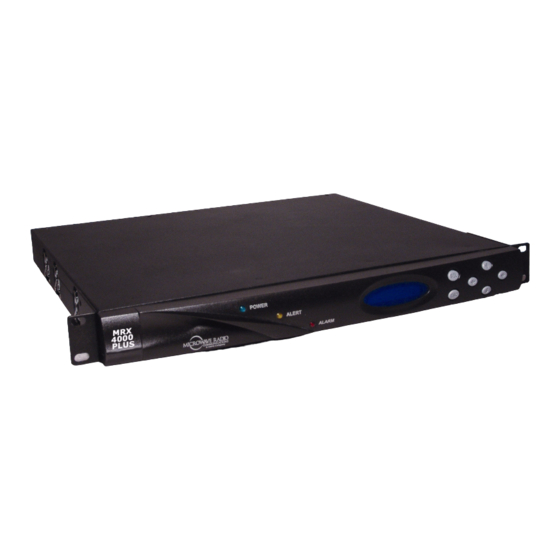
- Page 1 MRX4000 PLUS High Performance Analog + Digital Integrated Receiver Decoder (IRD) Manual Part No. 400537-1 Operator’s Guide Rev. B May 2008...
-
Page 3: Notices
No Microwave Radio Communications has made every effort to part of this material, nor any copies hereof, shall in any manner ensure the accuracy of the material contained in this manual at be disclosed, disseminated, or made available by purchaser or the time of printing. -
Page 4: Conventions
Except for this notification and the proper marking of products case of a fault, or the terminal on a protective earth with the appropriate symbol, Microwave Radio Communications electrode. MRX4000 PLUS Operator’s Guide... -
Page 5: On-Line Viewing
MRC. It is Buyer's responsibility to return, at its expense, the behalf except as set forth herein. If any payment is due MRC for allegedly defective product to MRC. Buyer must obtain a Return MRX4000 PLUS Operator’s Guide Notices... -
Page 6: Products Manufactured By Others
No warranties may be implied from any course of dealing or usage of trade. Buyer agrees that the exclusion of all warranties, other than those expressly provided herein, is reasonable. MRX4000 PLUS Operator’s Guide Notices... -
Page 7: Table Of Contents
System Operation - - - - - - - - - - - - - - - - - - - - - - - - - 2-5 MRX4000 PLUS Configurations- - - - - - - - - - - - - - - - - - 2-6... - Page 8 Monitor/Enable/Disable Channel 1, 2, 3, or 4 MRX4000 PLUS Specifications - - - - - - - - - - - - C-1 Filtering - - - - - - - - - - - - - - - - - - - - - - - - - - - - - - - 3-45...
-
Page 9: Introduction
Performance Analog + Digital Integrated Receiver Decoder This manual also covers various configurations of the MRX4000 (IRD) (MRX4000 PLUS), contains PDF files for the Operator’s PLUS. Your MRX4000 PLUS will consist of one of the following Guide, Technical Reference Manual, and the Quick Reference configurations: Card. -
Page 10: For Whom It's Written
Advanced Operation • MRX4000 PLUS Technical Reference Manual (part no. 400538-1) ✔ Installation • MRX4000 PLUS Quick Reference Card (part no. 400539- ✔ Repair Ordering Documentation ✔ Replacement Parts Any of the above manuals may be ordered by contacting MRC ✔... -
Page 11: Calling For Service
Business Hours: Monday - Friday Supported Repairs 8:00 AM - 7:00PM Eastern Time (US) The MRX4000 PLUS is designed to be compact, rugged, and (0800 - 1900 hrs US ET) reliable. Telephone: 800-490-5700 (Press 4) The MRX4000 PLUS requires specialized test equipment and... -
Page 12: Tell Us What You Think
There are NO supported field repairs for the MRX4000 PLUS. Return the entire unit for factory repair. If you attempt field repair, you risk damaging your equipment. If your equipment is under warranty, you may also affect your warranty coverage. -
Page 13: Product Description
Page System Descriptions MRX4000 PLUS Description The MRX4000 PLUS is a fully functional, standalone, state of the art ENG central receiver for analog and digital formats and MRX4000 PLUS Configuration Options includes the ability to support encapsulated Internet Protocol (IP) -
Page 14: Mrx4000 Plus Configuration Options
MPEG/COFDM - Digital Only with RF/IF Section. • 900 MHz monitoring from the Low Noise Converter (LNC) If your MRX4000 PLUS contains the analog FMR module, the for system spectrum monitoring and display module will be be factory-configured for either NTSC or PAL •... - Page 15 Figure 2-3 on page 2-4. switch, and power fuses. The rear panels of the MRX4000 PLUS Analog FMR NTSC and Controls, indicators, and connectors contained on all FMR PAL configurations are identical and are shown in Figure 2-...
-
Page 16: Product Description
Figure 2-3: MRX4000 PLUS Digital and Analog + Digital Configurations - Rear View IF IN SERIAL/LQ IF OUT VIDEO OUT VIDEO MON BB OUT 900 MHZ SDI OUT ASI OUT CONTROL AUDIO POWER IN +24V OUT SUM ALARM FUSE AC Power Option... -
Page 17: Power Options
AC and DC designed to match the needs of different personnel. power sources: For the field operator, the MRX4000 PLUS has up to 9 Presets • 120/240 VAC, 50/60 Hz that can be selected from the front panel. Each Preset controls key parameters such as modulation, frequency, and audio and •... -
Page 18: Mrx4000 Plus Configurations
MRX4000 PLUS configuration block diagrams are provided in the following sections. Changing settings using See ”Advanced Operation” the Configuration Utility on page 5-1 For details on connections between the MRX4000 PLUS and software receiver components, refer to the “Installation” Chapter on Installation See ”Installation” on page 6-... - Page 19 Figure 2-5: MRX4000 PLUS MPEG/COFDM Digital Configuration Block Diagram RF Signal Control Cable RF IN -10 dBm RF Front End Slave ~ 20 dB Modules IF Input 900 MHZ Control (70 MHz) ASC140/ S750 IF IN (70 MHz) IF OUT...
- Page 20 Figure 2-6: MRX4000 PLUS FMR NTSC/PAL Analog Configuration Block Diagram RF Signal Control Cable RF IN RF Front End Slave ~ 20 dB Modules IF Input 900 MHZ Control (70 MHz) ASC140/ S750 IF IN (70 MHz) IF OUT 0 to +5 dBm...
- Page 21 Figure 2-7: MRX4000 PLUS MPEG/COFDM/FMR NTSC/PAL Digital + Analog Configuration Block Diagram RF Signal Control Cable RF IN -10 dBm RF Front End Slave ~ 20 dB Modules IF Input 900 MHZ Control (70 MHz) ASC140/ S750 IF IN (70 MHz)
- Page 22 This page intentionally left blank. MRX4000 PLUS Operator’s Guide/ Product Description 2-10 Technical Reference Manual...
-
Page 23: Routine Operation
MRX4000 PLUS. Fixed or Mobile Installation 3.2.1 Controls and Indicators Powering the MRX4000 PLUS Controls and indicators contained on the MRX4000 PLUS are Using the MRX4000 PLUS Screens identified and described below. Topics covered are as follows: Overview Menu Configurations... - Page 24 The red ALARM LED will illuminate when system in the following paragraphs. Controls and indicators contained errors are present that cause the system to lose service. on all configurations of the MRX4000 PLUS are identical and are Alphanumeric Display The alphanumeric display provides the identified in Figure 3-1.
-
Page 25: Mrx4000 Plus Digital And Digital + Analog Configuration Connectors
MRX4000 Configuration Connectors PLUS and a Microsoft Windows-based PC when using the Connectors contained on the Digital MRX4000 PLUS MPEG/ Configurator software, is located behind an access cover on the COFDM, Digital + Analog MPEG/COFDM/FMR NTSC, and front panel. - Page 26 MRX4000 PLUS for monitoring on a Troll Remote Control purposes. System. BB OUT Connector The BB OUT 75 ohm BNC female connector provides baseband output unfiltered buffered video Figure 3-2: MRX4000 PLUS Digital and Digital + Analog Configuration Connectors Fuse FUSE RS-232 Connector (Behind Access Cover)
-
Page 27: Mrx4000 Plus Analog Configuration Connectors
ASI output from the COFDM module. SERIAL/LQ Connector RF IN Connector The type “N” RF IN connector provides the IF OUT Connector RF input from a remote antenna to the MRX4000 PLUS internal VIDEO OUT Connector Low Noise Converter. VIDEO MON Connector +24V OUT Connector... - Page 28 VIDEO OUT Connector The VIDEO OUT 75 ohm BNC female on a Troll Remote Control System. connector provides buffered video output selected from the FMR Figure 3-3: MRX4000 PLUS Analog Configuration Connectors RS-232 Connector Fuse (Behind Access FUSE...
-
Page 29: Preparing For Operation
Powering the MRX4000 PLUS RF IN Connector The type “N” RF IN connector provides the RF input from a remote antenna to the MRX4000 PLUS internal The steps required to power up and power down your MRX4000 Low Noise Converter. -
Page 30: Using The Mrx4000 Plus Screens
The Main screen is your starting point for navigating through the various menus. The Main screen provides access to the current values of the Preset selected and the selected Preset options. When power is applied to the MRX4000 PLUS, the Main screen will be displayed. See Figure 3-5 on page 3-9. - Page 31 3-11), indicating different options available to the user. Notes If your MRX4000 PLUS does not contain an MPEG, COFDM, RF/IF, or FMR module, or the The selections available on any menu page can exceed the Preset operation mode selected does not include number of lines physically displayed.
- Page 32 Source: IF Svc: Option Only 3 SubFrq: 5800 3 En: OFF 3 Fil: OFF 3 De Emph: OFF 4 SubFrq: 6200 4 En: OFF 4 Fil: OFF 4 De Emph: OFF MRX4000 PLUS Operator’s Guide/ Routine Operation 3-10 Technical Reference Manual...
-
Page 33: Menu Configurations
In other words, if an optional The menu options will display several different cursors which will module is not contained in the MRX4000 PLUS, either the entire change as various menu options are selected. The cursors are... - Page 34 30 seconds, the display will automatically default and the SEL or Right arrow key is pressed, the cursor will to the Main screen. change and the firmware will enter the edit mode. MRX4000 PLUS Operator’s Guide/ Routine Operation 3-12 Technical Reference Manual...
-
Page 35: Accessing Menus
MPEG Decoder menu is shown in Figure 3-11. Monitoring Operations Figure 3-10: Menu Options Once the MRX4000 PLUS is set up using the Configurator MRX4000+ software and is powered up, you will be able to check its configuration and monitor its operation. >> MPEG Settings... - Page 36 Monitor Audio B 3-23 ✔ Monitor Video Status 3-24 ✔ Monitor Chroma Status 3-25 ✔ Monitor Service Name 3-26 See Figure 3-13 on page 3-15 for the MPEG Decoder Menu Map. MRX4000 PLUS Operator’s Guide/ Routine Operation 3-14 Technical Reference Manual...
- Page 37 MPEG Decoder MPEG Decoder MPEG Decoder > Audio Out: Ana > BISS: OFF * Video: Bad Select OFF, BISS-1, Observe Video Select Ana or Dig. or BISS-E. status (Good or Bad). MRX4000 PLUS Operator’s Guide/ Routine Operation 3-15 Technical Reference Manual...
-
Page 38: Monitor/Change Color Bars
System Menu To monitor/change Color Bars option settings, perform the >> Preset Menu following steps: Active Errors Verify the MRX4000 PLUS is powered up. Error Log Verify the Main screen (Figure 3-14) is displayed. If Press the Up or Down arrow keys, as required, to the Main screen is not displayed, press the ESC key select the >>... -
Page 39: Monitor/Change Audio Output Mode Setting
MPEG Settings option is not a >> cursor, the perform the following steps: wrong Preset has been selected for the IF IN Verify the MRX4000 PLUS is powered up. MPEG or RF IN MPEG operation mode. Verify the Main screen (Figure 3-18) is displayed. -
Page 40: Monitor/Change Ntsc Pedestal
Press the ESC key until the Main screen is displayed. 3.6.3 Monitor/Change NTSC Pedestal To monitor/change NTSC Pedestal option settings on an NTSC configuration MRX4000 PLUS only, perform the following steps: MRX4000 PLUS Operator’s Guide/ Routine Operation 3-18 Technical Reference Manual... - Page 41 Observe the Preset Menu (Figure 3-24) is displayed. Verify the MRX4000 PLUS is powered up. Verify the Main screen (Figure 3-22) is displayed. If Figure 3-24: Preset Menu - Typical the Main screen is not displayed, press the ESC key until the Main screen is displayed.
-
Page 42: Monitor/Change Biss Settings
Basic Interoperable Scrambling System (BISS) is a factory-configured option that must be ordered Observe the System Menu (Figure 3-27) is displayed. when you order your MRX4000 PLUS. You must have the BISS option enabled to perform the Figure 3-27: System Menu following steps. System Menu >>... -
Page 43: Monitor Audio A
3.6.5 Monitor Audio A MPEG Settings option. To monitor Audio A (Aud A) status, perform the following steps: Verify the MRX4000 PLUS is powered up. Notes In the following step, if the cursor adjacent to the Verify the Main screen (Figure 3-30) is displayed. - Page 44 Press the Up or Down arrow keys, as required, to select the * Aud_A: option. select the > Recall Preset option. Observe Aud_A: status (Unlock, Mono, or Stereo). Press the ESC key until the Main screen is displayed. MRX4000 PLUS Operator’s Guide/ Routine Operation 3-22 Technical Reference Manual...
-
Page 45: Monitor Audio B
>> Preset Menu option. To monitor Audio B (Aud B) status, perform the following steps: Observe the Preset Menu is displayed. See Figure 3- Verify the MRX4000 PLUS is powered up. Verify the Main screen (Figure 3-34) is displayed. If... -
Page 46: Monitor Video Status
The procedure required to monitor Video status is contained in Press the Up or Down arrow keys, as required, to the following steps. select the >> Preset Menu option. Verify the MRX4000 PLUS is powered up. Observe the Preset Menu (Figure 3-40) is displayed. -
Page 47: Monitor Chroma Status
The procedure to monitor Chroma status is contained in the IN MPEG or RF IN MPEG operation mode and press following steps: the SEL key. Verify the MRX4000 PLUS is powered up. Press the ESC key until the Main screen is displayed. Verify the Main screen (Figure 3-42) is displayed. -
Page 48: Monitor Service Name
IN MPEG or RF IN MPEG operation mode and press the Preset is contained in the following steps. the SEL key. Verify the MRX4000 PLUS is powered up. Press the ESC key until the Main screen is displayed. Verify the Main screen (Figure 3-46) is displayed. - Page 49 Press the ESC key and observe the Main screen is > cursor changes to a ! cursor. displayed. Press the Up, Down, Right, or Left arrow keys, as required, to select the Preset programmed for the IF MRX4000 PLUS Operator’s Guide/ Routine Operation 3-27 Technical Reference Manual...
-
Page 50: Monitor/Change Cofdm Settings
Monitor/Change COFDM Settings If your MRX4000 PLUS configuration contains a COFDM option, the procedures listed in Table 3-4 are used to monitor or change internal COFDM parameters or settings. Table 3-4: Monitor/Change COFDM Settings Monitor Topic Page Change Only ✔... - Page 51 * Viterbi BER: * Lock: Locked * SNR: 00.00 Pre: 1.000e+00 Post: 7.817e-03 Observe Pre Viterbi Observe Locked or Observe signal to and Post Viterbi Bit Unlocked. noise ratio. Error Rates. MRX4000 PLUS Operator’s Guide/ Routine Operation 3-29 Technical Reference Manual...
-
Page 52: Monitor/Change Bandwidth
To monitor/change Bandwidth: option settings for the current Preset, perform the following steps: Observe the Preset Menu (Figure 3-53) is displayed. Verify the MRX4000 PLUS is powered up. Figure 3-53: Preset Menu - Typical Verify the Main screen (Figure 3-51) is displayed. If... -
Page 53: Monitor Modulator Type
Verify the MRX4000 PLUS is powered up. Notes In the following step, if the cursor adjacent to the Verify the Main screen (Figure 3-55) is displayed. If COFDM Settings option is not a >> cursor, the the Main screen is not displayed, press the ESC key wrong Preset has been selected for the IF IN until the Main screen is displayed. -
Page 54: Monitor Forward Error Correction
(FEC) is contained in the following steps. required, to select the Preset programmed for the IF IN MPEG or RF IN MPEG operation mode and press Verify the MRX4000 PLUS is powered up. the SEL key. Verify the Main screen (Figure 3-59) is displayed. - Page 55 Observe FEC: indicates Unlk, 1/2, 3/4, 5/6, or 7/8. Press the SEL key or Right arrow key and observe the Press the ESC key until the Main screen is displayed. > cursor changes to a ! cursor. MRX4000 PLUS Operator’s Guide/ Routine Operation 3-33 Technical Reference Manual...
-
Page 56: Monitor Guard Interval
The procedure required to monitor Guard Interval (GuardInt) Observe the Preset Menu (Figure 3-65) is displayed. status is contained in the following steps. Verify the MRX4000 PLUS is powered up. Figure 3-65: Preset Menu - Typical Verify the Main screen (Figure 3-63) is displayed. If... -
Page 57: Monitor Cofdm Metrics
>> Preset Menu option. in the following steps. Observe the Preset Menu (Figure 3-69) is displayed. Verify the MRX4000 PLUS is powered up. Verify the Main screen (Figure 3-67) is displayed. If Figure 3-69: Preset Menu - Typical... - Page 58 Press the Up or Down arrow keys, as required, to select the >> Metrics: option. Press the SEL or Right arrow key and observe the COFDM Metrics menu (Figure 3-71) is displayed. MRX4000 PLUS Operator’s Guide/ Routine Operation 3-36 Technical Reference Manual...
-
Page 59: Monitor/Change Fmr Settings
Monitor/Change FMR Settings If your MRX4000 PLUS configuration contains the FMR option, the procedures listed in Table 3-5 are used to monitor or change internal FMR parameters or settings. Table 3-5: Monitor/Change FMR Settings Topic Page Monitor/Change Video Filter 3-39... - Page 60 6200, 6800, 7020, 7500, 8065, 8300, or Sub-Carrier Filter. Sub-Carrier Filter. Sub-Carrier De- Sub-Carrier. Sub-Carrier De- Sub-Carrier. Sub-Carrier De- 7500, 8065, 8300, or 8590 KHz. emphasis. emphasis. emphasis. 8590 KHz. MRX4000 PLUS Operator’s Guide/ Routine Operation 3-38 Technical Reference Manual...
-
Page 61: Monitor/Change Video Filter
The procedure required to enable or disable FMR video filtering >> Preset Menu is contained in the following steps. Active Errors Error Log Verify the MRX4000 PLUS is powered up. Verify the Main screen (Figure 3-74) is displayed. If Press the Up or Down arrow keys, as required, to the Main screen is not displayed, press the ESC key select the >>... -
Page 62: Monitor/Change Video Deviation
In the following step, if the cursor adjacent to the FMR Settings option is not a >> cursor, the wrong Verify the MRX4000 PLUS is powered up. Preset has been selected for the IF IN Analog or Verify the Main screen (Figure 3-78) is displayed. - Page 63 Press the SEL key and observe the ! cursor changes Press the Up arrow key, as required, to select the FMR to a > cursor. Settings option. Press the ESC key until the Main screen is displayed. MRX4000 PLUS Operator’s Guide/ Routine Operation 3-41 Technical Reference Manual...
-
Page 64: Monitor/Change Channel 1, 2, 3, Or 4 Sub-Carrier Frequencies
The procedure required to change sub-carrier frequencies for Active Errors Channels 1, 2, 3, or 4 is contained in the following steps. Error Log Verify the MRX4000 PLUS is powered up. Verify the Main screen (Figure 3-82) is displayed. If... -
Page 65: Monitor/Enable/Disable Channel 1, 2, 3, Or 4
1, 2, 3, or 4 is contained in the following steps. VidDev: 4 MHz 1 SubFreq: 4830 Verify the MRX4000 PLUS is powered up. Verify the Main screen (Figure 3-86) is displayed. If the Main screen is not displayed, press the ESC key... - Page 66 FMR menu, as required, to monitor, enable, or > cursor changes to a ! cursor. disable the Channel. Press the Up, Down, Right, or Left arrow keys, as required, to select the Preset programmed for the IF MRX4000 PLUS Operator’s Guide/ Routine Operation 3-44 Technical Reference Manual...
-
Page 67: Monitor/Enable/Disable Channel 1, 2, 3, Or 4
Press the Up or Down arrow keys, as required, to 1, 2, 3, or 4 filtering is contained in the following steps. select the >> Preset Menu option. Verify the MRX4000 PLUS is powered up. Observe the Preset Menu (Figure 3-92) is displayed. -
Page 68: Monitor/Enable/Disable Channel 1, 2, 3, Or 4 De
(Figure 3-93) is displayed. 1, 2, 3, or 4 De-Emphasis is contained in the following steps. Figure 3-93: FMR Menu - Typical Verify the MRX4000 PLUS is powered up. Verify the Main screen (Figure 3-94) is displayed. If the Main screen is not displayed, press the ESC key >... - Page 69 > cursor changes to a ! cursor. disable De-Emphasis for that Channel. Press the Up, Down, Right, or Left arrow keys, as required, to select the Preset programmed for the IF MRX4000 PLUS Operator’s Guide/ Routine Operation 3-47 Technical Reference Manual...
-
Page 70: Monitor/Change Mrx4000 Plus Rf/If Section Settings
Change Squelch Level 3-59 ✔ Change Analog/Digital 3-61 Operation Mode ✔ Change IF/RF 3-63 Operation Mode See Figure 3-98 on page 3-49 for the MRX4000 PLUS RF/IF Settings Menus Map. MRX4000 PLUS Operator’s Guide/ Routine Operation 3-48 Technical Reference Manual... - Page 71 Figure 3-98: MRX4000 PLUS RF/IF Settings Menus Map M RX4000 + M PE G Settings CO F DM S etting s FM R Settin gs >> R F/IF S ettings System M enus R F/IF * Freq: 2034.500 R C L: -150.0dB m...
-
Page 72: Monitor Channel Frequency
The procedure required to monitor the current Preset RF/IF channel frequency is contained in the following steps. >> Preset Menu Active Errors Verify the MRX4000 PLUS is powered up. Error Log Verify the Main screen (Figure 3-99) is displayed. If... -
Page 73: Monitor Received Carrier Level
The procedure required to monitor Received Carrier Level (RCL) >> Preset Menu is contained in the following steps. Active Errors Error Log Verify the MRX4000 PLUS is powered up. Verify the Main screen (Figure 3-105) is displayed. If Press the Up or Down arrow keys, as required, to the Main screen is not displayed, press the ESC key select the >>... -
Page 74: Monitor Link Quality
Press the Up arrow key, as required, to select the MPEG or IF IN MPEG. RF/IF Settings option. See Figure 3-109. Verify the MRX4000 PLUS is powered up. Figure 3-109: Main Screen Menu - RF/IF Option Verify the Main screen (Figure 3-111) is displayed. If... -
Page 75: Select Frequency Band
> Recall Preset option. Press the SEL key or Right arrow key and observe the The procedure required to select the MRX4000 PLUS frequency > cursor changes to a ! cursor. band is contained in the following steps. - Page 76 Press the SEL key or the Right arrow key and observe the RF/IF menu (Figure 3-122 on page 3-55) is Press the Up or Down arrow keys, as required, to displayed. select the >> Preset Menu option. MRX4000 PLUS Operator’s Guide/ Routine Operation 3-54 Technical Reference Manual...
-
Page 77: Monitor Channel Bandwidth
Press the ESC key until the Main screen is displayed. Figure 3-125: System Menu 3.9.5 Monitor Channel Bandwidth System Menu The procedure required to monitor the MRX4000 PLUS channel >> Preset Menu bandwidth is contained in the following steps. Active Errors Error Log Verify the MRX4000 PLUS is powered up. -
Page 78: Select Channel And Offset
Press the SEL key or Right arrow key and observe the > cursor changes to a ! cursor. The procedure required to change the MRX4000 PLUS channel Press the Up, Down, Right, or Left arrow keys, as and channel offset is contained in the following steps. - Page 79 Figure 3-133: Main Screen Menu - RF/IF Option MRX4000+ Press the Up or Down arrow keys to select the FMR Settings channel required. >> RF/IF Settings System Menus MRX4000 PLUS Operator’s Guide/ Routine Operation 3-57 Technical Reference Manual...
-
Page 80: Change Filter Setting
3.9.7 Change Filter Setting >> Preset Menu Active Errors The procedure required to change the MRX4000 PLUS filter Error Log setting is contained in the following steps. Verify the MRX4000 PLUS is powered up. Press the Up or Down arrow keys, as required, to... -
Page 81: Change Squelch Level
Preset operation mode is set to RF IN RF/IF Analog or IF IN Analog. * ChannBW: 25MHz Verify the MRX4000 PLUS is powered up. Filt: 15MHz LC Verify the Main screen (Figure 3-141) is displayed. If the Main screen is not displayed, press the ESC key Press the Up or Down arrow keys, as required, to until the Main screen is displayed. - Page 82 Preset with Press the SEL key or Right arrow key and observe the an operation mode of RF IN Analog. > cursor changes to a ! cursor. MRX4000 PLUS Operator’s Guide/ Routine Operation 3-60 Technical Reference Manual...
-
Page 83: Change Analog/Digital Operation Mode
RF/IF menu (Figure 3-149) is displayed. retained until a Preset is selected. If the MRX4000 PLUS is powered down, the MRX4000 PLUS will retain the new settings, Figure 3-149: RF/IF Menu - Typical even if the settings were not saved as a Preset. Settings will be RF/IF retained upon power up. - Page 84 Main screen System Menus option and press the Perform “Monitor/Change Video Filter” on page 3-39, SEL key. as required. Observe the System Menu (Figure 3-151 on page 3- 63) is displayed. MRX4000 PLUS Operator’s Guide/ Routine Operation 3-62 Technical Reference Manual...
-
Page 85: Change If/Rf Operation Mode
If the changes are not saved as a Preset, the new settings will be (Figure 3-152) is displayed. retained until a Preset is selected. If the MRX4000 PLUS is powered down, the MRX4000 PLUS will retain the new settings, Figure 3-152: Preset Menu - Typical even if the settings were not saved as a Preset. - Page 86 Press the Up or Down arrow keys, as required, to select the >> Preset Menu option. Press the SEL key and observe the Preset Menu (Figure 3-158 on page 3-65) is displayed. MRX4000 PLUS Operator’s Guide/ Routine Operation 3-64 Technical Reference Manual...
-
Page 87: Monitor/Change System Menu Options
The procedures listed in Table 3-7 are used to select system Presets, review active errors, review the system error log, observe available system firmware versions, and to perform a system reset. MRX4000 PLUS Operator’s Guide/ Routine Operation 3-65 Technical Reference Manual... - Page 88 * X.X.X.X option, as applicable * FMR V: to the MRX4000 * X.X.X.X configuration. Observe current Select Preset 1 thru 9. Select Preset 1 thru 9. selected Preset. MRX4000 PLUS Operator’s Guide/ Routine Operation 3-66 Technical Reference Manual...
-
Page 89: Monitor/Change Active Preset
Monitor Active Errors Press the Down arrow key to move the cursor to the Main screen System Menus option and press the The procedure required to monitor MRX4000 PLUS system SEL key. active errors is contained in the following steps. -
Page 90: Review Error Log
The procedure required to review the system error log is contained in the following steps. Press the Down arrow key to move the cursor to the Main screen System Menus option and press the Verify the MRX4000 PLUS is powered up. SEL key. Verify the Main screen (Figure 3-166) is displayed. -
Page 91: Review System Information
Press the SEL key or Right arrow key and observe the Event Log menu (Figure 3-168) is displayed The procedure required to review MRX4000 PLUS system information is contained in the following steps. Figure 3-168: Event Log Menu - Typical Verify the MRX4000 PLUS is powered up. -
Page 92: Perform System Reset
Perform System Reset Notes In the following step, all options for the MRX4000 The procedure required to perform a MRX4000 PLUS system PLUS will be displayed with their version numbers reset, in the event of a suspected system crash, is contained in in the System Info menu. -
Page 93: Front Panel Vs. Configurator Software
Set Using Parameter Settings Front Configurator Press the Right arrow key to select the Yes option, Panel press the SEL key, and observe the MRX4000 PLUS MPEG Settings powers down momentarily and then re-boots. ✔ ✔ Color Bars ON or OFF After a short delay, observe the Main screen is ✔... - Page 94 10 MHz or 15 • 7020 kHz • PAL Digital • 7500 kHz Mode - 6 • 8065 kHz MHz, 8 MHz, 15 MHz or 20 • 8300 kHz • 8590 kHz MRX4000 PLUS Operator’s Guide/ Routine Operation 3-72 Technical Reference Manual...
- Page 95 7 GHz Band - • 7020 kHz Channel 1 • 7500 kHz thru 14 • 8065 kHz • 13 GHz band - Channel 1 • 8300 kHz thru 22 • 8590 kHz MRX4000 PLUS Operator’s Guide/ Routine Operation 3-73 Technical Reference Manual...
- Page 96 Plus (+) • 7 GHz Band - Minus (-), Center, or Plus (+) • 13 GHz Band- Minus (-), Center, Plus (+) or Plus Plus (++) ✔ Modify Offset Frequencies MRX4000 PLUS Operator’s Guide/ Routine Operation 3-74 Technical Reference Manual...
-
Page 97: Troubleshooting
Troubleshoot using Status LEDs tables in this chapter. The MRX4000 PLUS front panel contains three status LEDs. ALARM Major Alarm - Power is on Check alphanumeric but there is a serious failure display System Menu >... -
Page 98: Error Codes
Error Codes Figure 4-2: Configurator Monitor Errors Tab - Typical The MRX4000 PLUS has an extensive library of diagnostic error codes to help you pinpoint any problems. The error codes are displayed on the MRX4000 PLUS front panel alphanumeric display, on the System Menus > Active Errors menu screen. - Page 99 (MPEG/COFDM portion of System is reporting an abnormal condition.) E120 MPEG Transport Lock Fault Note - These errors will appear only if the If problem persists, possible hardware MRX4000 PLUS contains the COFDM/ failure. Contact MRC Technical Support. MPEG option. E121 MPEG Video Lock Fault •...
- Page 100 Verify MRX4000 PLUS internal fans If problem persists, possible hardware are operating. failure. Contact MRC Technical Support. • Check MRX4000 PLUS to be certain it is not too close to sources of heat. Relocate unit, if possible. • Verify MRX4000 PLUS has room around it for proper air flow.
-
Page 101: Glossary
3 Rack Unit (5.25 Inches in height) Progressive scanning reduces the need to prevent flicker by filtering out fine details, so spatial (sharpness) resolution is much closer to 1080i than the number of scan lines would suggest. MRX4000 PLUS Operator’s Guide/ Glossary Technical Reference Manual... - Page 102 Bayonet lock coaxial connector The group that developed the ATSC digital television Band Pass Filter standard for the US and other countries. bps or b/sec Bits per second BPSK Binary Phase Shift Keying Bandwidth MRX4000 PLUS Operator’s Guide/ Glossary Technical Reference Manual...
- Page 103 Differential Quadrature (Quaternary) Phase-Shift Video signal in which the chrominance (color) and Keying luminance (brightness) information are combined in one signal. S-Video separates the chrominance and Data Return Link luminance into individual signals. Carrier Wave MRX4000 PLUS Operator’s Guide/ Glossary Technical Reference Manual...
- Page 104 An industry association that establishes various File Transfer Protocol standards. Firmware European Broadcasting Union Gigahertz (10 In addition to other activities, EBU produces technical Guard Interval statements and recommendations for PAL television Ground systems. MRX4000 PLUS Operator’s Guide/ Glossary Technical Reference Manual...
- Page 105 Line Interface Unit Inter-City Relay LMS-T Link® Modulation System - Terrestrial Identification A proprietary algorithm system for modulation. Indoor Unit Low Noise Amplifier Intermediate Frequency Low Noise Block Downconverter Inter-Modulation Distortion Low Noise Converter MRX4000 PLUS Operator’s Guide/ Glossary Technical Reference Manual...
- Page 106 Color television standard used in many European at slightly different times. countries. Provides 625 horizontal lines of resolution. Multiplexer Not compatible with NTSC or SECAM. Normally Closed (Relay or switch contacts) No Connection MRX4000 PLUS Operator’s Guide/ Glossary Technical Reference Manual...
- Page 107 Plain Old Telephone System. RSSI Receiver Signal Strength Indicator Refers to standard analog phone service sometimes Receiver used as a back up method for communications. PRBS Pseudo Random Bit Sequence Quadrature Amplitude Modulation MRX4000 PLUS Operator’s Guide/ Glossary Technical Reference Manual...
- Page 108 This page intentionally left blank. MRX4000 PLUS Operator’s Guide/ Glossary Technical Reference Manual...
-
Page 109: Channels & Frequencies
Channels & Frequencies The channel plan for the 1.9 to 2.5 GHz MRX4000 PLUS is contained in Table B-1. Table B-1: 2 GHz Channel Plan - 4.25 MHz Offset Appendix Overview (-) Offset (0) Center (+) Offset This Appendix presents the channels and frequencies that were... -
Page 110: 12.7 To 13.25 Ghz Channel Plan
13125.000 13131.250 13137.500 13143.750 13150.000 B.2.2 12.7 to 13.25 GHz Channel Plan 13156.250 13162.500 13168.750 13175.000 The channel plan for the 12.7 to 13.25 GHz MRX4000 PLUS is 13181.250 13187.500 13193.750 13193.750 contained in Table B-3. 13206.250 13212.500 13218.750 13218.750 13231.250... - Page 111 2028.500 2031.500 2034.500 2040.500 2043.500 2046.500 2052.500 2055.500 2058.500 2064.500 2067.500 2070.500 2076.500 2079.500 2082.500 2088.500 2091.500 2094.500 2100.500 2103.500 2106.500 2454.250 2458.500 2465.750 2471.250 2475.500 2479.750 2487.750 2492.000 2496.250 MRX4000 PLUS Operator’s Guide/ Channels & Frequencies Technical Reference Manual...
- Page 112 This page intentionally left blank. MRX4000 PLUS Operator’s Guide/ Channels & Frequencies Technical Reference Manual...
-
Page 113: Specifications
Level (25 dB from threshold) ANALOG AUDIO & VIDEO DEMODULATOR This section provides specifications for the MRX4000 PLUS High Performance Analog + Digital Integrated Receiver Decoder IF Input: ........70 MHz (IRD) (MRX4000 PLUS). -
Page 114: Mrx4000 Plus Specifications
Video Output: ........BNC 3/4, 5/6, 7/8 MRX4000 PLUS Technical Reference MRX4000 PLUS Specifications... - Page 115 DC Power Connector: ....2-Pin Weidmuller Power Consumption: ......26 Watts MRX4000 PLUS Technical Reference MRX4000 PLUS Specifications...
- Page 116 This page intentionally left blank. MRX4000 PLUS Technical Reference MRX4000 PLUS Specifications Manual...
-
Page 117: Index
BER ......... . . A-2 MRX4000 PLUS Operator’s Guide... - Page 118 ........3-11 Enable or disable FMR video filtering ... .3-39 MRX4000 PLUS Operator’s Guide Index...
- Page 119 Notices ........Notices-i MRX4000 PLUS Operator’s Guide...
- Page 120 Technical Support ....... . 1-3 Change the MRX4000 PLUS filter setting ..3-58 Contacting .
Need help?
Do you have a question about the MRX4000 PLUS and is the answer not in the manual?
Questions and answers