Table of Contents
Advertisement
Advertisement
Table of Contents

Summary of Contents for Synel PRX-40 B
- Page 1 PRX-40 B Product Manual...
- Page 2 No patent liability is assumed with respect to the use of the information contained herein. While every precaution has been taken in the preparation of this manual, Synel Industries Ltd. assumes no responsibility for errors or omissions. Neither is any liability assumed for damages resulting from the use of the information contained herein.
-
Page 3: Table Of Contents
Table of contents 1.Introduction....................4 2.Specifications....................5 2.1Technical features ..................... 5 2.2Physical specifications ....................5 2.3General characteristics ....................5 3.Unit Layout....................6 4.Installation....................7 4.1General ........................7 4.2Finding the best location for the unit ................ 7 4.3Mounting the unit...................... 8 4.4Connecting to a Master controller................ -
Page 4: Introduction
PRX-40B Introduction This manual deals with the PRX-40/B Proximity Access controller, one of Synel's series of compact contactless proximity units. PRX-40/B is a stand-alone unit developed as a compact easy-to-use proximity terminal, to be installed at strategic locations in order to grant access to secure zones. -
Page 5: Specifications
PRX-40B Specifications Technical features • Typical Reading Range: 6 cm. • Operating Frequency: 125 kHz • RS-232 or RS-485 (ASCII); 9600 b/s Stand alone / 19000 with Master unit • Man-machine Interface: • Indicators for power, • Indicators for card exception/rejection •... -
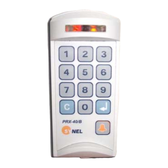
Page 6: Unit Layout
The proximity units enclosure is a sealed IP44 enclosure and contains a small loop antenna, a transmitter and a detector, both connected to a loop antenna. In addition to operating as an access terminal, PRX-40 B includes additional circuitry for storing card- holder data. -
Page 7: Installation
Installation General The PRX-40 B proximity unit is installed at sensitive locations in order to grant access to secure areas. The back panel of the unit serves as an installation template, to mark the location of the screws. Mounting screws and plugs are also provided. -
Page 8: Mounting The Unit
PRX-40B Mounting the unit Select a location for the terminal using the following guidelines for finding the best location: Hold the mounting template to the wall and mark the places to drill holes for the screws and cables. Drill the holes for the connection cable and screws (with 6mm. drill bit). Inset the screw anchors for either plaster or concrete, as needed. - Page 9 PRX-40B 4.3.1 Connect wires The wires are connected to external components as listed in the table below. Connector J5/14 Wire No. Wire Function Present Color Code Vin Power (VCC) Black - TxRx RS-485 Grey + TxRx RS-485 Purple TxD RS -232 White RxD RS -232 Green...
-
Page 10: Connecting To A Master Controller
PRX-40B Wire connection diagram Connecting to a Master controller... -
Page 11: Jumpers
Jumpers Jumper Function Default JP2 (SMD) JP2 closed and JP3 open = Linear decoding Linear JP2 open and JP3 closed = Synel decoding JP3 (SMD) JP4 (SMD) Cross point decoding (currently NA) JP7 (SMD) Connect RS-485 termination resistor Open JP10 (TH) W.D. -
Page 12: Operation
PRX-40B Operation Set-up mode PRX-40/A programming can be divided to three categories: Access Cards configuration (authorized personnel) General definitions Indicator definitions All definitions of Management modes are listed in the table below. The codes in the table below can be used only after completing set-up mode as follows: Step 1: Press 3 times simultaneously on function keys 1 &... - Page 13 PRX-40B Operation mode Card only There is a different Global code only code for Card or code (card no.) each Card and global code employee Card and pin code ----------------------- Card and finger Modes 5-6 only with PrintX Code and finger (finger only) ----------------------- Card and card New master code...
- Page 14 PRX-40B Toggle relay mode 0 - Disable In minutes 0- Disable 1 - Enable Toggle relay timeout 00-99 In seconds 00- Disabled Set reject list flag 1- set with card only mode 0- reset Set/Reset auto finger Version 2.08 with type S. detect reset External magnetic reader...
-
Page 15: Access Cards Configuration
PRX-40B Access cards configuration Time Out After every entry a LED is lit (while waiting for the next entry). After the LED goes out the unit exits the “Programming Mode” and resets (action must be repeated from the beginning). Management of Access Cards (authorized personnel) Managing access Cards can be performed three ways: Using Keyboard - Keying-in the keyboard the card number Using Card - Swiping the card... - Page 16 PRX-40B normal mode. Delete cards: After entering set-up mode key-in code 25 (delete card by index) and key-in a 4 digit index. 2 short beeps will indicate that the index was deleted successfully. After swiping all cards press 7&8 simultaneously (mandatory) (press Enter in terminals that consist of an Enter key) in order to revert to normal mode.
-
Page 17: Communication
PRX-40B 1 = The sensor will function as Normally Closed. Alarm mode Code 51--> 0 = Latch. The alarm does not go off unless it is turned off manually. 1 = Pulse. The alarm goes off after the defined time-out. Alarm pulse activating time Note: Relevant when alarm is in pulse mode. - Page 18 PRX-40B 6.2.1 Communication cables characteristics Follow the listed guidelines when installing the communications cables: The cable should not be installed near EMI factors, such as: • Motors, generators, alternators, and transformers • Air conditioners, elevators • Radio/television transmitters, signal generators and internal communication networks •...
Need help?
Do you have a question about the PRX-40 B and is the answer not in the manual?
Questions and answers