
Subscribe to Our Youtube Channel
Summary of Contents for Red Sound Micro Sync Beat Xtractor
-
Page 1: Midi Clock
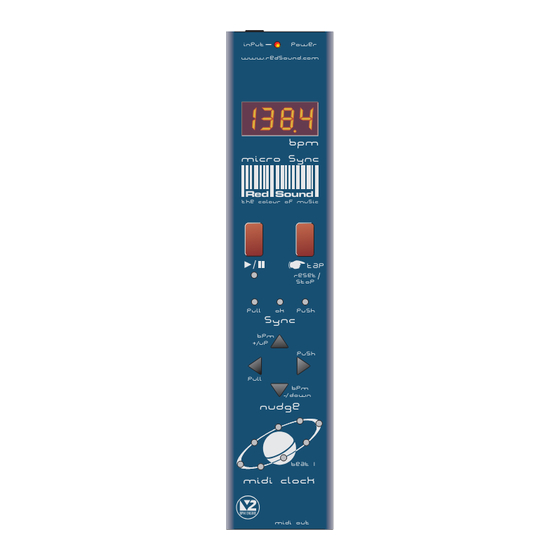
POWER INPUT www.redsound.com 13 8 4 13 8 4 micro sync Red Sound the colour of music RESET STOP PULL PUSH SYNC PUSH PULL down NUDGE BEAT 1 MIDI CLOCK MIDI OUT Issue 3... -
Page 3: Table Of Contents
MICRO SYNC will integrate perfectly into any DJ/studio setup. Please read the following sections of this manual carefully to fully understand the operation of your new RED Sound MICRO SYNC Beat Xtractor. OPERATING CRITERIA This product has been designed to operate most effectively with dance music - i.e. music based on strong regular beats and patterns. -
Page 4: Front Panel/Connectors
See ‘ Setting the correct Input Level ’on page 5. Red Sound POWER IN - Connector the colour of music Connect the output plug of the AC adaptor supplied with the MICRO SYNC to this socket. -
Page 5: Mounting/Connections
MOUNTING/CONNECTIONS MOUNTING THE MICRO SYNC You can choose one of three mounting options included with the MICRO SYNC. M6 SCREW BRACKET Rubber feet - Stick one in each corner on the underside panel for free mounting. M3 SCREW (LENGTH = 6mm MAX) 19”... -
Page 6: External Midi Sequencer Settings
OPERATION EXTERNAL MIDI SEQUENCER SETTINGS Before the MICRO SYNC can operate correctly your MIDI sequencer must first be set to recognise e xternal MIDI Clock commands. Please consult the manufacturers operation manual to make the necessary settings. Here are some typical examples: ROLAND MC-303/505 In System Settings, set the 'SYNCHRONIZATION SETTING' to 'Slave' mode. -
Page 7: Setting The Correct Input Level
OPERATION SETTING THE CORRECT INPUT LEVEL The MICRO SYNC’s input stage will work most effectively when the audio levels within your mixing desk are set to their nominal settings i.e. Individual channel Gain/level controls set to 0dB - Master output fader set to 0dB. The bi-colour ‘INPUT’ indicator at the top of the front panel can show four different input level conditions as follows: - No audio signal present DIM GREEN... -
Page 8: Run/Pause
OPERATION Also, the indicator and ‘Beat 1’ indicator in the MIDI CLOCK display will flash at the detected BPM rate to show ‘PAUSE’ mode. The right-hand digit of the BPM display may fluctuate slightly as the BPM engine constantly analyses and updates the reading in real-time. Any progressive shift in tempo (slowly changing the playback speed using a CD/vinyl deck’s pitch control) should be tracked and displayed by the MICRO SYNC. -
Page 9: Tap (Reset/Stop)
OPERATION This will occur approximately 3-4 seconds after the last valid BPM reading was taken to warn that the MICRO SYNC is now 'free-wheeling' and the BPM display is no longer being updated from the audio track. When the strong regular beats in the audio track return the MICRO SYNC will automatically detect the BPM information and make any necessary adjustments, at which time the flashing decimal point indicators will go out to indicate a 'locked-in' condition. -
Page 10: Sync Indicator
OPERATION SYNC Indicator This 3-way indicator shows beat synchronisation adjustments between the audio track and the MIDI sequencer’s beat position. The MICRO SYNC constantly analyses the accuracy of the relative beat positions and will either 'PULL' or 'PUSH' the MIDI clock output to maintain this synchronisation. - Page 11 OPERATION SYNC Adjustments (using PULL and PUSH buttons): Under normal circumstances the BPM engine will automatically detect and adjust the audio/MIDI trigger point to either the on- beat or off-beat position depending on whichever is more prominent in the audio track. You can use the PUSH/PULL feature to make fine adjustments to the synchronisation (if the MIDI sequencer sounds slightly ahead or behind the beat of the audio) or complete ½...
- Page 12 OPERATION LGH / BAR LGH / BAR Display alternates between PULL PUSH PULL PUSH Further fine adjustments can be made beyond the ‘PULL ½ beat’ point (display reads from ‘-13’ down to ‘-23’) until the synchronisation is pulled back by one complete beat (maximum PULL adjustment).
-
Page 13: Bpm Range
OPERATION Further fine adjustments can be made beyond the ‘PUSH ½ beat’ point (display reads from ‘+13’ up to ‘+23’) until the synchronisation is pushed forwards by one complete beat (maximum PUSH adjustment). For this setting the display will show the following: LGH / BAR LGH / BAR Display alternates... -
Page 14: Hints&Tips / Specification
HINTS&TIPS / SPECIFICATION HINTS & TIPS Tempo Changes: 1. Always make slow changes when adjusting the sound source pitch control. This will allow the MIDI clock to remain in synchronisation during tempo changes. 2. Never make tempo changes during quite passages (when beat information is unavailable) as the MICRO SYNC will lose synchronisation. - Page 15 Cet appareil numerique ne depasse pas les limites de la Classe B au niveau des emissions de bruits radioelectriques fixes dans le Reglement des signaux parasites par le ministere Canadien des Communications. Copyright / Software Copyright / Design Right RED Sound Systems Ltd 2001 Printed in England...
- Page 16 Bourne House, Cores End Road, Bourne End, Bucks. SL8 5AR. England Phone : +44 (0)1628 819191 Fax : +44 (0)1628 819111...
Need help?
Do you have a question about the Micro Sync Beat Xtractor and is the answer not in the manual?
Questions and answers