Advertisement
Quick Links
INSTRUCTIONS SWR/POWER METERS
SX-201, SX-400, SX-601, SX-1000
The SX-201/400 and SX-601 or SX-1000 POWER & SWR meter is the most efficient tool in wide range of semi-professional
measuring and control instruments. Measured values can be easily read in the large scale instruments.
The SX-201/400 and SX-601 or SX-1000 is an insertion type RF wattmeter and can be permanently fitted into a transmission
system for continuous monitoring of station working condition.
The unit can be work without external power supply but with 13.8DC power allows to light up the meter and shows
the active led corresponding to the selected RF coaxial line (for SX-601 and SX-1000)
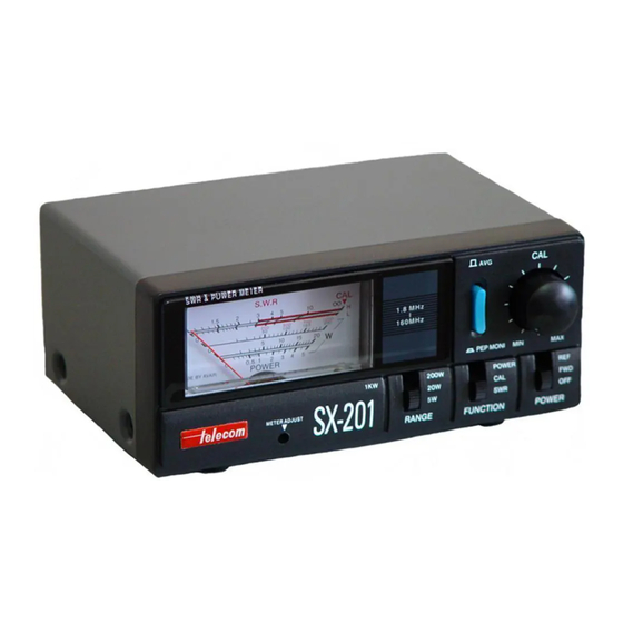
SX-201 & SX-400
SX-601 & SX-1000
DESCRIPTION OF CONTROLS
1. POWER/SWR reading meter
2. Indicator adjustment
3. Power range switch
4. Function switch
5. FWD/Reflected Power/OFF switch
6. SWR calibration potential-meter
7. Average PEP to PEP switch
8. 200W/400W select switch
9. Antenna connector (PL) 1,8-160 MHz.
10. TX connector (PL). 1.8-160 MHz.
11. Power jack (13.8VDC) light up the meter and sensor 1/sensor 2 leds.
12. Antenna connector (N). 140-525 MHz. (SX-601) / 430-1300 MHz. (SX-1000)
13. TX connector (N). 140-525 MHz. (SX-601) / 430-1300 MHz. (SX-1000)
14. Led sensor 1.
15. Led sensor 2.
16. Sensor 1/Sensor 2 switch
Advertisement

Summary of Contents for Telecom SX-201
- Page 1 INSTRUCTIONS SWR/POWER METERS SX-201, SX-400, SX-601, SX-1000 The SX-201/400 and SX-601 or SX-1000 POWER & SWR meter is the most efficient tool in wide range of semi-professional measuring and control instruments. Measured values can be easily read in the large scale instruments.
-
Page 2: Specifications
INSTALLATION To install the SX-201/400 or SX-601/1000 simply connect coaxial cable direct to the antenna connector marked ANT and the cable coming from the transmitter or from the linear amplifier to the connector marked TX. POWER MEASUREMENTS 1. Select the RANGE (3) switch on the end-scale position value as to the power of the unit 2.
Need help?
Do you have a question about the SX-201 and is the answer not in the manual?
Questions and answers