Table of Contents
Advertisement
Quick Links
E 2002 Lennox Industries Inc.
Dallas, Texas, USA
RETAIN THESE INSTRUCTIONS
FOR FUTURE REFERENCE
WARNING
Do not store or use gasoline or other flammable va-
pors and liquids in the vicinity of this or any other ap-
pliance.
WARNING
Improper installation, adjustment, alteration, ser-
vice, or maintenance can cause injury or property
damage. Refer to this manual. For assistance or
additional information, consult a qualified installer
or service agency.
01/04
*2P0104*
INSTALLATION
INSTRUCTIONS
O23 SERIES UNITS
OIL UNITS
504,626M
38152A059
01/04
Supersedes 04/02
Table of Contents
. . . . . . . . . . . . . . . . . . . . . . . . . . . . . . . . . . . . .
. . . . . . . . . . . . . . . . . . . . . . . . . . . . . . . .
. . . . . . . . . . . . . . . . . . . . . . . . . . . . . . .
. . . . . . . . . . . . . . . . . . . . . . . . . . . . .
. . . . . . . . . . . . . . . . . . . . . . . . . . . . . . . . . . . . .
. . . . . . . . . . . . . . . . . . . . . . . . . . . .
. . . . . . . . . . . . . . . . . . . . . . . . . . . . . . . . .
. . . . . . . . . . . . . . . . . . . . . . . . . . . . .
. . . . . . . . . . . . . . . . . . . . . . . . . . . . . . . . . . . .
. . . . . . . . . . . . . . . . . . . . . . . . . . . . .
When venting this appliance, keep vent terminal free
of snow, ice and debris.
General
These instructions are intended as a general guide and do
not supersede local codes in any way. Only qualified tech-
nicians can install and service the Lennox Elite
O23 oil furnaces. In Canada, refer to CSA B139 for recom-
mended installation procedures. Consult authorities who
have jurisdiction before installation.
Never burn garbage or paper in the heating system.
Never leave papers near or around the unit.
Shipping & Packing List
1− Assembled oil furnace
1− Barometric draft control
1− Side exhaust pipe collar
1− Direct intake collar (AFII burner units only)
Check the components for shipping damage. If you find any
damage, immediately contact the last carrier.
Page 1
. . . . . . . . . . . . . . . . . . . . . . . . . .
. . . . . . . . . . . . . . . . . . . . . . . . . . .
. . . . . . . . .
. . . . . . . . . . . . . . . . . . . . .
. . . . . . . . . . . . . . . .
. . . . . . . . . . . . . . . . . . . . . . . .
. . . . . . . . . . . . . . . . .
. . . . . . . . . . .
. . . . . . . . . . . . . . . . . .
CAUTION
CAUTION
504,626M
*P504626M*
Litho U.S.A.
1
1
4
2
2
3
3
5
5
5
6
10
11
12
13
13
15
16
17
®
Series
Advertisement
Table of Contents

Subscribe to Our Youtube Channel
Related Manuals for Lennox O23 SERIES


Summary of Contents for Lennox O23 SERIES
-
Page 1: Table Of Contents
These instructions are intended as a general guide and do not supersede local codes in any way. Only qualified tech- ® nicians can install and service the Lennox Elite Series RETAIN THESE INSTRUCTIONS O23 oil furnaces. In Canada, refer to CSA B139 for recom- mended installation procedures. -
Page 2: O23 Unit Dimensions
O23 Unit Dimensions − Inches (mm) (19) (19) TOP FLUE OUTLET SUPPLY OPENING TOP VIEW FLUE CONNECTION (On Heat Exchanger) SIDE FLUE OUTLET CENTERING HOLE (Field Fabricate Either Side) ELECTRICAL INLET (Right Side Only) (1372) OIL PIPING INLET (Left Side Only) 1-1/2 AIR FLOW OPT. -
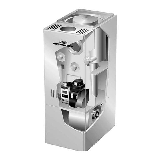
Page 3: O23 Unit Parts Arrangement
O23 Unit Parts Arrangement heat exchanger flue opening clean-out port limit switch clean−out port control box with fan control board observation port Beckettr combustion air intake AFII burner blower motor indoor blower capacitor Figure 1 O23 Oil Burner Parts Arrangement FLANGE ELECTRONIC IGNITION PRIMARY... -
Page 4: Requirements
Clearances 70/105/120 140/154 agency. top of plenum and duct 2 (51) 2 (51) Installation of Lennox oil−fired furnaces must conform with plenum sides 3 (76) 3 (76) the National Fire Protection Association Standard for the sides 0 (0) 0 (0) Installation of Oil Burning Equipment, NFPA No. -
Page 5: Locate & Level The Unit
Once removed, turn the burner around in the vest panel area. Unit Adjustments O23 Series Burner Removal Neither the nozzle setting nor the air adjustments are facto- Loosen three nuts which at- Rotate burner counterclockwise on tach burner to vest panel. -
Page 6: Venting
To check nozzle alignment, again insert the small end into higher temperature rating and is constructed with an inner the end cone and measure the nozzle and electrode align- liner of stainless steel rather than aluminum). ment against the center lines marked on the gauge (again Prior to installation of unit, make a thorough inspection of refer to enclosed illustration sheet). - Page 7 NOTE − If vent pipe needs to exit from side of cabinet, MASONRY CHIMNEY use the pilot hole (located on either side of the unit) to BAROMETRIC cut a 6" (152 mm) round hole. Attach finishing plate LINER CONTROL* (provided) with four sheet metal screws to cover rough (IN EITHER edges.
- Page 8 Combustion Air Requirements Even a small leak around the base of the unit at the platform or at the return air duct connection can cause a potentially CAUTION dangerous negative pressure condition. Air for combustion and ventilation can be brought into the confined space ei- Insufficient combustion air can cause headaches, ther from inside the building or from outside.
- Page 9 ing with the outdoors through horizontal ducts, each open- EQUIPMENT IN CONFINED SPACE ing shall have a minimum free area of 1 square inch (6.4 ALL AIR FROM OUTSIDE square centimeters) per 2,000 Btu (586 W) per total input rating of all equipment in the enclosure (See figure 11). CHIMNEY OR OIL VENT...
-
Page 10: Flue Connections
Horizontal Venting CAUTION The O23 is approved for horizontal venting with the follow- ing mechanical vent systems: DO NOT USE a barometric draft relief in exhaust vent pipe if outdoor combustion air is connected directly Tjernlund (sideshot) #SS1C (Cat. #35E08) or Field Con- to the burner. -
Page 11: Supply & Return Air Plenums
est flue or vent connector, plus 50% of the area of any addi- Radiation Shield Installation tional flues or vent connectors. Install a barometric draft combustible É É É É É É É É material control (provided) and flue pipe according to instructions É... -
Page 12: Oil Supply Line & Filter Connections
Manual bleeding of the fuel pump is required on initial start Oil Piping up. Failure to bleed air from the oil pump could result in an fuel Two-Pipe System air lock/oil starvation condition. Fill Air Vent pump Pipe NOTE − As an extra precaution, cycle heating on and off ten Filter times after bleeding air from the oil pump. -
Page 13: Leak Check
NOTE − An equipment ground screw is provided. Refer Locate filter close to burner for easy maintenance. Table 5 to unit wiring diagram and figure 16 for O23 series lists the filters for the O23 furnace. units. Ground unit using a suitable ground wire. - Page 14 Fan Control Board thermostat terminal strip fan off delay switches Figure 16 Typical O23 Wiring Diagram Figure 17 Page 14...
- Page 15 Typical O23 Wiring Diagram Figure 18 Page 15...
-
Page 16: Unit Start-Up & Adjustments
E − Burner Adjustment CAUTION The following instructions are essential to the proper op- eration of O23 series oil furnaces. To prevent sooting, Do not push the reset button on the primary control more than one time. these instructions must be followed in sequence: 1 −... -
Page 17: Service
This area. will give you the net stack temperature. Use the efficiency charts provided in most CO analyzers to determine fur- NOTE − A heat exchanger clean-out kit ABRSH380 nace efficiency. (35K09) is available from Lennox. Page 17... -
Page 18: Troubleshooting
Troubleshooting Burner failure or improper operation can result from a num- lowing troubleshooting charts list some failures, causes ber of different causes. and a sequence of steps to isolate the point of failure. Often the cause can be pinpointed by observing the differ- Check the simplest and most obvious items before prog- ent types of failure or by the process of elimination. - Page 19 Troubleshooting: Burner fails to start. Source Procedure Causes Correction Thermostat in OFF or COOL Switch to HEAT. Thermostat Check thermostat settings. Turn thermostat to higher tem- Thermostat is set too low perature. Burner motor overload tripped Push reset button pump motor. Check burner motor, primary Primary control tripped on safe- Reset primary control.
- Page 20 Troubleshooting: Burner starts, but no flame is established. Source Procedure Causes Correction Check tank gauge or use dip No oil in tank Fill tank. stick. Coat dip stick with litmus paste If water depth exceeds 1 inch, Oil Supply Water in oil tank and insert into bottom of tank.
- Page 21 Troubleshooting: Burner starts and fires, but lock out on safety. Source Procedure Causes Correction Unbalanced fire Replace nozzle Reduce combustion air − check Too much air − −lean short fire combustion. If burner con- tinues to run, Increase combustion air − check Too little air −...
- Page 22 Troubleshooting: Burner starts and fires, but short cycles (too little heat) Source Procedure Causes Correction Heat anticipator set too low Correct heat anticipator setting. Vibration at thermostat Correct source of vibration. Thermostat Thermostat Check thermostat. Check thermostat. Thermostat in the path of a Shield thermostat from draft or warm air draft relocate.
- Page 23 Troubleshooting: Burner runs continuously (too little heat). Source Procedure Causes Correction Too much combustion air Reduce combustion air. Air leaks into heat exchanger Correct cause of air leak. around inspection door, etc. Low CO Low CO less less Adjust barometric draft con- than 10%.
Need help?
Do you have a question about the O23 SERIES and is the answer not in the manual?
Questions and answers