Table of Contents
Advertisement
Quick Links
Electric Boilers
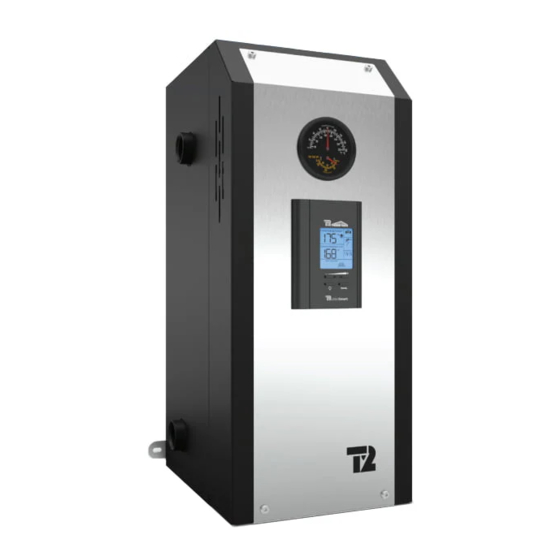
BTH ULTRA
Models ranging from 12 kW to 36 kW 208/240 Volts (1 phase)
INSTALLATION & OPERATION MANUAL
Your BTH ULTRA Electric Boiler has been carefully assembled and factory tested to provide
years of trouble-free service. The following information and safety measures are provided to
enable proper installation, operation, and maintenance of this product.
It is imperative that all persons who are expected to install, operate or adjust this boiler should
read these instructions carefully.
Any questions regarding the operation, maintenance, service or warranty of this electric boiler
should be directed to the supplier.
When all installation steps have been completed, keep this installation manual in a safe place
(close to the boiler) for future reference.
THERMO 2000 INC.
Printed In Canada
BTH ULTRA Electric Boilers Installation & Operation manual (Revision: May 2015)
Revision : May 2015
2
.
Advertisement
Table of Contents

Summary of Contents for Thermo BTH Ultra
- Page 1 Models ranging from 12 kW to 36 kW 208/240 Volts (1 phase) INSTALLATION & OPERATION MANUAL Your BTH ULTRA Electric Boiler has been carefully assembled and factory tested to provide years of trouble-free service. The following information and safety measures are provided to enable proper installation, operation, and maintenance of this product.
-
Page 2: Table Of Contents
5.3 COMPLEMENTARY CHECKS ON DUAL-ENERGY INSTALLATIONS ........21 Section 6 MAINTENANCE ........................22 6.1 INTRODUCTION ......................... 22 6.2 AT ALL TIME..........................22 6.3 TWICE A YEAR........................... 22 6.4 ANNUALY ........................... 22 BTH ULTRA Electric Boilers Installation & Operation manual (Revision: May 2015) - Page 3 Figure 20 : Spare parts (front, 27-29 KW) ....................1 Figure 21 : Spare parts (top, 27-36 KW)....................1 Figure 22 : Spare parts (front, 33-36 KW) ....................1 BTH ULTRA Electric Boilers Installation & Operation manual (Revision: May 2015)
-
Page 4: Section 1: Technical Specifications
Two main terminal blocks that could be converted to one on the job site. Two double pole breakers 1 kW = 3412 Btu BTH ULTRA Electric Boilers Installation & Operation manual (Revision: May 2015) -
Page 5: Table 2 : Boiler Connections And Dimensions (12-24 Kw)
Pressure relief valve 1 ¼“reduced to 3/4 NPTFem Drain valve 1 ¼“reduced to 3/4NPT Fem Shipping weight 75 lbs Item Dimension (inches) 21-1/2 11-3/4 3-1/2 2-3/4 14-1/4 11-5/8 Figure 2 : Boiler dimensions (27-36 KW) 1-3/4 BTH ULTRA Electric Boilers Installation & Operation manual (Revision: May 2015) -
Page 6: Section 2: Introduction
The manufacturer’s responsibility ceases upon delivery of goods to the carrier in good condition. Consignee must file any claims for damage, shortage in shipments, or non- delivery immediately against carrier. BTH ULTRA Electric Boilers Installation & Operation manual (Revision: May 2015) -
Page 7: Section 3: Installation
All models can be installed directly on a combustible wall and into an alcove. The location must have sufficient ventilation to maintain an ambient temperature not exceeding 90°F (32°C). BTH ULTRA Electric Boilers Installation & Operation manual (Revision: May 2015) -
Page 8: Piping Installation
You will find below on figures 4 to 8 the typical piping arrangement for the two main types of installation. The first being as a self-operating unit and the others being connected to an auxiliary boiler in dual- energy. Figure 4 : Typical Installation on heating floor BTH ULTRA Electric Boilers Installation & Operation manual (Revision: May 2015) -
Page 9: Figure 5 : Typical Installation On Fin-Tube Baseboards With Zoning Valves
Figure 5 : Typical installation on fin-tube baseboards with zoning valves Figure 6 : Multi-pump zoning BTH ULTRA Electric Boilers Installation & Operation manual (Revision: May 2015) -
Page 10: Figure 7 : Typical Installation In Dual-Energy Series
Figure 7 : Typical Installation in Dual-Energy Series Figure 8 : Typical installation with three way valve BTH ULTRA Electric Boilers Installation & Operation manual (Revision: May 2015) -
Page 11: Boiler Piping Connection
It is imperative to insure that all air BTH ULTRA Electric Boilers Installation & Operation manual (Revision: May 2015) -
Page 12: Dual Energy Piping
(see table below not external accessories (such as a pump) at giving the amperage drawn by the boiler on each 120Vac. breaker) in conformity with local electrical codes. BTH ULTRA Electric Boilers Installation & Operation manual (Revision: May 2015) -
Page 13: Electrical Supply Of External Accessories
20 ga conductors. Maximum length 100 ft. (33 m). Do not put a jumper between S1&S1 if the outdoor sensor is not used. Figure 9 : Zoning with Multiple pumps BTH ULTRA Electric Boilers Installation & Operation manual (Revision: May 2015) -
Page 14: Dual-Energy Connection With An Auxiliary Boiler
“ELECT” and “Bi-Energ”. Position the switch at “Bi-Energ” Install a 2 wire 18ga cable between the contact (N/F close contact to allow the BTH ULTRA Electric Boilers Installation & Operation manual (Revision: May 2015) -
Page 15: Figure 12 : Connexions With Three Way Valve
It has to be controlled by its own operating and limit controller. Figure 12 : Connexions with three way valve Figure 13 : Wiring diagram (12-24 KW) BTH ULTRA Electric Boilers Installation & Operation manual (Revision: May 2015) -
Page 16: Figure 14 : Wiring Diagram (27-36 Kw)
Figure 14 : Wiring Diagram (27-36 KW) BTH ULTRA Electric Boilers Installation & Operation manual (Revision: May 2015) -
Page 17: Section 4: Adjustment Of The Controller
(Standard parallel Piping system) Two operation modes are then offered: Fixed boiler temperature set point (the outdoor sensor shall not be installed) Outdoor reset Figure 15 : UltraSmart Controller Display BTH ULTRA Electric Boilers Installation & Operation manual (Revision: May 2015) -
Page 18: Operation Of The Interface
A rotation of the stages based on an equal time period of operation is provided. BTH ULTRA Electric Boilers Installation & Operation manual (Revision: May 2015) -
Page 19: Purge Delay Of The Pump
“OFF” The pump will stop immediately when the heat demand has been satisfied. This selection shall be selected on systems equipped with motorised fast closing zone valves in order to prevent noise from water hammering. BTH ULTRA Electric Boilers Installation & Operation manual (Revision: May 2015) -
Page 20: Figure 17 : Back Of The Controller
Select the purge period that the pump will be running once the heat demand is completed. 15 sec. to 60min. 30sec Select OFF if the heat system is equipped with electric zone valves. BTH ULTRA Electric Boilers Installation & Operation manual (Revision: May 2015) -
Page 21: Adjustments Of The Target Temperature By The User
This boiler Press the + - button to select. The controller will register target could simply be gradually increased by pressing BTH ULTRA Electric Boilers Installation & Operation manual (Revision: May 2015) -
Page 22: Operation In Dual-Energy
AUX terminals and it will be the end switch of the valve that will give the signal to the auxiliary boiler to come on. The water flow will then circulate only in the auxiliary boiler. BTH ULTRA Electric Boilers Installation & Operation manual (Revision: May 2015) -
Page 23: Section 5: Start Up Operation
BTH ULTRA Electric Boilers Installation & Operation manual (Revision: May 2015) -
Page 24: Section 6 Maintenance
If the installation includes an auxiliary boiler, have it checked by a qualified technician. BTH ULTRA Electric Boilers Installation & Operation manual (Revision: May 2015) -
Page 25: Section 7- Trouble Shooting
Boiler stays in demand even when -On systems with electric zone -Change defective “end switch”. BTH ULTRA Electric Boilers Installation & Operation manual (Revision: May 2015) - Page 26 1,172 196,358 22,763 4,184 1,073 165,18 19,9 3,76 139,402 17,436 3,383 118,018 15,311 3,05 100,221 13,474 2,754 85,362 11,883 2,49 72,918 10,501 2,255 62,465 9,299 2,045 53,658 8,25 1,857 BTH ULTRA Electric Boilers Installation & Operation manual (Revision: May 2015)
-
Page 27: Spare Parts
3kW : ZEL300-240V3KW (on some Models) 4.5kW : ZEL300-240V45KW ZEL200-DISC227 5kW : ZEL300-240V5KW 6kW : ZEL300-240V6KW High-Limit automatic reset Switch ZEL200-L6C732 Figure 19 : Spare parts (top, 12-24 KW) BTH ULTRA Electric Boilers Installation & Operation manual (Revision: May 2015) - Page 28 4.5kW : ZEL300-240V45KW manual reset switch 5kW : ZEL300-240V5KW (USA Models only) 6kW : ZEL300-240V6KW ZEL200-DISC227 High-Limit automatic reset Switch ZEL200-L6C732 Figure 21 : Spare parts (top, 27-36 KW) BTH ULTRA Electric Boilers Installation & Operation manual (Revision: May 2015)
-
Page 29: Breaker
Transformer 208/240V x 24Vac ZEL400-20842450 (50VA) Power relay 24Vac Fuse ZEL100-24ACNO30 ZEL250-TDMIDJ5 UltraSmart Controller ZEL100-ULTRA 4 poles Contactor 24Vac ZEL100-4P50A24 Breaker ZEL900-2P100A Figure 22 : Spare parts (front, 33-36 KW) BTH ULTRA Electric Boilers Installation & Operation manual (Revision: May 2015) -
Page 30: Bth Ultra Limited Warranty
Limitations Thermo 2000 Inc. shall not be responsible for any damage, loss, and All BTH ULTRA components & parts are warranted for a period of two inconvenience of any nature whatsoever, directly or indirectly, relating (2) years against defects due to defective material or workmanship.
Need help?
Do you have a question about the BTH Ultra and is the answer not in the manual?
Questions and answers