Advertisement
Quick Links
Advertisement

Summary of Contents for Marani DPA-880T
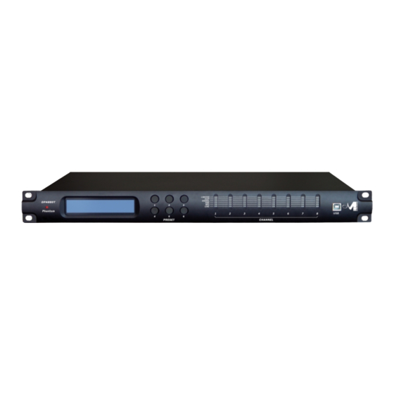
- Page 1 DP A - 8 80T 8 I n - 8 O ut Digital Matrix Mi x er 482mm DIGITAL 19"...
- Page 2 DPA880 Digital 8x8 Conference System Matrix User Manual For the microphone inputs, can be selected a Phantom power Supply. Described below are the functions of the front panel control buttons for the DPA880. • Overview The DPA880 on the front panel offer the possibility to select up to 6 presets, edited and uploaded on the unit through the Pc Sw, thanks to 6 push buttons.
- Page 3 • Getting Started The DPA880 can work as a stand alone unit [Stand Alone Mode], where up to 6 preset can be recalled by directly selecting them through the 6 “preset” buttons available on the front panel, or can work as completely remotely controlled unit [Remote Control Mode]. As soon as is turned ON the device will Load the currently selected preset.
- Page 4 • DPA880 Main Features Maximum Delay: 380.998ms by 21us increment/decrement step, on each Output Parametric Equalization: 3 filters on each Input (when selected Line input or Mic without feedback eliminator active) assignable as Bell or Shelving 5 filters on each Output assignable as Bell or Shelving Filters: Symmetrical Bell or High/Low Shelving up to second order Filter gain:...
- Page 5 • Remote Control Mode The DPA880 is mainly thought to operate with Remote Control Sw running on Pc. Nevertheless, once created the desired presets for the defined applications, the unit can operate as a Stand Alone one, as seen before or as Wall Panel Remote Control working device. The Remote control, when operated by the Wall Panel Remote control, is working on the base of the RS485 connector of the DPA880 The Pc Sw remote control, can instead operate with USB or RS485 connection.
- Page 6 PC Sw Remote Control Operations The DPA880 can be controlled by a Remote Control Sw running on Pc, allowing to fully edit the all processes available on each channel of the DPA880. More, once created the desired configurations and selected the desired processes, the complete channels' set up can be stored within the DPA880 and recalled later on as preset also when the unit is working in Stand Alone Mode or as Wall Control Panel operating unit.
- Page 7 When selected the RS485 connection, more DPA880 can be connected all together. In order this to happen, need the all units (connected in net and up to 32) to be identified by DIFFERENT ID number. In order the units to have a different ID, need to pre-assign to the all units used in net a specific ID number.
- Page 8 Inputs Page From the “Input” Page of the editing environment, on each input can be selected the source. This can be Microphone or Line. When the Line Source is selected, the Input Gain can be adjusted from -127dB up to +6dB. A Bypass button is available for any channel, allowing to “Bypass”...
- Page 9 The DPA880 allows the user to select either Bell or variable Q Shelving Parameters and assign them independently using the 3 available filters. The selection can be done just pressing the “Peak Eq” button on top of the filters' gain sliders and selecting one of the 3 available filters' type: Peaker, variable Q high Shelving and variable Q low Shelving.
- Page 10 Once the all 3 available cursor are shown on the Frequency Response graphic, just selecting anyone of them with the mouse's arrow and maintaining the mouse's click pressed, it is possible to move and place the selected cursor on the desired frequency and with the desired gain. For setting the filter's Q, still need to enter the desired value directly in the dedicated box in the filters' editing main sub-frame.
- Page 11 When the Feedback Eliminator is selected, it can be activated or not, and when active, its speed can be set. The Feedback Eliminator is working on the base of a frequency shift process avoiding the feedback to raise up. The speed of the feedback elimination process it is just defining the amount of frequency shift is added to the input signal.
- Page 12 Outputs Pages From this windows is possible to access and edit the most significant signal processes of the 8 output channels. High Pass Filter: from this sub-frame it is possible to set the Output Channels High Pass Filter (HPF). “Frequency”: (Low Cut frequency) the selectable frequencies range is from 20Hz to 20kHz in steps of 1/24 of an Octave.
- Page 13 Low Pass Filter: from this sub-frame it is possible to set the Output Channels Low Pass Filter (LPF). “Frequency”: (High Cut frequency) the selectable frequencies range is from 20Hz to 20kHz in steps of 1/24 of an Octave. “Slope”: allows you to select the X-Over's Low Pass Filter Shape and Order. The available shapes and orders for the Low Pass Filter are listed below: Bypass (High Pass Filter Bypassed)
- Page 14 The set up of the filters and specially their frequency placement can also be done with the use of the mouse, just activating the “Show Cursor” function, pressing the related button on the left bottom of the frequency response Graphic. Once the all 5 available cursor are shown on the Frequency Response graphic, just selecting anyone of them with the mouse's arrow and maintaining the mouse's click pressed, it is possible to move and place the selected cursor on the desired frequency and with the desired gain.
- Page 15 On each Output channel is available a powerful RMS compressor for improving the sound quality, followed by a Peak limiter useful for limiting the output signal before to enter the amplification system. Each, RMS Compressor and Peak Limiter, can be independently set. The editable parameters can be accessed directly from the RMS Compressor and Peak Limiter sub- frames, or entering a dedicated window accessible from both the sub-frames pressing the buttons “RMS Compressor”...
- Page 16 Peak Limiter – from this sub-frame it is possible to set the Threshold, Attack Time and Release Time of the Output Channels' Peak Limiter. “Threshold”: the selectable range of the Peak Limiter's Threshold is from +18dB (Limiter not active) to -12.0dB in steps of 0.2 dB. “Release Time”: the selectable range of the Peak Limiter's Release Time is from 0.1s to 3s in steps of 0.1s.
- Page 17 Routing Page The routing Page is allowing to set the Matrix Structure of the DPA880 and to assign to each Output the desired Inputs. On the “Output Routing” Matrix block activating the desired “node” will connect the Input and the Output related to the Node.
- Page 18 Overview Page Within the Overview Page, can be checked the all channels inputs selection (between Microphone and Line), so as any of the available processes can be accessed double clicking on its name in the processes' block diagram. Particularly, in this page is also resumed the current selections operated for the Inputs in terms of available Eq or Feedback Eliminator processes, when Microphone Input is selected.
- Page 19 This can be a MARANI or a CUSTOM one. If the MARANI is used, Wall Panel and Pc Remote control can operate in parallel at the same time. If CUSTOM Wall Panel is selected, when used the Pc Sw, the Wall Panel cannot be used.
- Page 20 From the Utilities Window, can be accessed also the all processes for Saving/Recalling presets to/from Pc and to/From the DPA880 and for configuring Special Processes activated by the External Switch Input Ports. Particularly: Load: allows to load on the Pc Remote Control a configuration previously saved on Pc Save: allows to save on Pc the current editing session Store: allows to store on the DPA880, in one of the 6 available location, the current editing session...
- Page 21 Furthermore, it is also possible, in case more Events related to the Input Switches are occurring at the same time, so activating at the same time more than one Switch, to assign a Priority in “serving” the events related to the active Switches (see below). The desired Priority can be set selecting one of the 8 options available, corresponding to the following Priority Table (accessible pressing the “?”...
- Page 22 To anyone of the 4 External Switches (Events) can be related a specific process. This process is corresponding to a Input/Output specific Configuration (Preset), that has to be recalled ONLY if the related Event (Switch Active) is occurring. So, 4 Extra Presets other than the 6 available for the normal operations, can be created and stored, so to be recalled ONLY when the related event is occurring.
- Page 23 DPA880 Technical Specifications ● The DPA880 Digital Speaker Processor is based on a powerful analog and digital DSP platforms having the following specifications Input/Output Stages Maximum Input Level: +18 dBu Maximum Output Level Low: +18 dBu DSP Processing Digital Processing (DSP): Dream SAM3716, 24bit (data) x 96 bit (coeff.), Sw Enhanced Precision Sampling Frequency:...
- Page 24 DPA880 Processes Block Scheme ●...
- Page 25 China Office: 4/5Floor, Building B,No.885,Shenzhou Road,Science City, Guangzhou, China Tel:+86(20)62845258/59/60 MAINS~ Fax:+86(20)62845256 Http:www.marani.com.cn...
Need help?
Do you have a question about the DPA-880T and is the answer not in the manual?
Questions and answers