Table of Contents
Advertisement
Service Literature
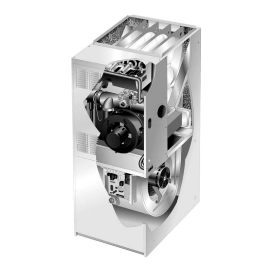
G41UF series units are high−efficiency upflow gas fur
naces manufactured with Lennox DuralokPlust alumi
nized primary and stainless steel secondary clamshell type
heat exchangers. G41UF units are available in heating
input capacities of 44,000 to 132,000 Btuh (12.9 to 38.6 kW)
and cooling applications from 2 through 5 tons (7.0 through
17.6 kW). Refer to Engineering Handbook for proper sizing.
Units are factory equipped for use with natural gas. A kit is
available for conversion to LPG operation. All G41UF
units are equipped with the Lennox SureLight® hot sur
face ignition system. The gas valve is redundant to as
sure safety shut−off as required by C.S.A.
The heat exchanger, burners and manifold assembly can be
removed for inspection and service. The maintenance section
gives a detailed description on how this is done.
Information contained in this manual is intended for use by
qualified service technicians only. All specifications are sub
ject to change. Procedures outlined in this manual are pre
sented as a recommendation only and do not supersede or
replace local or state codes.
Table of Contents
. . . . . . . . . . . . . . . . . . . . . . . . . . . . . . . . . . . . . .
. . . . . . . . . . . . . . . . . . . . . . . . . . . . . . . . .
. . . . . . . . . . . . . . . . . . . . . . . . . . . .
. . . . . . . . . . . . . . . . . . . . . . . . . . . . . . . . . . .
. . . . . . . . . . . . . . . . . . . . . . . . . . . . . . .
. . . . . . . . . . . . . . . . . . . . . . . . . . .
CAUTION
As with any mechanical equipment, personal injury
can result from contact with sharp sheet metal
edges. Be careful when you handle this equipment.
G41UF SERIES UNITS
. . . . . . . . . . . . . . . . . . . . . .
. . . . . . . . . . . . . . . . . . .
. . . . . . . . . . . . . .
. . . . . . . . . . . . . . . . .
. . . . . . . . . . .
Corp. 0303−L2
1
2
3
8
16
Improper installation, adjustment, alteration, service
21
or maintenance can cause property damage, person
al injury or loss of life. Installation and service must
22
be performed by a qualified installer, service agency
26
or the gas supplier.
27
30
35
Electric shock hazard. Can cause injury
or death. Before attempting to perform
any service or maintenance, turn the
electrical power to unit OFF at discon
nect switch(es). Unit may have multiple
power supplies.
Page 1
G41UF
WARNING
WARNING
2003 Lennox Industries Inc.
Litho U.S.A.
Advertisement
Table of Contents

Related Manuals for Lennox G41UF?24B?045


Summary of Contents for Lennox G41UF?24B?045
-
Page 1: Table Of Contents
Units are factory equipped for use with natural gas. A kit is available for conversion to LPG operation. All G41UF units are equipped with the Lennox SureLight® hot sur face ignition system. The gas valve is redundant to as sure safety shut−off as required by C.S.A. -
Page 2: Specifications
SPECIFICATIONS Model No. G41UF−24B−045 G41UF−36B−045 G41UF−36B−070 G41UF−36C−090 G41UF−48C−090 Heating Input − Btuh (kW) 44,000 (12.9) 44,000 (12.9) 66,000 (19.3) 88,000 (25.8) 88,000 (25.8) Performance Performance Output − Btuh (kW) 40,000 (11.7) 40,000 (11.7) 60,000 (17.6) 80,000 (23.4) 80,000 (23.4) AFUE 90.0% 90.0% 90.0%... -
Page 3: Blower Performance Data
SPECIFICATIONS Model No. G41UF−60C−090 G41UF−48C−110 G41UF−60C−110 G41UF−60D−135 Heating Input − Btuh (kW) 88,000 (25.8) 110,000 (32.2) 110,000 (32.2) 132,000 (38.7) Performance Performance Output − Btuh (kW) 80,000 (23.4) 100,000 (29.3) 100,000 (29.3) 120,000 (35.1) AFUE 90.0% 90.0% 90.0% 90.0% High static (CSA) − in. w.g. (Pa) Temperature rise range −... - Page 4 BLOWER PERFORMANCE G41UF−24B−045 PERFORMANCE Air Volume / Watts at Different Blower Speeds External Static External Static Pressure High Medium in. w.g. Watts Watts Watts 0.00 1225 1000 0.10 1190 0.20 1160 0.30 1120 0.40 1070 0.50 1015 0.60 0.70 0.80 0.90 3000 NOTES −...
- Page 5 BLOWER PERFORMANCE G41UF−48C−090 PERFORMANCE Air Volume / Watts at Different Blower Speeds External Static External Static Pressure High Medium−High Medium−Low in. w.g. Watts Watts Watts Watts 0.00 2180 1030 1835 1520 1280 0.10 2135 1005 1825 1510 1275 0.20 2085 1810 1505 1270...
- Page 6 BLOWER PERFORMANCE G41UF−60C−110 PERFORMANCE − Single Side Return Air − Air volumes in bold require field fabricated transition to ac commodate 20 x 25 x 1 in. (508 x 635 x 25 mm) cleanable air filter in order to maintain proper air velocity. Air Volume / Watts at Different Blower Speeds External Static External Static...
- Page 7 G41UF PARTS IDENTIFICATION DuralokPlus HEAT EXCHANGER ASSEMBLY BURNER BOX ASSEMBLY TOP CAP CABINET GAS VALVE AND MANIFOLD COMBUSTION AIR PROVE (PRESSURE) SWITCH FLUE COLLAR WARM HEADER COMBUSTION AIR (COLLECTOR) INDUCER CONDENSER COIL PRIMARY LIMIT BURNER ACCESS COLD HEADER PANEL (COLLECTOR) DOOR INTERLOCK SWITCH...
-
Page 8: I−Unit Components
MAKE−UP result if repair is attempted. 3. Furnace Control (A92) All G41UF model units are equipped with the Lennox Sur eLight ignition system. The system consists of ignition control board (figure 5 with control terminal designations in table 3), ignitor (figure 6) and sensor (figure 7). The... - Page 9 TABLE 1 the control will try four more times with an inter purge and warm−up time between trials of 35 seconds. After a total of SureLight BOARD J156 (J2) TERMINAL DESIGNATIONS five trials for ignition (including the initial trial), the control goes into Watchguard−Flame Failure mode.
- Page 10 4. Ignitor (Figure 6) SURELIGHT INTEGRATED CONTROL BOARD The SureLight ignitor is made of durable silicon nitride. Ig nitor longevity is enhanced by controlling voltage to the ig nitor. The board finds the lowest ignitor temperature which will successfully light the burner, thus increasing the life of the ignitor.
- Page 11 The SureLight board is equipped with two LED lights for troubleshooting. The diagnostic codes are listed below in table 4. TABLE 4 DIAGNOSTIC CODES Make sure to Identify LED’S Correctly. Refer to Installation Instructions for control board layout. LED #1 LED #2 DESCRIPTION Power on −...
- Page 12 G41UF HEATING COMPONENTS LENNOX DURALOKPlust HEAT EXCHANGER (Assembly) CLAMSHELL (Each Segment) CORBEL CUP ROLLOUT SWITCH BURNER BOX ASSEMBLY SURELIGHT IGNITOR LIMIT CONTROL PROVE SWITCH GAS VALVE PROVE SWITCH TUBING WARM END HEADER BOX CONDENSER COIL BACKUP SECONDARY LIMIT COLD END HEADER BOX...
- Page 13 The switch exchangers and exhausted out the exhaust vent pipe. has a different setpoint for each unit model number. See Lennox Repair Parts handbook for set point. TABLE 5 NUMBER OF HEAT...
- Page 14 24VAC terminals and gas control knob are located on 6. Cold End Header Box top of the valve. All terminals on the gas valve are con The cold end header box on the G41UF is a single piece nected to wires from the ignition control. 24V applied to the made of hard plastic.
- Page 15 9. Combustion Air Prove Switch (S18) TABLE 7 G41UF series units are equipped with a combustion air G41UF Unit Set Point prove switch located on the vestibule panel (figure 13). The −045 1.95" switch is connected to the cold end header box housing by −070 1.95"...
-
Page 16: Placement And Installation
7 − Immediately after applying last coat of cement to pipe, BLOWER COMPARTMENT and while both inside socket surface and end of pipe are wet with cement, forcefully insert end of pipe into socket until it bottoms out. Turn pipe 1/4 turn during as sembly (but not after pipe is fully inserted) to distribute cement evenly. - Page 17 1. Choose the appropriate side for venting. Glue the TYPICAL G41UF−60D−135 VENTING field−provided exhaust vent pipe (or provided 2" diam AND CONDENSATE TRAP eter street ell) to the flue collar. Position the exhaust INSTALLATION pipe as close to vertical as possible before transition (Right−Hand Exit Shown Using Provided 2"...
- Page 18 Heating cable installation kit is avail propriate tables in appendix G in the current standards able from Lennox. See Condensate Piping section for part of the National Fuel Gas Code ANSI−Z223.1/NPFA 54 in the U.S.A., and the appropriate Natural Gas and numbers.
- Page 19 IMPORTANT IMPORTANT Exhaust outlet should not be located within 6 feet Do not use screens or perforated metal in exhaust (1.8m) of dryer vent or combustion air inlet or outlet of terminations. Doing so will cause freeze−ups and another appliance. Piping should not exit less than 3 may block the terminations.
- Page 20 Details of Exhaust Piping Terminations for Non Direct 3. If exhaust piping must be run up a side wall to position above snow accumulation or other obstructions, pip Vent Installations. ing must be supported every 3 feet (.9m) as shown in Exhaust pipes may be routed either horizontally through an figure 16.
-
Page 21: Start Up
Use provided HI/LO screws to secure two upper Heating cable kit is available from Lennox in various flanges of the trap to the collar. Use provided sheet lengths; 6 ft. (1.8m) − kit no. 18K48; 24 ft. (7.3m) − kit metal screw to secure bottom trap flange to side of no. -
Page 22: Heating System Service Checks
6 − White Rodgers 36E/36F Gas Valve − Switch gas 11− Set the thermostat to desired setting. valve lever to OFF. See figure 25 for the White Rodg NOTE − When unit is initially started, steps 1 through 11 ers 36F valve and figure 26 for the White Rodgers may need to be repeated to purge air from gas line. - Page 23 TABLE 8 GAS PIPE CAPACITY − FT /HR (kL/HR) Length of Pipe−Feet(m) Nominal Nominal Internal Internal Iron Pipe Size Diameter −Inches(mm) −Inches(mm) (3.048) (6.096) (9.144) (12.192) (15.240) (18.288) (21.336) (24.384) (27.432) (30.480) .364 (6.35) (9.246) (1.13) (.82) (.68) (.57) (.51) (.45) (.42) (.40)
- Page 24 Kitchen detergents can cause harmful corro sion on various metals used in gas piping. Use of a specialty Gas Leak Detector is strongly recommended. It is available through Lennox under part number 31B2001. See Corp. 8411−L10, for further details. WARNING Do not use matches, candles, flame or any other source of ignition to check for gas leaks.
- Page 25 I−Flame Signal Furnace should operate at least 5 minutes before check A transducer (Part #78H5401 available from Lennox Repair ing gas flow. Determine time in seconds for two revolu Parts) is required to measure flame signal if meter used will not tions of gas through the meter.
-
Page 26: Typical Operating Conditions
V−TYPICAL OPERATING CHARACTERISTICS C−External Static Pressure 1 − Measure tap locations as shown in figure 31. A−Blower Operation and Adjustment 2 − Punch a 1/4" diameter hole STATIC PRESSURE NOTE− The following is a generalized procedure and in supply and return air ple TEST does not apply to all thermostat controls. -
Page 27: Maintenance
G41UF BLOWER REMOVAL To Remove Blower: Turn off line voltage power. 1 Disconnect thermostat wiring con nections. 2 Disconnect blower leads from control board. 3 Loosen screws (2) and remove con trol box from unit. Holes are slotted so screws do not need to be removed. 4. - Page 28 5 − Remove sensor wire from sensor. Disconnect 2 pin 22 − Reinstall heat exchanger into cabinet making sure that plug from the ignitor. the clamshells of the heat exchanger assembly are resting on the support located at the rear of the cabi 6 −...
- Page 29 G−Cleaning Burners 7 − Reconnect the sensor wire and reconnect the 2−pin plug to the ignitor wiring harness. 1 − Turn off electrical and gas power supplies to furnace. 8 − Reinstall the burner box assembly using the existing Remove upper and lower furnace access panels. four screws.
-
Page 30: Wiring And Sequence Of Operation
VII−WIRING DIAGRAM AND SEQUENCE OF OPERATION 1 − When there is a call for heat, W1 of the thermostat en 5 − Gas valve opens for a 4−second trial for ignition ergizes W of the furnace control with 24VAC. 6 − Flame is sensed, gas valve remains open for the heat 2 −... -
Page 31: Heating Sequence Of Operation
HEATING SEQUENCE OF OPERATION ABNORMAL HEATING MODE NORMAL HEATING MODE GAS VALVE OFF. COMBUSTION AIR INDUCER OFF. POWER ON INDOOR BLOWER DELAY OFF. LED #1 ON LED #2 ON CONTROL SELF−CHECK OKAY? (RESET CONTROL BY TURNING MAIN POWER OFF.) IS POLARITY REVERSED? POLARITY REVERSED. - Page 32 HEATING SEQUENCE CONTINUED NORMAL HEATING MODE ABNORMAL HEATING MODE 15 SECOND COMBUSTION AIR INDUCER PREPURGE INITIATED BY CLOSED PROVE SWITCH. IS VOLTAGE ABOVE 75 VOLTS? LEDS SIGNAL IGNITOR WARM UP −− 20 SECONDS. ALTERNATING IS THERE A PROPER GROUND? FAST FLASH IS IGNITOR INTACT AND CONNECTED? 4 SECOND TRIAL FOR IGNITION.
- Page 33 COOLING SEQUENCE OF OPERATION NORMAL COOLING MODE ABNORMAL COOLING MODE POWER ON IGNITION CONTROL MAIN POWER ON. GAS VALVE OFF. COMBUSTION AIR INDUCER OFF. INDOOR BLOWER OFF WITH NORMAL DELAY. CONTROL SELF DIAGNOSTIC CHECK. SIGNAL CIRCUIT BOARD FAILURE AT LED. IS CONTROL OPERATING NORMALLY? INTERRUPT MAIN POWER TO RESET CONTROL.
- Page 34 SURELIGHT CONTROL CONTINUOUS HEAT SPEED FAN SEQUENCE OF OPERATION LED: SLOW FLASH RATE REMAINS UNCHANGED THROUGHOUT SEQUENCE. MANUAL FAN SELECTION MADE AT THERMOSTAT. CONTROL (G) ENERGIZES SYSTEM FAN AT HEAT−H HEAT SPEED. EAC−H TERMINAL IS ENERGIZED. HUM−H TERM. ENERGIZES THERMOSTAT CALLS FOR HEAT (W). WITH COMB.
-
Page 35: Troubleshooting
VIII−SURELIGHT CONTROL TROUBLESHOOTING CHART UPON INITIAL POWER UP, REMOVE ALL THERMOSTAT DEMANDS TO THE UNIT PROBLEM: 1 UNIT FAILS TO OPERATE IN THE COOLING, HEATING, OR CONTINUOUS FAN MODE Condition Possible Cause Corrective Action / Comments 1.1.1 ACTION 1 − Check 120V main voltage. −... - Page 36 PROBLEM 1: UNIT FAILS TO OPERATE IN THE COOLING, HEATING, OR CONTINUOUS FAN MODE Condition Possible Cause Corrective Action / Comments ACTION 1 − Check that the unit is properly 1.5.1 ground. − Diagnostic lights flash the improper ACTION 2 − Install a proper main ground to the Improper ground to the unit.
- Page 37 PROBLEM 2: UNIT FAILS TO FIRE IN THE HEATING MODE, COMBUSTION AIR INDUCER DOES NOT ENERGIZE (CONT.). Condition Possible Cause Corrective Action/Comments − Unit operates with a cooling and con 2.3.1 ACTION 1 − Check for correct wiring and loose tinuous fan demand.
- Page 38 PROBLEM 4: UNIT FAILS TO FIRE IN THE HEATING MODE, COMBUSTION AIR BLOWER ENERGIZES, IGNITOR IS ENERGIZED. Condition Possible Cause Corrective Action/Comments ACTION 1 − Check line pressure at the gas valve. 4.1.1 Pressure should not exceed 13" WC for both nat −...
- Page 39 ACTION 2 − Seal leakage if possible, replace secondary heat exchanger, and com heat exchanger if necessary, tag and return heat exchanger to proper Lennox personnel. bustion air blower. 5.3.4 ACTION 1 − Check for sooting deposits or other restrictions in the heat exchanger assembly.
- Page 40 PROBLEM 6: CONTROL SIGNALS LOW FLAME SENSE DURING HEATING MODE Condition Possible Cause Corrective Action/Comments 6.1.1 ACTION 1 − Check the sensor rod for proper loca − Unit operates correctly but the diag tion on the burner. Properly locate the sensor rod Sensor rod is improperly located on or replace if rod cannot be located correctly.
Need help?
Do you have a question about the G41UF?24B?045 and is the answer not in the manual?
Questions and answers