Advertisement
Table of Contents
- 1 Table of Contents
- 2 Introduction
- 3 Safety Information
- 4 Description and Appropriate Use
- 5 Technical Data
- 6 Operation
- 7 Starting up
- 8 Maintenance
- 9 Shutting down
- 10 Technical Faults, Possible Causes and Remedies
- 11 Circuit Diagram - for Specialist Workshop Only
- 12 Customer Service
- 13 Fault Report
- Download this manual
© 2005 Schaudt GmbH, Elektrotechnik & Apparatebau, Daimlerstraße 5, 88677 Markdorf, Germany, Phone +49 7544 9577-0, Telefax +49 7544 9577-29, www.schaudt-gmbh.de
SDT-0018-02EN
(Valid from software version 2.16)
Instruction manual
0
Instruction Manual Control and Switch Panel DT 201 B
Control and switch panel DT 201 B
Table of contents
1
Introduction . . . . . . . . . . . . . . . . . . . . . . . . . . . . . . . . . . . . . . . . . . 2
2
Safety information . . . . . . . . . . . . . . . . . . . . . . . . . . . . . . . . . . . . . 2
3
Description and appropriate use . . . . . . . . . . . . . . . . . . . . . . . . . . 3
4
Technical data . . . . . . . . . . . . . . . . . . . . . . . . . . . . . . . . . . . . . . . . 4
5
Operation . . . . . . . . . . . . . . . . . . . . . . . . . . . . . . . . . . . . . . . . . . . . 5
6
Starting up . . . . . . . . . . . . . . . . . . . . . . . . . . . . . . . . . . . . . . . . . . 19
7
Maintenance. . . . . . . . . . . . . . . . . . . . . . . . . . . . . . . . . . . . . . . . . 20
8
Shutting down . . . . . . . . . . . . . . . . . . . . . . . . . . . . . . . . . . . . . . . 20
9
Technical faults, possible causes and remedies . . . . . . . . . . . . . 21
10
Circuit diagram - for specialist workshop only . . . . . . . . . . . . . . . 22
11
Customer service . . . . . . . . . . . . . . . . . . . . . . . . . . . . . . . . . . . . . 23
12
Fault report. . . . . . . . . . . . . . . . . . . . . . . . . . . . . . . . . . . . . . . . . . 24
830.563
Situation: 18.07.2005
Advertisement
Table of Contents

Subscribe to Our Youtube Channel
Related Manuals for Schaudt DT 201 B

Summary of Contents for Schaudt DT 201 B
-
Page 1: Table Of Contents
Fault report......... . 24 © 2005 Schaudt GmbH, Elektrotechnik & Apparatebau, Daimlerstraße 5, 88677 Markdorf, Germany, Phone +49 7544 9577-0, Telefax +49 7544 9577-29, www.schaudt-gmbh.de SDT-0018-02EN 830.563... -
Page 2: Introduction
Connection work is to be carried out in tensionless condition only. The electrical connection may only be established by qualified person- nel and must be carried out according to the Schaudt installation instructions. If the living area battery is totally discharged or overcharged for a lengthy period, it will be irreparably damaged. -
Page 3: Description And Appropriate Use
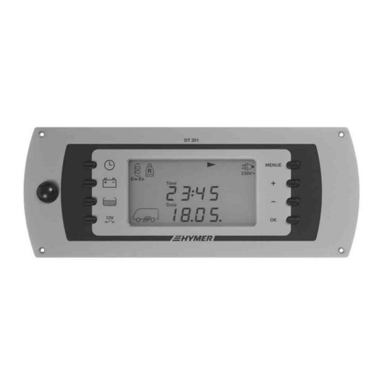
Instruction Manual Control and Switch Panel DT 201 B Description and appropriate use The job of the control and switch panel DT 201 B is to control the electrical functions in the living area of the motorhome and display various values such as capacity, voltages, battery currents and water tank levels. -
Page 4: Technical Data
Instruction Manual Control and Switch Panel DT 201 B Symbols on the display Symbols, measured values and settings of the selected display are indicated in the display window. SDT00094 Fig. 2 Display window 1 Defroster switched on 2 Spare cylinder in use... -
Page 5: Operation
Instruction Manual Control and Switch Panel DT 201 B Operation Switching the 12 V power supply for the living area on and off 12 V main switch button The 12 V main switch button switches all consumers and the control and switch panel on and off. - Page 6 Instruction Manual Control and Switch Panel DT 201 B Spare cylinder (optional) For additional equipment Truma Duomatic L plus: The spare cylinder symbol is displayed when one of the two gas cylinders is empty. The spare cylinder symbol flashes if the second gas cylinder is also empty.
- Page 7 Instruction Manual Control and Switch Panel DT 201 B 5.2.2 Settings in the basic menu The defroster option can be switched on and off in the basic menu. Time, date and nominal battery capacity can also be set and software version and parameter number displayed.
- Page 8 Instruction Manual Control and Switch Panel DT 201 B Defroster unit The defroster unit can be switched on and off or set to automatic operation in the basic menu. Depending on the setting, "ON", "OFF" or "AUTO" is indicat- ed in the display window. This menu is only displayed if the defroster unit is installed.
- Page 9 Instruction Manual Control and Switch Panel DT 201 B Battery display The battery display indicates the battery capacity and the load current of the living area battery as well as the battery voltage of living area battery and starter battery. If available, the solar current of living area battery and starter battery is also displayed.
- Page 10 Instruction Manual Control and Switch Panel DT 201 B The battery capacity can be displayed in ampere hours (Ah) and percent (%). „ Switching between units Press "OK" button. The display of the battery capacity switches between the units ampere hours (Ah) and percent (%).
- Page 11 Instruction Manual Control and Switch Panel DT 201 B The following table will help you correctly interpret the living area battery volt- ages displayed by the control and switch panel. These values apply to actual operation, not off-load voltage and for lead gel batteries only.
- Page 12 Instruction Manual Control and Switch Panel DT 201 B Charge request The batteries should be fully charged every 4 weeks for a long service life. CHARGE ! As a reminder a charge request is displayed 20 days after the last equalising charge.
- Page 13 Instruction Manual Control and Switch Panel DT 201 B 5.3.5 Settings in the battery menu Displaying/setting the The nominal battery capacity "Ah nom" can be adapted e.g. on retrofitting a battery capacity battery. The setting range is between 50 Ah and 495 Ah (K100 value). The standard setting ex works is 90 Ah.
- Page 14 Instruction Manual Control and Switch Panel DT 201 B If the battery voltage remains below 11.0 V, you cannot switch on the 12 V power supply. The battery symbol and "CHARGE !" flash. The battery voltage is also displayed. Fully charge up the living area battery as soon as possible.
- Page 15 Instruction Manual Control and Switch Panel DT 201 B The following table will help you correctly interpret the tank levels indicated by the symbols. Symbol on display Tank level Full or almost full Roughly 3/4 full Roughly 1/2 full Roughly 1/4 full Empty or almost empty 5.5.2...
- Page 16 Instruction Manual Control and Switch Panel DT 201 B Alarm messages Alarm messages are indicated in the basic display by a flashing warning tri- angle and the corresponding symbol. In addition, the display window lights up for 20 seconds. More information on the alarm message is displayed in the battery menu and tank menu.
- Page 17 Instruction Manual Control and Switch Panel DT 201 B 5.7.2 Battery capacity alarm for the living area battery CHARGE ! The battery capacity alarm is triggered when the capacity of the living area battery falls below 15 % of the nominal capacity.
- Page 18 Instruction Manual Control and Switch Panel DT 201 B 5.7.6 Tank alarm If the water tank level falls below 12 % or if the waste water tank level exceeds 87 %, the warning triangle, the word "ALARM" and the tank symbol flash in the basic display.
-
Page 19: Starting Up
Starting up The control and switch panel DT 201 B can only be started up with the Elec- trobloc EBL 101 and the accessories for measuring the water tank levels. -
Page 20: Maintenance
Instruction Manual Control and Switch Panel DT 201 B Maintenance The control and switch panel requires no maintenance. Cleaning Clean the front plate of the control and switch panel with a soft, slightly damp cloth and a mild detergent. Never use spirit, thinners or similar substances. -
Page 21: Technical Faults, Possible Causes And Remedies
Instruction Manual Control and Switch Panel DT 201 B Technical faults, possible causes and remedies If you are unable to solve a fault using the following tables, please contact our customer service address. If this is not possible, e.g. if you are abroad, you can have the control and switch panel repaired at a specialist workshop. -
Page 22: Circuit Diagram - For Specialist Workshop Only
X4 X5 X7 X8 SDT00093 Fig. 7 Circuit diagram for control and switch panel DT 201 B Plug assignment for the X1 ELCO 8263 3 x to gas cylinders X2 ELCO 8263 3 x to gas cylinders circuit plan 1. Negative defroster 1. -
Page 23: Customer Service
Returning a defective device: „ Use ESD protective bag and well-padded packaging. „ If there is no ESD protective bag, ask Schaudt GmbH for a suitable pro- tective bag. „ Fill in and enclose the fault report, see section 12. -
Page 24: Fault Report
Instruction Manual Control and Switch Panel DT 201 B Fault report In the event of damage, please return the defective device together with the completed fault report. Device type: DT 201 B Type no.: (please enter) There is the following defect:...
Need help?
Do you have a question about the DT 201 B and is the answer not in the manual?
Questions and answers