Table of Contents
Advertisement
Available languages
Available languages
Includes: Specifications, Installation and Service Instructions,and Troubleshooting Guidelines
Incluye: Especificaciones, Instrucciones de instalación y mantenimiento, y Guía de resolución de problemas
Owners Manual
Manual del propietario
TM
This system has been
Tested and Certified
by WQA to NSF/ANSI
Standard 44 and ORD
0902 for "Lead Free"
compliance.
Este sistema ha sido
probado y certificado
por la WQA según el
estándar NSF/ANSI
N.° 44 y el ORD 0902
con conformidad "sin
plomo".
12/10
Advertisement
Table of Contents
Troubleshooting

Summary of Contents for Aquanex 36000
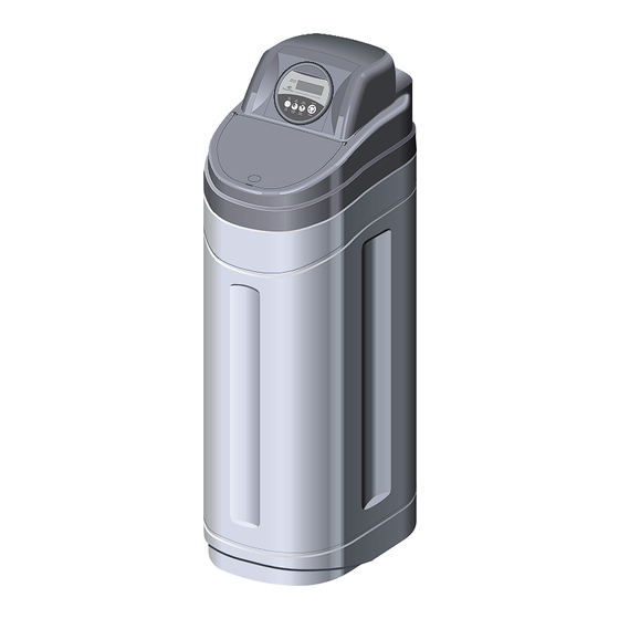
- Page 1 Owners Manual Manual del propietario This system has been Tested and Certified by WQA to NSF/ANSI Standard 44 and ORD 0902 for “Lead Free” compliance. Este sistema ha sido probado y certificado por la WQA según el estándar NSF/ANSI N.° 44 y el ORD 0902 con conformidad “sin plomo”.
-
Page 2: Table Of Contents
TABLE OF CONTENTS Introduction ............................3 Benefits Of Soft/Conditioned Water ....................3 Warnings ............................3 Specifications And Limitations Aqu36 ....................5 Manual Overview ...........................7 Equipment Installation ...........................7 General Warnings And Safety Information Electrical ............... 7 Mechanical ..........................7 Equipment Installation ...........................9 Installation Inspection ........................ - Page 3 ÍNDICE Introducción ............................4 Beneficios Del Agua Suavizada/Acondicionada ................4 Advertencias ............................. 4 Especificaciones Y Limitaciones Del Aqu36 ..................6 Información General Del Manual ......................8 Instalación Del Equipo ...........................8 Advertencias Generales E Información Sobre Seguridad Eléctrica ........8 Parte Mecánica ........................8 Instalación Del Equipo .........................10 Inspección De La Instalación ......................
-
Page 4: Introduction
INTRODUCTION Congratulations! You have purchased one of the highest-quality water softener/conditioner systems available today. Your new water softener/conditioner is very efficient in its salt and water usage. The system is completely automatic and will contribute to better and longer service of all your water using appliances. -
Page 5: Introducción
INTRODUCCIÓN ¡Felicitaciones! Ha adquirido uno de los mejores sistemas de suavizado/acondicionamiento de agua de la actualidad. El consumo de agua y sal de su nuevo suavizador/acondicionador de agua es muy eficiente. El sistema es totalmente automático y hará que todos los aparatos que utilizan agua funcionen mejor y por más tiempo. -
Page 6: Specifications And Limitations Aqu36
SPECIFICATIONS AND LIMITATIONS AQU36 Total Grain Capacity: AQU36 36,000 @ HC Setting @ 17.5 lb of salt 15,900 @ HE Setting @ 3.6 lb of salt Efficiency* 4430 Maximum Water Hardness 99 Grains Per Gallon Maximum Ferrous Iron (“clearwater iron” only)** 1-10 PPM Minimum pH Regeneration Time... -
Page 7: Especificaciones Y Limitaciones Del Aqu36
ESPECIFICACIONES Y LIMITACIONES DEL AQU36 Capacidad total de granos: AQU36 36,000 para la configuración HC y 17.5 lb de sal 15,900 para la configuración HE y 3.6 lb de sal Eficacia* 4430 Dureza máxima del agua 99 granos por galón Hierro ferroso máximo 1 - 10 ppm (sólo "hierro de agua limpia")**... -
Page 8: Manual Overview
MANUAL OVERVIEW HOW TO USE THIS MANUAL This installation manual is designed to guide the installing this equipment should have: installer through the process of installing and • Knowledge in the 706 Logix series starting softeners featuring the 706 Logix series controller and water softener installation controller. -
Page 9: Información General Del Manual
INFORMACIÓN GENERAL DEL MANUAL CÓMO UTILIZAR ESTE MANUAL Este manual de instalación está diseñado para La persona que instalará el equipo deberá tener: guiar al instalador a través del proceso de • Conocimientos sobre el controlador Logix instalación y para poner en funcionamiento los de la serie 706 y la instalación suavizadores que cuentan con el controlador de suavizadores de agua. -
Page 10: Equipment Installation
EQUIPMENT INSTALLATION GENERAL • Observe all warnings that appear in this • Follow state and local codes for water manual. testing. Do not use water that is micro biologically unsafe or of unknown quality. • Keep the unit in the upright position. Do not turn on side, upside down, or drop. -
Page 11: Instalación Del Equipo
INSTALACIÓN DEL EQUIPO GENERAL • Tenga en cuenta todas las advertencias el agua. El tipo de sal aprobado es sal de que figuran en este manual. cloruro de sodio en granos. • Mantenga la unidad en posición vertical. • Siga los códigos locales y estatales No la recueste, no la ponga al revés ni la para evaluar el agua. -
Page 12: System Recharge Cycles
SYSTEM RECHARGE CYCLES 9-CYCLE OPERATION Service (Downflow): Slow Rinse (Downflow): Untreated water is directed down through the The brine is directed down through the resin bed and up through the riser tube. The resin bed and up through the riser tube to hardness ions attach themselves to the resin the drain. -
Page 13: Ciclos De Recarga Del Sistema
CICLOS DE RECARGA DEL SISTEMA OPERACIÓN DE 9 CICLOS Servicio (flujo descendente): Enjuague lento (flujo descendente): El agua sin tratar desciende por el lecho de La salmuera desciende por el lecho de resina y asciende por el tubo vertical. Los iones resina y asciende por el tubo vertical hasta de dureza se adhieren a la resina y se eliminan el desagüe. -
Page 14: Equipment Installation
EQUIPMENT INSTALLATION INSTALACIÓN DEL EQUIPO SYSTEM FEATURES CARACTERÍSTICAS DEL SISTEMA Inlet Entrada Control Outlet Controlador Salida Drain Desagüe Salt Compartment Compartimento de sal Figure 2 Top of Unit Figura 2 Parte superior de la unidad LCD Display Pantalla LCD Time of Day Button Recharge Button Botón Time of Day Botón de recarga... -
Page 15: Instalación Del Equipo
EQUIPMENT INSTALLATION INSTALACIÓN DEL EQUIPO SYSTEM FEATURES CARACTERÍSTICAS DEL SISTEMA Voltage Adapter Input Entrada del adaptador de voltaje Main Motor and Optical Sensor Connection Conexión del motor principal y del sensor óptico Signal Input Entrada de la señal Figure 4 706 Control Back Figura 4 Parte posterior del controlador 706 Inch (mm) Milímetros (pulgadas) -
Page 16: Outdoor Locations
OUTDOOR LOCATIONS It is recommended that the system be installed • Temperature — Extreme hot or cold indoors. When the water conditioning system temperatures may cause damage to the must be installed outdoors, several items must be valve or controller. considered. -
Page 17: Ubicaciones Exteriores
UBICACIONES EXTERIORES Se recomienda instalar el sistema en el interior. Si • Temperatura: las temperaturas extremadamente tiene que instalar el sistema de acondicionamiento frías o calientes pueden dañar la válvula o el de agua en el exterior, deberá tener en cuenta varias controlador. - Page 18 EQUIPMENT INSTALLATION INSTALACIÓN DEL EQUIPO Bath Tub Lavatory Toilet Kitchen Tina de baño Lavabo Baño Cocina Hot Water Outside Outside Outlet Faucet Faucet Salida de agua caliente Grifo Grifo exterior exterior Water Heater Calentador de agua Laundry Tubs Pump or Tuberías del lavadero Meter Bomba del...
- Page 19 18 • 12/10...
- Page 20 WATER LINE CONNECTION Drain Line Línea de desagüe HACIA AFUERA Connector Assembly HACIA ADENTRO Ensamble del conector “H” Clip Sujetador tipo “H” HACIA AFUERA HACIA ADENTRO Handles in Service Handles in Bypass Manijas en posición de servicio Manijas en posición de desvío Figure 9 Series 360 Bypass Operation Figura 9: funcionamiento normal de la derivación de la serie 360 The bypass assembly connects to the water...
- Page 21 CONEXIÓN DE LA TUBERÍA DE AGUA El ensamble de derivación se conecta al Antes de insertar el conector: sistema de agua mediante el ensamble del • Verifique que todas las juntas tóricas estén conector. El conector se asegura a la cañería y en su lugar y no presenten daños.
-
Page 22: Drain Line Flow Control
DRAIN LINE FLOW CONTROL The drain line flow control (DLFC) requires Flow Control Drain Line Clip assembly (Figure 11 Drain Line Flow Control). Control de flujo Sujetador de la línea Locate parts and a roll of Teflon tape. de desagüe (Teflon tape not included) Wrap the tape over threads of the flow control. -
Page 23: Control De Flujo De La Línea De Desagüe
CONTROL DE FLUJO DE LA LÍNEA DE DESAGÜE El control de flujo de la línea de desagüe (DLFC) Enrosque el control de flujo y el codo requiere ensamblado (Figura 11: control de flujo de 90°. Ajuste manualmente. de la línea de desagüe). Coloque el flotador en el control de flujo Tenga a mano las piezas y un rollo de e inserte el ensamble en la abertura de la... -
Page 24: Overflow Line Connection
OVERFLOW LINE CONNECTION In the event of a malfunction, the salt TANK OVERFLOW will direct “overflow” to the drain instead of spilling on the floor. This fitting should be on the side of the cabinet. To connect the overflow line, locate the hole on side of tank. -
Page 25: Conexión Del Tubo De Desbordamiento
CONEXIÓN DEL TUBO DE DESBORDAMIENTO En caso de mal funcionamiento, el de diámetro interno (no provisto) de manera que DESBORDAMIENTO DEL DEPÓSITO de sal se una y se dirija al desagüe. No permita que la directamente rebosará por el desagüe en lugar elevación del tubo de desbordamiento supere al de derramarse en el piso. -
Page 26: Electrical Connection
ELECTRICAL CONNECTION CAUTION: This valve and control are for dry 120 Vac Adapters: location use only unless used with a Listed Make sure power source matches the rating Class 2 power supply suitable for outdoor printed on the AC adapter. use. -
Page 27: Conexión Eléctrica
CONEXIÓN ELÉCTRICA PRECAUCIÓN: Esta válvula y este controlador Adaptadores de 120 V de CA: sólo se pueden utilizar en lugares secos, a Asegúrese de que la fuente de alimentación menos que los utilice junto con un suministro sea equivalente a la potencia impresa en el eléctrico de Clase 2 apto para uso exterior. -
Page 28: General 706 Series Instructions
GENERAL 706 SERIES INSTRUCTIONS 706 SERIES CONTROLLER Power Loss Memory Retention Motor The 706 Series controllers feature battery-free The 706 series controller uses a standard time and date retention during the loss of power. 12-volt AC motor. This is designed to last a minimum of 8 hours Power depending on the installation. -
Page 29: Instrucciones Generales De La Serie 706
INSTRUCCIONES GENERALES DE LA SERIE 706 CONTROLADOR DE LA SERIE 706 Retención de memoria tras un corte Motor de energía El controlador de la serie 706 utiliza un motor estándar de 12 voltios de CA. Los controladores de la serie 706 pueden retener fechas y horarios sin ayuda de la batería Suministro eléctrico en el caso de cortes de energía. -
Page 30: Display Icons 706 Controller
DISPLAY ICONS 706 CONTROLLER X100 Figure 17 Display Icons Figura 17 Íconos de pantalla NOTE: In normal operation and during The recycle sign is displayed (flashing) programming, only a few of the icons will when a recharge at the next time of actually be displayed. -
Page 31: Íconos De Pantalla Del Controlador 706
ÍCONOS DE PANTALLA DEL CONTROLADOR 706 NOTA: Durante el funcionamiento normal y la El símbolo de reciclado se muestra programación, sólo se mostrarán algunos íconos. (parpadea) cuando se necesita una Cuando aparece en la pantalla indica el próxima recarga. También se visualiza flujo de agua. -
Page 32: Keypad - Buttons
KEYPAD - BUTTONS Figure 18 Keypad Buttons Figura 18 Botones del teclado Time of Day - Press and release to display Recharge - Press and release to initiate a the time of day for five seconds. Press recharge. A recharge will start at the next button again while current time is displayed scheduled time of recharge (12:00 AM). -
Page 33: Botones Del Teclado
BOTONES DEL TECLADO Hora del día: presione y suelte para Recarga: presione y suelte para iniciar visualizar la hora del día durante la recarga. La recarga comienza en la cinco segundos. Presione el botón siguiente hora programada de recarga nuevamente mientras se muestra la hora (12:00 a. -
Page 34: Recharge
RECHARGE During a Recharge: • Press and hold Time of Day and Recharge for 3 seconds to advance through all • Total regen time remaining is displayed remaining recharge cycles. on screen. Hourglass will flash. • The recharge icon is on steady. Camshaft will advance to service - may take 1 to 2 minutes. -
Page 35: Recarga
RECARGA Durante la recarga: • Mantenga presionado los botones Hora del día y Recarga durante 3 segundos para • El tiempo total restante de regeneración se avanzar por los ciclos de recarga restantes. muestra en la pantalla. El reloj de arena parpadeará. •... -
Page 36: 706 Series Initial Power-Up
706 SERIES INITIAL POWER-UP The water supply valve should be off or the Short term memory will hold settings for valve is in by-pass approximately eight hours. Settings include: • Water used today Initial Power-Up - (Camshaft proceeds to • Water used since last recharge HOME position) •... -
Page 37: Puesta En Marcha Inicial De La Serie 706
PUESTA EN MARCHA INICIAL DE LA SERIE 706 Deberá cerrarse la válvula del suministro de La memoria de corto plazo retiene las agua o, de lo contrario, la válvula se derivará. configuraciones aproximadamente durante ocho horas. Las configuraciones incluyen: Puesta en marcha inicial (el árbol de •... - Page 38 STEP 2 SET SALT SETTING The controller starts (defaults) with the HE HE this setting minimizes salt used for a (high efficiency) setting. If you want to check recharge (uses the least amount of salt) and or change the setting, press the Salt Amount provides the least amount of water between button to display the current setting.
- Page 39 PASO 2: CONFIGURACIÓN DE SAL El controlador se inicia (de forma del sistema entre cargas y utiliza más sal. predeterminada) en la configuración HE (alta Puede utilizar esta configuración si tiene agua eficacia). Si desea corroborar o modificar la muy dura o utiliza mucha agua. configuración, presione el botón Cantidad de HE: esta configuración minimiza el uso de sal sal para visualizar la configuración actual.
-
Page 40: Placing Softener Into Operation
PLACING SOFTENER INTO OPERATION After you have performed the previous initial • There is no salt in the tank. power-up steps, you will need to place the • The controller is on and has been softener into operation. Follow these steps programmed following the three steps. -
Page 41: Puesta En Marcha Del Suavizador
PUESTA EN MARCHA DEL SUAVIZADOR Una vez realizados los pasos de puesta en • El depósito no tiene sal. marcha inicial arriba mencionados, deberá • El controlador está encendido y se poner en marcha el suavizador. Siga los ha programado según los tres pasos siguientes pasos detenidamente. -
Page 42: Things You Might Need To Know
PLACING SOFTENER INTO OPERATION The repressurize cycle is short and allows Fill the salt tank with softener salt. The display internal system pressures to stabilize. After should be showing the current time of day and 1-2 minutes advance to the next cycle. the colon will be flashing. -
Page 43: Datos Útiles
PUESTA EN MARCHA DEL SUAVIZADOR 11. El segundo enjuague rápido es el último ciclo del proceso de recarga. La descarga al desagüe será rápida. Este ciclo dura 1 minuto. Permita que finalice y prosiga con el modo de servicio.El controlador se iniciará por primera vez conforme a la recarga programada para comenzar según el período habitual de recarga. -
Page 44: Accessing History Values
ACCESSING HISTORY VALUES Accessing History Values Code Description Notes The 706 control features a review level that displays the operation history of the system. Days since last Days since last recharge recharge This is a great troubleshooting tool for the control valve. -
Page 45: Acceso Al Historial De Valores
ACCESO AL HISTORIAL DE VALORES Acceso al historial de valores Código Descripción Notas El controlador 706 presenta un nivel de revisión que muestra el historial de operaciones del Días desde la última Días desde la última recarga recarga sistema. Es una excelente herramienta de resolución de problemas de la válvula de control. -
Page 46: Use And Care
USE AND CARE Type of System Resetting the Control After a Power Outage Your water softener is a fully automatic Demand The only correction necessary after a power Initiated, metered system. This means the outage is resetting the time of day. All other softener meters or keeps track of the water settings are retained in the control memory and used in the home. -
Page 47: Uso Y Mantenimiento
USO Y MANTENIMIENTO Tipo de sistema Reinicio del controlador tras un apagón eléctrico Su suavizador de agua es un sistema automático La única corrección necesaria tras un apagón que mide la demanda. Esto significa que mide eléctrico es reiniciar la hora del día. Todas o registra el consumo de agua de la vivienda. -
Page 48: Sodium Added To Water From Cation Exchange Softening
SODIUM ADDED TO WATER FROM CATION EXCHANGE SOFTENING Initial feed water hardness Sodium added by softening Potassium added by softening Dureza inicial en el agua entrante Sodio adherido por suavizar Potasio adherido para suavizar (grains per gallon) (granos por galón) (milligrams/miligramos Na+/qt.) (milligrams/miligramos K+/qt.) 62.9... -
Page 49: Sodio Agregado Al Agua Por El Suavizado Mediante El Intercambio De Cationes
SODIO AGREGADO AL AGUA POR EL SUAVIZADO MEDIANTE EL INTERCAMBIO DE CATIONES Initial feed water hardness Sodium added by softening Potassium added by softening Dureza inicial del agua entrante Sodio agregado por el suavizado Potasio agregado por el suavizado (grains per gallon) (granos por galón) (milligrams/miligramos Na+/cuarto de galón) (milligrams/miligramos K+/cuarto de galón) 62.9... -
Page 50: Tank Assembly
TANK ASSEMBLY Item Part No. Description 1 ..1 ..4000512 ....Tank Brine 2 ..1 ..4000505 ....Housing 3 ..1 ..4000506 ....Lid 4 ..1 ..4000853 ....Latch 5 ..1 ..4001126 ....Controller, 706 6 ..1 ..CH20090-7 ..Resin Tank 7 ..1 ..CH20795 .....Brine Tube Assembly 8 .. -
Page 51: Ensamble Del Depósito
ENSAMBLE DEL DEPÓSITO N.º de Cantidad N.º de pieza Descripción elemento 1 ......1 ......4000512 ......Depósito de salmuera 2 ......1 ......4000505 ......Carcasa 3 ......1 ......4000506 ......Tapa 4 ......1 ......4000853 ......Pasador 5 ......1 ......4001126 ......Controlador 706 6 ......1 ......CH20090-7 .......Depósito de resina 7 ......1 ......CH20795 ......Ensamble del tubo de salmuera 8 ......1 ......4000513 ......Abrazadera del depósito de resina 9 ......1 ......4000514 ......Abrazadera del tubo del flotador... -
Page 52: Valve Assembly
VALVE ASSEMBLY Item Part No. Description Item Part No. Description 1 ..1 ..3019151 ....120 VAC, 60 Hz, N. 19 ..1 ..1235446 ....Assembly, Sensor America Cable Plug, Energy Star 20 ..1 ..3031825 ....Kit, O-ring, Manifold 2 ..1 ..4000889 ....Valve Body Assy, 21 .. -
Page 53: Ensamble De La Válvula
ENSAMBLE DE LA VÁLVULA N.º de Cantidad N.º de pieza Descripción elemento 1......1 ....3019151 ....120 V CA, 60 Hz, enchufe para América del Norte, Energy Star 2......1 ....4000889 ....Ensamble del cuerpo de la válvula; el controlador volumétrico incluye el elemento N.º 18 3......1 ....3007947 ....Juego de discos de válvula 4......1 ....3022012 ....Placa superior 5......1 ....1235373 ....Sensor óptico... -
Page 54: Brine Well Assembly Ch15675
BRINE WELL ASSEMBLY CH20795 Item Part No. Description Not Shown 1 ..CH20774 .....Overflow Fitting 1 ..1 ..CH15013-1 ..Brine Well w/Slots Assembly 2 ..1 ..CH15062 .....Safety Brine Valve 1 ..*CH15031-1..Overflow Elbow 3 ..2 ..CH15070 .....Grammet 1 ..*CH15031-2..Overflow Nut 4 .. -
Page 55: Ensamble Del Depósito De Salmuera Ch15675
ENSAMBLE DEL DEPÓSITO DE SALMUERA CH20795 N.º de Cantidad N.º de pieza Descripción elemento 1 ....1 ....CH15013-1 ..... Depósito de salmuera con ranuras 2 ....1 ....CH15062 ....Válvula de seguridad de la salmuera 3 ....2 ....CH15070 ....Arandela 4 .... -
Page 56: System Troubleshooting Guide
SYSTEM TROUBLESHOOTING GUIDE System WARNING: Service procedures that require the water pressure to be removed from the system are marked with an “!” after the possible cause. To remove water pressure from the system, put the bypass valve or three-valve bypass into the bypass position and open the backwash drain valve (the seventh valve back from the control) with a screwdriver. -
Page 57: Guía De Resolución De Problemas Del Sistema
GUÍA DE RESOLUCIÓN DE PROBLEMAS DEL SISTEMA Sistema ADVERTENCIA: Los procedimientos de mantenimiento que requieren la eliminación de la presión de agua del sistema se marcan con el signo "!" a continuación de la causa posible. Para eliminar la presión de agua del sistema, coloque la válvula de derivación o la válvula de derivación triple en la posición de desvío y abra la válvula de desagüe del lavado a contracorriente (la séptima válvula del controlador) con un destornillador. -
Page 58: Aqu36 706 Control Troubleshooting Guide
AQU36 706 CONTROL TROUBLESHOOTING GUIDE The AQU36 continuously monitors itself and numbers, a description of each error, the cause sounds an alarm if it detects something wrong. of the error, and the solutions. To silence the The alarm is a beep that is on for one second alarm, press any button on the control. -
Page 59: Guía De Resolución De Problemas Del Controlador 706 Del Aqu36
GUÍA DE RESOLUCIÓN DE PROBLEMAS DEL CONTROLADOR 706 DEL AQU36 AQU36 continuamente se autocontrola y hace enumera los números de error, la descripción sonar una alarma si detecta que algo funciona de cada uno de ellos junto con sus causas y mal. -
Page 60: Performance Data Sheet
PERFORMANCE DATA SHEET AMERIFLOW 20-1200-AQU36 WATER SOFTENER SYSTEM PERFORMANCE DATA SHEET Model 20-1200-AQU36 Rated Service Flow (gpm) 11.0 Pressure Drop at Rated Service 14.0 Flow Rate (psid) Rated Capacity 15,931 @ 3.6 (grains @ lb of salt) 36,089 @ 17.5 Rated Efficiency 4,426 lbs salt @ 3.6 lbs (grains/lb Salt @ lb of salt) -
Page 61: Hoja De Datos De Rendimiento
HOJA DE DATOS DE RENDIMIENTO HOJA DE DATOS DE RENDIMIENTO DEL SISTEMA DE SUAVIZADO DE AGUA AMERIFLOW 20-1200-AQU36 Modelo 20-1200-AQU36 Capacidad del caudal en funcionamiento (gpm) Caída de presión con capacidad del caudal en funcionamiento (psid) Capacidad nominal 15.931 cada 3,6 (granos cada lb de sal) 36.089 cada 17,5 Eficacia nominal... -
Page 62: Warranty
MANUFACTURERS WARRANTY WATER SOFTENER/CONDITIONER LIMITED WARRANTY Your Water Softener/Conditioner System is warranted to the original owner from date of purchase, as indicated below. Factory labor, (trip charge not included), to repair or replace defective component(s) is covered for: Model AQU36 1-year from date of purchase The resin is warranted to be free from material defects for (warranty void if source water exceeds 3ppm chlorine): Model AQU36... -
Page 63: Garantía
GARANTÍA DEL FABRICANTE SUAVIZADOR/ACONDICIONADOR DE AGUA GARANTÍA LIMITADA La garantía del sistema de suavizado/acondicionado se extiende al propietario original a partir de la fecha de compra, como se indica a continuación. La cobertura de la mano de obra industrial para la reparación o sustitución de componentes defectuosos (no incluye costos de envío) dura: Modelo AQU36 1 año a partir de la fecha de compra... - Page 64 WARRANTY REGISTRATION CARD Mail form and a copy of original sales receipt to: AmeriFlow™ Water Systems Inc., 525 W. 21 St. Tempe, AZ 85282 U.S.A. Or fax form and a copy of original sales receipt to: (602) 244-2505 AmeriFlow™ Water Systems Inc. considers the safety of your personal information very important. AmeriFlow™...
- Page 65 TARJETA DE REGISTRO DE LA GARANTÍA Envíe el formulario y la copia del recibo de compra original por correo a: AmeriFlow™ Water Systems Inc., 525 W. 21 St. Tempe, AZ 85282 U.S.A. O envíe el formulario y la copia del recibo de compra original por fax al: (602) 244-2505 AmeriFlow™...
- Page 66 36k of cation resin Capacidad de 36,000 de cationes de resina www.aquanexwater.com 4000873 Rev B 1-888-579-PURE 65 • 12/10...
- Page 67 Owners Manual Manual del propietario This system has been Tested and Certified by WQA to NSF/ANSI Standard 44 and ORD 0902 for “Lead Free” compliance. Este sistema ha sido probado y certificado por la WQA según el estándar NSF/ANSI N.° 44 y el ORD 0902 con conformidad “sin plomo”.
Need help?
Do you have a question about the 36000 and is the answer not in the manual?
Questions and answers