Table of Contents
Advertisement
Advertisement
Table of Contents

Summary of Contents for Honda Electronics HE-6801
- Page 2 INTRODUCTION We thank you very much for your purchasing our product HE-6801/HE-6802/HE-6901/HE-6902. Please be sure to read this operation manual carefully and understand what it describes before you operate this unit in order to keep your safety. After you read this manual, please keep it at the place where you will not lose or break so as to read soon when it is necessary.
-
Page 3: Table Of Contents
CONTENTS CAUTION ON SAFETY (PLEASE MAKE SURE TO READ.) 1. HANDLING OF MAIN UNIT 2. HANDLING OF CABLES 3. HANDLING OF TRANSDUCER AND WATER TEMPERATURE SENSOR 4. HANDLING OF REMOTE 5. HANDLING OF GPS ANTENNA 6. TFT LCD PANEL 7. CAUTION ON OPERATION FEATURES DESCRIPTIONS 1. - Page 4 TO ERASE WAKE TO MEMORIZE (SHOW) WAYPOINT MARK TO ERASE WAYPOINT MARK TO EDIT WAYPOINT MARK TO SET WAYPOINT NAVIGATION TO CLEAR WAYPOINT NAVIGATION TO DRAW LINE TO ERASE LINE TO REGISTER (ERASE) ROUTE TO RECALL REGISTERED ROUTE (SETTING ROUTE NAVIGATION) TO ADVANCE WAYPOINT/TO RETURN WAYPOINT TO SHOW ISOBATH TO INDICATE PLACE NAME OTHER NAME FISH SHOAL LIGHT...
- Page 5 OPERATION OF FISH FINDER (FOR ONLY HE-6801, HE-6901) HOW TO SEE THE DISPLAY OF FISH FINDER MODE TO SET THE DEPTH (DISPLAY RANGE) TO ADJUST SENSITIVITY TO SET SHIFT (DISPLAY RANGE SHIFT) TO MOVE EXPANDED AREA TO SHOW/SET THE EXPANSION MODE TO SET WATER TEMP.
- Page 6 REFERENCE DIMENSIONAL DRAWING WIRING DIAGRAM CONNECTING DIAGRAM INSTALLATION OF MAIN UNIT AND DISPLAY MOUNTING THE GPS ANTENNA INSTALLATION OF TRANSDUCER (THRU-HULL) INSTALLATION OF WATER TEMP. SENSOR STANDARD COMPOSITION GENERAL INFORMATION OF FISH FINDER TROUBLE SHOOTING SPECIFICATIONS...
-
Page 7: Caution On Safety (Please Make Sure To Read.)
1. CAUTION ON SAFETY (PLEASE MAKE SURE TO READ.) This section explains the important cautions in order to prevent the person who will use our product or other persons from human damage or damage to their property. 1. HANDLING OF MAIN UNIT DANGER High voltage is applied to the inside of unit. -
Page 8: Handling Of Cables
AUTION Do not install at the place where rain or spray dashes directly. (It is not water- proof.) It causes to firing, human damage or electric shock due to increasing temperature inside the unit. Do not install at the place where it becomes hot. It causes to firing, human damage or electric shock due to increasing temperature inside the unit. -
Page 9: Handling Of Transducer And Water Temperature Sensor
3. HANDLING OF TRANSDUCER AND WATER TEMPERATURE SENSOR DANGER Work on the board is too unstable and risky. Installation and maintenance of transducer and water temperature sensor should be done after you land and fix the boat. Unless you keep it, human damage resulting in death or serious wound will occur. -
Page 10: Handling Of Remote
4. HANDLING OF REMOTE DANGER Do not use leaked battery. (When using wireless remote) When leaked liquid stains on body, it causes to damage. In case of staining, wash out with clean water immediately. CAUTION Keep at the place where it will not drop due to vibration ,etc. when it is not used. It causes to accident like human damage. -
Page 11: Tft Lcd Panel
6. TFT LCD PANEL As TFT LCD panel is made with high precision technology, over 99% is effective pixel but less than 0.01% pixel is lacked or there exists pixel light always. It is not trouble. Please understand it in advance. 7. -
Page 12: Features
FEATURES Process of drawing coastlines at high speed! High performance CPU enables you to draw coastlines at high speed. Possible to install at free location! You can install the display in both width and length as well as you can change the display Portrait or Landscape. -
Page 13: Descriptions
Ground Terminal Antenna Display Display Power Supply (5P) To Video Signal Cable Display DC Power Supply (2P) OP Display (5P) Transducer External Output (6P) 5P is used for 50kHz-200kHz Remote for OP display (4P) (only HE-6801, HE-6901) <Rear of main unit/Connection>... -
Page 14: Remote
Power ( page14) Show event mark on the display. Power ON/OFF WP RECALL ( page37) Mode Selection ( page14) Recall waypoint. (for only HE-6801,HE-6901) WP SAVE ( page33) It switches Fish Finder mode and Store waypoint. Plotter mode. EVENT MARK ( page26) Quick Range ( page21) Enter event mark on the display. - Page 15 HANDLING OF REMOTE WARNING Do not use leaked battery. (When using wireless remote) When leaked liquid stains on body, it may cause to damage. In case of staining, wash out with clean water immediately. CAUTION Keep at the place where it will not drop due to vibration ,etc. when it is not used. It causes to accident like human damage.
- Page 16 [CAUTION ON REMOTE] Take care not to hit with strong light like direct sun ray on infrared rays sensor of main unit. In some case you can not operate the key on remote. Take care not to put the obstacles between remote and infrared rays sensor.
-
Page 17: How To See The Display
5 ALARM 6 CHANGE OF SHAPE 6 READOUT SETTING 7 LIST/EDIT 7 INFO MODE DISPLAY 0/1000 USED 8 OTHERS 9 SOUNDER Display is HE-6801 or HE-6901’s. On HE-6802 or HE-6902, fish finder display on right side of screen is not shown. -
Page 18: How To Operate Menu
HOW TO OPERATE MENU How to operate menu You can change contents of item which you set by selecting menu item using [MENU] key, [CENTER] key, [SET] key and [CLR] key. Press [MENU] key. Instead of right of [CENTER] key, Select desired item turning [CENTER] key same operation is available by pressing [SET] key or Center of... -
Page 19: Basic Operation
BASIC OPERATION POWER ON/OFF HOW TO CHANGE FISH FINDER/PLOTTER MODE TO CHANGE DISPLAY STYLE (PORTRAIT/LANDSCAPE) TO CONTROL BRIGHTNESS OF SCREEN TO SHOW SIMULATION DISPLAY... -
Page 20: Power On/Off
Fish Finder key Fish Finder/Plotter key CENTER key Change by pressing either key ([S], [S+PL],[PL]). (for only HE-6801 and HE-6901) Fish finder mode is shown. [S+PL] Plotter mode is shown on left of screen and fish finder mode is shown on right of screen. -
Page 21: To Change Display Style (Portrait/Landscape)
TO CHANGE DISPLAY STYLE (PORTRAIT/LANDSCAPE) To change display style (Portrait/Landscape) You can change the display (landscape, portrait, landscape reverse and portrait reverse) according to the status of installing the unit. Select [8.OTHERS] [8.INITIAL] [6.PICTURE STYLE] on menu. Select [6.PICTURE STYLE] according to the status of installing the unit. -
Page 22: To Show Simulation Display
TO SHOW SIMULATION DISPLAY TO SHOW SIMULATION DISPLAY This unit has internal simulation. Even if you do not connect with GPS or transducer, you can practice the operation, etc. Select [8.OTHERS] [8.INITIAL] SIMULATION] on menu. Select item by [CENTER] key and press [SET] key. -
Page 23: Operation Of Plotter
OPERATION OF PLOTTER HOW TO USE THE CURSOR TO MOVE THE DISPLAY TO ENLARGE/REDUCE THE PICTURE TO SELECT THE DISPLAY DIRECTION TO SET RANGE YOU ALWAYS USE TO USE MAP CARD TO USE MEMORY CARD TO ENTER EVENT MARK TO ERASE EVENT MARK TO EDIT EVENT MARK TO SHOW (RECORD) WAKE TO ERASE WAKE... -
Page 24: How To Use The Cursor
HOW TO USE THE CURSOR ON/OFF of Cursor Following operations are available by cursor. Latitude/longitude at optional position of CURSOR ON/OFF key display are shown. Distance, direction and required time from own boat position to cursor are shown. Enter/erase of event marks , waypoints, etc. -
Page 25: To Move The Display
TO MOVE THE DISPLAY Movement of display CURSOR ON/OFF key Erase the cursor by pressing [CURSOR ON/OFF] key. Display moves up/downward or left/right by turning [CENTER] key. [Movement of display] When own boat marker is out of screen, it moves map automatically so that own boat marker is always indicated at center of screen in case that [6.READOUT SETTING] [1.MAP READOUT]... - Page 26 [Scale] “SCALE” helps you to know the distance on the screen. Color of range and scale are same as wake’s. In case of single map display Display expands by pressing [EXP] key. Display reduces by pressing [RED] key. In case of dual map display Range Scale Display expands by pressing [EXP] key.
-
Page 27: To Select The Display Direction
TO SELECT THE DISPLAY DIRECTION Selection of direction NORTH UP key Either North Up or Course Up is selected by pressing [NORTH UP] key or [COURSE UP] key. [North Up] :Just upper of display becomes “North”. [Course Up] :Just upper of display becomes “Bearing of own boat”. -
Page 28: To Use Map Card
TO USE MAP CARD Coastline Data There are two map slots (upper and lower). In case of inserting two map cards, first priority is given to map card in upper slot. [Inserting Card] Cover Insert card into slot while sticker side faces up. Be sure to face sticker side of map card (memory card) up. -
Page 29: To Use Memory Card
TO USE MEMORY CARD Copy of data [Memory Card] Contents set in the unit can be copied in memory card. Contents stored in other memory card can be copied in the unit. Memory card you can use is limited to our made card. - Page 30 Store data from unit to card CLR key SET key Select [8.OTHERS] [2.MEMORY CARD] [2.STORE FROM UNIT TO CARD] and press right side of [CENTER] key. Enter block number of card which you store by [NUMBER] key and press [SET] key. Red block number indicates some data is stored in that block.
- Page 31 Store data from card to unit Select [8.OTHERS] [2. MEMORY CARD] SET key CLR key [2.READ FROM CARD TO UNIT] and press right side of [CENTER] key. Enter block number of card which you read by [NUMBER] key and press [SET] key. Red block number indicates some data is stored in that block.
-
Page 32: To Enter Event Mark
TO ENTER EVENT MARK To enter event mark at own boat’s position CURSOR ON/OFF key Press [EVENT MARK] key. Event mark is shown at the position of own boat’s mark. By pressing [EVENT MARK] key when cursor is indicated, event mark is shown at the position of cursor. -
Page 33: To Erase Event Mark
TO ERASE EVENT MARK To erase the event mark by color SET key All event marks which have selected by each color are erased. Select [3.EVENT MARK] [1.ERASE] ERASE BY COLOR] on the menu. Select and designate color among [1. ERASE BY COLOR]. -
Page 34: To Edit Event Mark
To erase the event mark by cursor Note 1) When unit is delivered from factory, [3. EVENT MARK] [1. ERASE] [4. ERASE BY CURSOR] on the menu is set to OFF. ( page 53) Set [ERASE BY CURSOR] ON to operate this function. By pressing [CURSOR ON/OFF] key, cursor is SET key CLR key... - Page 35 Indicate next 10 items. Indicate previous 10 items. 100NXT Indicate 10 pages after. 100PRE Indicate 10 pages before. Indicate first 10 items. LAST Indicate last 10 items. 2.ENTER/EDIT Select [3.EVENT MARK] [5.LIST/EDIT] by pressing [MENU] key. Move the cursor by pressing [CENTER] key up/down and select event number which you want to edit , press [SET] key or [CENTER] right.
-
Page 36: To Show (Record) Wake
TO SHOW (RECORD) WAKE Show (Record) of wake By pressing [WAKE ON/OFF] key, wake is recorded. Previous recorded wake is also indicated again. which indicates “During recording wake” is shown on the lower left of screen. Waypoint Mark Wake Event Mark By pressing [WAKE ON/OFF] key when wake is recorded, record is interrupted. -
Page 37: To Erase Wake
[Upper limit of recording] There is upper limit of wake which you can record. Maximum numbers of point which you can store is 32,000 points. When wake points exceed 32,000 points, wake from the oldest is erased. When you sail for a long time (distance), it is recommended to set the memory interval to long. - Page 38 To erase wake by cursor Note 1) When unit is delivered from factory, [1. WAKE] [4. ERASING WAKES] [2. ERASE BY CURSOR] is set to OFF. ( page 52) Set [ERASE BY CURSOR] to “ON” to execute this function. CLR key SET key By pressing [CURSOR ON/OFF] key, cursor is indicated.
-
Page 39: To Memorize (Show) Waypoint Mark
TO MEMORIZE (SHOW) WAYPOINT MARK To memorize (show) waypoint mark [Waypoint mark] Waypoint mark is mark that indicates “destination” or “turning point”. Shape : 8 type Indicated Color: Red, Yellow, Green, Magenta, White, Cyan, Blue, Wake color Numbers of point: up to 1,000 points When waypoint is memorized (shown), waypoint mark and waypoint number (0 999) is shown. -
Page 40: To Erase Waypoint Mark
TO ERASE WAYPOINT MARK To erase waypoint mark by color SET key All waypoint marks which have selected by each color are erased. Select [2.WAYPOINT] [3.ERASE WAYPOINT] [1.ERASE BY COLOR] on the menu. Select and designate color among[1.ERASE BY COLOR]. All waypoint marks which were designated by color are erased by pressing [SET] key. -
Page 41: To Edit Waypoint Mark
To erase waypoint marks by cursor Note 1)When unit is delivered from factory, [2.WAYPOINT] [3.ERASE ] [4.ERASE BY CURSOR] is set to OFF. ( page 52) Set [ERASE BY CURSOR] to “ON” to execute this function. By pressing [CURSOR ON/OFF] key, cursor is SET key CLR key indicated. - Page 42 Indicate next 10 items. Indicate previous 10 items. 100NXT Indicate 10 pages after. 100PRE Indicate 10 pages before. Indicate first 10 items. LAST Indicate last 10 items. 2.ENTER/EDIT Select [2.WAYPOINT] [7.LIST/EDIT] by pressing [MENU] key. Move the cursor by pressing [CENTER] key up/down and select waypoint number which you want to edit , press [SET] key or [CENTER] right.
-
Page 43: To Set Waypoint Navigation
TO SET WAYPOINT NAVIGATION Setting of waypoint navigation When you set the waypoint navigation, from own SET key boat’s position to waypoint is connected by line, and latitude/longitude of waypoint, distance, bearing and estimated time of arrival from own boat’s position to waypoint are shown on the upper left of screen. -
Page 44: To Clear Waypoint Navigation
TO CLEAR WAYPOINT NAVIGATION Cancellation of waypoint navigation CLR key Press [WP RECALL] key. By pressing [CLR] key, waypoint navigation is canceled. WP RECALL key... -
Page 45: To Draw Line
TO DRAW LINE Drawing line [Line] You can draw line on any position of display as you want. CURSOR ON/OFF key Intermediate point CLR key Terminal point Line Starting point By pressing [CURSOR ON/OFF] key, cursor is shown. Move the cursor to the position which you will start to draw line (starting point) and press [LINE] key. -
Page 46: To Erase Line
TO ERASE LINE To erase line by color All lines which have selected by each color are SET key erased. Select [8.OTHERS] [1.DRAW LINE] [4.ERASE LINE] [1.ERASE BY COLOR] on the menu. Select and designate color among [1.ERASE BY COLOR]. All lines which were designated by color are erased by pressing [SET] key. - Page 47 CLR key CURSOR ON/OFF key By pressing [CURSOR ON/OFF] key, cursor is indicated. Stack cursor on line which you want to erase with [CENTER] key. By pressing [CLR] key, line is erased. CENTER key [MEMO] Erased range of line differs upon the position of cursor on line. When cursor is stacked on starting point: Erase the line to next intermediate point or terminal point if there is no intermediate point.
-
Page 48: To Register (Erase) Route
TO REGISTER (ERASE) ROUTE To register (erase) route [Route] Line connected between intermediate points is called “Route” and it is indicated by points and lines. [Number of registered route] You can enter maximum 20 intermediate points (course change points) for one route and can store up to 20 routes. -
Page 49: To Recall Registered Route (Setting Route Navigation)
TO RECALL REGISTERD ROUTE (SETTING ROUTE NAVIGATION) Recalling route (Setting route navigation) SET key Select [4.ROUTE] [1.RECALL ROUTE] on the menu. Enter route number. Route navigation is set by pressing [SET] key. [Route Navigation] When you ship according to the pre-registered route, next intermediate point (course change point) is automatically selected each time when you pass the intermediate point (course change... -
Page 50: To Advance Waypoint/To Return Waypoint
TO ADVANCE WAYPOINT/TO RETURN WAYPOINT To advance/return waypoint When route navigation is set, waypoint line is SET key switched to next intermediate point (course change point) on route in turn. Waypoint line: Line connected between own boat and intermediate point ( page 43) Set Route Navigation. -
Page 51: To Show Isobath
TO SHOW ISOBATH To show isobath [Isobath] Isobath is line same deep bottoms are connected. You can show or erase the isobath and select the color of isobath on the menu. ( page 54) [Condition of showing isobath] Isobath are shown when number of range displayed now (scale on the lower left of screen) is less (enlarged) than depth which is set on [5.DISPLAY RANGE] within [3. -
Page 52: To Show Latitude/Longitude Line (Grid)
TO SHOW LATITUDE/LONGITUDE LINE (GRID) To show latitude/longitude line Select [6.READOUT SETTING] [1. MAP READOUT] [6. LAT/LON LINE] on the menu. Set displayed color by turning [CENTER] key left/rightward. When is selected, latitude/longitude line is not indicated. TO SOUND ARRIVAL/ANCHOR WATCH/OFF COURSE ALARM To sound alarm When waypoint navigation is functioned, following Alarm marker... -
Page 53: Own Boats Vector And Color Of Own Boats Mark
[Alarm marker] Alarm marker is displayed when waypoint navigation or route navigation is set within a circle with specified distance from a waypoint or route point and arrival or anchor alarm is set at the same time. [Course Line] Course line is a straight line (fixed) which is connected from own boat to it’s waypoint when waypoint navigation is set. -
Page 54: To Set Readout Accuracy Of Each Information
TO SET READOUT ACCURACY OF EACH INFORMATION To set readout accuracy of each information You can change readout accuracy of position, boat speed, distance, bearing and etc. ( page 56) Example : Change of bearing readout accuracy Select [6.READOUT SETTING] [5.DISPLAY LETTERS] [4. -
Page 55: To Show Own Boat Position With Time Difference Of Loran C
TO SHOW OWN BOAT POSITION WITH TIME DIFFERENCE OF LORAN C To show with time difference of Loran C [Loran C] Loran C (Long Range Navigation) is hyperbolic navigation system using long wave band. Theory of “locus of point that difference of arrival time of signal transmitted from two stations is constant value conforms to hyperbola focused at those stations. -
Page 56: To Set Dgps Beacon Receiver
TO SET DGPS BEACON RECEIVER To set DGPS beacon receiver (for only DGPS model) This system makes GPS accuracy improve using electric wave transmitted from beacon station (medium frequency band beacon signal). Select [8.OTHERS] [5.GPS SETTING] BEACON SETTING] on the menu. Set each items of [2.BEACON SETTING]. -
Page 57: To Allocate Fish Finder Key To Plotter Key
TO ALLOCATE FISH FINDER KEY TO PLOTTER KEY To allocate fish finder key to plotter key When display is plotter mode, you can allocate fish finder key on remote to plotter key. Select [8.OTHERS] [8.INITIAL] [7.SPECIAL MENU] [7.FISH FINDER key at PL] on the menu. Select item. -
Page 58: List Of Plotter Menu And Meaning
LIST OF PLOTTER MENU AND MEANING Menu item Meaning of setting 1. Wake 1. WAKE ON: Show (record) wake MEMORY OFF: Not show wake (interrupt to record) 2. WAKE Set color of wake which is being recorded. COLOR Selected color is indicated. Red 3. - Page 59 Menu item Meaning of setting 6. CHANGE OF Change waypoint mark to other waypoint SYMBOL mark. 7. LIST/EDIT Show the list of information for entered waypoint mark and change content. Changeable items: Mark number, mark shape, latitude, longitude, comment(name) 3. EVENT MARK 1.
- Page 60 ( page 46) 0.50NM(km) 3. TEMP ALARM Alarm sounds within or out of two water temps. ( page 69) 4. FISH ALARM Refer to fish finder function (HE-6801 ,HE-6901only page 69) 5. DEPTH Refer to fish finder function ALARM (HE-6801 ,HE-6901only page 69) 6.
- Page 61 Menu item Meaning of setting 7. MAP SCROLL 1. CENTERING ON: Scroll the map so that own boat’s position keeps at center of screen when boat is sailing. OFF: Displayed map does not scroll and own boat moves when boat is sailing. When own boat moves to edge of screen, map is replaced.
- Page 62 Menu item Meaning of setting 4. CURSOR 1. CURSOR STYLE Designate cursor shape. READOUT Select with [CENTER] key left/right.. + 2. CURSOR Designate cursor color. COLOR Select with [CENTER] key left/right. YELLOW 3. CURSOR LINE Designate whether cursor line is shown or not. Select with [CENTER] key left/rightwards.
- Page 63 Menu item Meaning of setting OPTION FOR NIGHT: You can also show this menu quickly by pressing ON key on remote for a long time. 7. INFO MODE DISPLAY Indicate signal reception status of GPS. 1.DISPLAY RX STATUS Indicate Navigation mode. 2.
- Page 64 Menu item Meaning of setting 6. CORRECTION 1. LOCAL TIME Correct local time. Designate with [CENTER]key CORRECT 9:00 2. GPS AZIMUTH Set GPS Azimuth (Real Azimuth, Magnetic Azimuth), and Magnetic variation. 3.MAP 1.MAP CORRECT Designate whether map is corrected or not. CORRECT OFF: not correct ON: correct 2.LAT CORRECT...
- Page 65 Menu item Meaning of setting 3. F/F OPERATION OFF:To save power consumption,stop fish finder AT PL operation at plotter display mode ( page 14) . ON: Fish finder operates at PL display mode. 4. WAYPOINT Select whether waypoint mark comment entered on COMMENT menu 2.WAYPOINT 7.
- Page 66 MEMO...
- Page 67 OPERATION OF FISH FINDER (FOR ONLY HE-6801 & HE-6901) HOW TO SEE THE DISPLAY OF FISH FINDER MODE TO SET THE DEPTH (DISPLAY RANGE) TO ADJUST SENSITIVITY TO SET SHIFT (DISPLAY RANGE SHIFT) TO MOVE EXPANDED AREA TO SHOW/SET THE EXPANSION MODE TO SET WATER TEMP.
-
Page 68: How To See The Display Of Fish Finder Mode
HOW TO SEE THE DISPLAY OF FISH FINDER MODE Example of fish finder display (In case of showing fish finder display only) Own Boat’s Differential Mark Frequency Fish School Position Latitude Longitude Gain Bar Bottom Low Frequency High Frequency Image Image Depth (Displayed Unit) -
Page 69: To Set The Depth (Display Range)
TO SET THE DEPTH (DISPLAY RANGE) Depth (Display Range) This sets the depth (display range; how deep from the surface of water is displayed?). Depth range you can set differs depending on frequency. [To decrease the depth (display range)] Each time when you press RANGE (S) key, the depth decreases. -
Page 70: To Adjust Sensitivity
TO ADJUST SENSITIVITY In case of single frequency display This describes operation for single frequency display. You can change sensitivity by GAIN1 key or GAIN2 key. Single frequency display or dual frequency display is selected on menu. ( page 71) When the unit is delivered from factory, dual frequency display mode is set. - Page 71 <Too poor sensitivity> <Good> <Too much sensitivity> As image is pale, it is As second reflection is As plankton, stains in difficult to distinct the fish shown, it is easy to distinct water,and etc. are shown, school. the fish school. it is difficult to distinct the fish school.
-
Page 72: To Set Shift (Display Range Shift)
TO SET SHIFT (DISPLAY RANGE SHIFT) Shift (Shift of display range) [Shift (Shift of display range)] You can shift the initial displaying depth downward. For example, when you shift 10m downward at 0- 8m depth range, initial display depth becomes to 10m and display range becomes to 10-18m. -
Page 73: To Move Expanded Area
TO MOVE EXPANDED AREA To move expanded area You can move and see expanded area to top or bottom of display. You can not operate [ZOOM] key except for manual expansion mode. Expansion rate is selected among 2 times, 4 times and 8 times. (Expansion Rate page 68) Expansion rate is set to 4 times when the unit is delivered from factory. -
Page 74: To Show/Set The Expansion Mode
TO SHOW/SET THE EXPANSION MODE Expansion Mode [Expanded display] Expanded display is shown on the left half of screen. In case of dual frequency, frequency’s expanded display shown on right side of screen is displayed on the left side of screen. Select [9.SOUNDER] [5.EXPANSION] [1.EXP. -
Page 75: To Set Water Temp. Alarm
TO SET WATER TEMP. ALARM Water Temp. Alarm [Water Temp. Alarm] Alarm goes off within or out of two water temperatures (TEMP SET 1, TEMP SET 2). Water temp. sensor is required for this function. Select [5.ALARM] [3.TEMP ALARM] [1.ALARM SET] on menu. -
Page 76: To Set Depth Alarm
TO SET DEPTH ALARM Depth Alarm Alarm goes off within or out of two depths (DEPTH SET 1, DEPTH SET 2). Select [5.ALARM] [5.DEPTH ALARM] [1.ALARM SET] on menu. Establish [1.ALARM SET]. IN RANGE :Alarm goes off when it is within two depths and depth readout flashes. -
Page 77: To Show Dual Frequency Display
TO SHOW DUAL FREQUENCY DISPLAY Change of display Following dual frequency display can be selected. Select [9.SOUNDER] [1.DISPLAY] on menu. Establish [1.DISPLAY]. 1. LOW :Low frequency image is displayed on whole screen. 2. HIGH :High frequency image is displayed on whole screen. -
Page 78: To Set Auto Range (Automatic Range Control)
TO SET AUTO RANGE (Automatic Range Control) Auto Range Depth range is automatically changed so that sea bottom is always shown on the optimum position of screen (lower half area). Select [9.SOUNDER] [3.AUTO RANGE] on menu. Set [3.AUTO RANGE] to RANGE. TO SET AUTO SHIFT (Automatic Display Range Shift) Auto Shift Displayed range is automatically changed (shifted) so that sea bottom is always shown... -
Page 79: To Set A-Mode
TO SET A-MODE A-Mode It is displayed on the right side of screen (between fish finder display and depth calibration) and it’s width changes according to strength of reflected signal. Strong response is indicated thick and weak signal is indicated thin. Select [9.SOUNDER] [6.A-MODE] on menu. -
Page 80: To Set Color Configuration
TO SET COLOR CONFIGURATION Color Configuration Reflected signal of sound wave is converted into 6 ranks of digital signal according to the strength of response. 5 ranks of color except background color is arranged and it is called Color Configuration. As image of fish finder is displayed in color by this color configuration, you can know the strength of response by displayed color. -
Page 81: To Change Unit Of Depth Readout
TO CHANGE UNIT OF DEPTH READOUT Depth Unit “Meters” , “Fathoms”, “Feet” or “Brazas” is selected. Select [9.SOUNDER] [8.OTHERS] [1.DEPTH UNIT] on menu. Set [1.DEPTH UNIT]. (Meters, Fathoms, Feet, Brazas) TO SET SCALE LINE Scale Line Horizontal dot lines are shown at the position of depth scale on the screen. Select [9.SOUNDER] [8.OTHERS] [2.SCALE... -
Page 82: To Set Water Temp. Graph
TO SET WATER TEMP. GRAPH Water Temp. Graph Water temperature graph is shown on the screen. It enables you to know the variation of water temperature and recognize the turning of tide. It helps you to select the fishing point. Select [9. -
Page 83: To Set Stc
TO SET STC This suppress sensitivity shallower than approx. 100m and eliminates reflected signal from plankton and air bubble. When STC is set to ON, sensitivity near sea surface decreases. When you increases sensitivity for shallow water, set STC to OFF. Select [9.SOUNDER] [8.OTHERS] [6.SPECIAL SETUP] [3.STC] on menu. -
Page 84: List Of Fish Finder Menu
LIST OF FISH FINDER MENU Menu item Meaning of setting 9. SOUNDER 1. DISPLAY Switch single frequency display or dual frequency simultaneous display. : Only low frequency HIGH : Only high frequency LOW+HIGH :Low frequency on left screen and high frequency on right screen HIGH+LOW :High frequency on left screen and low frequency on right screen... - Page 85 Menu item Meaning of setting 4. TEMP GRAPH Indicate water temp. graph. (Water temp. sensor is option.) ON: Indicated OFF: Not indicated. 5. SPECIAL 1.AUTO RANGE MAX Set Maximum depth of Auto Range. SETUP 30m, 50m, 100m, 200m, 300m, Max. Depth 2.CLEAN ECHO Show clear display less noise.
- Page 86 MEMO...
-
Page 87: Reference
REFERENCE DIMENSIONAL DRAWING WIRING DIAGRAM CONNECTING DIAGRAM INSTALLATION OF MAIN UNIT AND DISPLAY MOUNTING THE GPS ANTENNA INSTALLATION OF TRANSDUCER (THRU-HULL) INSTALLATION OF WATER TEMP. SENSOR STANDARD COMPOSITION GENERAL INFORMATION OF FISH FINDER TROUBLE SHOOTING SPECIFICATIONS... -
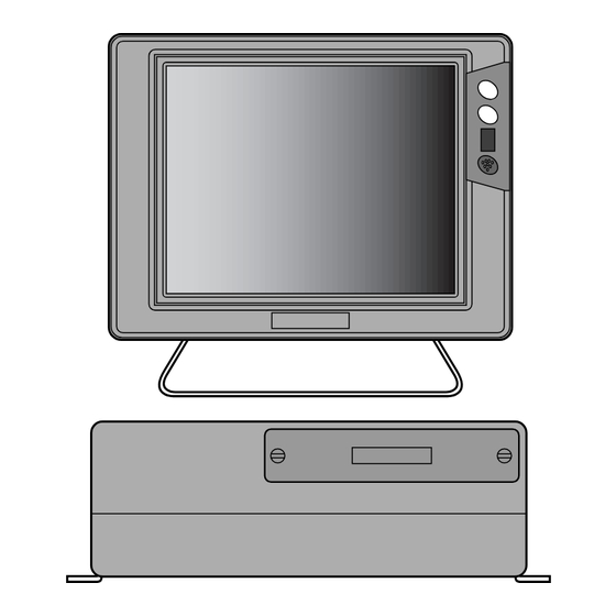
Page 88: Dimensional Drawing
DIMENSIONAL DRAWING ( ) is dimensions for HE-6801/HE-6802. 298 (256) -
Page 89: Wiring Diagram
WIRING DIAGRAM... -
Page 90: Connecting Diagram
CONNECTING DIAGRAM Connector for Input/Output It is used for connecting external GPS receiver or differential beacon receiver. NMEA0183 Start bit=1, Data bit=8 4800 bps (GGA GLL VTG) Parity bit=nil, Stop bit=1 Main Unit GPS Receiver Differential Beacon Receiver Data Output DC Power Supply Power Supply for... -
Page 91: Installation Of Main Unit And Display
INSTALLATION OF MAIN UNIT AND DISPLAY WARNING Do not install in a simple method. It causes to accident like human damage. Please install correctly according to [INSTALLATION OF MAIN UNIT AND DISPLAY]. Procedure of installing main unit Installation of main unit Install main unit into four holes of bracket with supplied screws referring to below figure. -
Page 92: Mounting The Gps Antenna
MOUNTING THE GPS ANTENNA DANGER Work on the boat is too unstable and risky. Mounting and maintenance of GPS antenna should be done after you land and fix the boat. Unless you keep it, human damage resulting in death or serious wound will occur. - Page 93 Connect extension cable with cable of GPS receiver or DGPS receiver. Wind joint with self-melt tape and then vinyl tape to prevent from coming water in. Turnable DGPS antenna stand Fix turnable antenna stand with four round pan-head tapping screws (M6X20, supplied). In case of using Screw Adapter GPS receiver or DGPS receiver has screw on it’s bottom (aluminum base).
- Page 94 Fix cable fastening with tie-wrap on the right figure to prevent from breaking cable caused from vibration. Connect extension cable with cable of GPS receiver or DGPS receiver. Wind joint with self-melt tape to prevent from coming water in. Method of mounting on mast Loose screw of cable Wind cable band around Fasten screw of clamp...
-
Page 95: Installation Of Transducer (Thru-Hull)
INSTALLATION OF TRANSDUCER DANGER Work on the board is too unstable and risky. Installation and maintenance of transducer should be done after you land and fix the boat. Unless you keep it, human damage resulting in death or serious wound will occur. WARNING Installation of the transducer or water temperature sensor inside the hull with adhesive should be done while you ventilate well inside the boat. -
Page 96: Installation Of Water Temp. Sensor
INSTALLATION OF WATER TEMP. SENSOR Water temperature sensor is option. DANGER Work on the boat is too unstable and risky. Installation and maintenance of the water temperature sensor should be done after you land and fix the boat. Unless you keep it, human damage resulting in death or serious wound will occur. When you work using electric tools, please keep your hands dry. -
Page 97: Standard Composition
STANDARD COMPOSITION Main Unit Display Bracket x 1pce. Clamping Knob x 2 pcs. Rubber Ring x 2 p cs. Washer x 2 pcs. Mush-room Tapping Screw for Main Unit Mush-room Tapping Screw for Display M6x20 SUSx 4 pcs. M5x20 SUSx 4 pcs. Remote (CR04) Power Supply Cable for Display (5P-5P 3m) Cable for Remote (4P-4P 3m) - Page 98 Transducer (Only HE-6801 & HE-6901) Brand Plate Map Card Operation Manual...
- Page 99 In case of HE-6801/HE-6901GP, HE-6802/HE-6902GP GPS Antenna Extension Cable Screw Adapter Turnable Antenna Stand (AD01) Round plane tapping screw x 4 Clamp Band Self-melted tape...
- Page 100 In case of HE-6801/HE-6901DGP, HE-6802/HE-6902DGP DGPS Antenna Extension Cable Screw Adapter Turnable Antenna Stand (AD01) Round plane tapping screw x 4 Clamp Band Self-melted tape...
-
Page 101: General Information Of Fish Finder
GENERAL IMFORATION OF FISH FINDER 1. THEORY OF FISH FINDER Theory of fish finder is same as echo. Ultrasonic pulses transmitted from the transducer into the water are reflected from fish school or the sea bottom and then they are received by transducer. Fish finder converts round-trip time between the time and the ultrasonic wave is transmitted and the time the reflected wave is received into distance and measures the depth It displays size or density of fish school, the outline of bottom or nature of bottom on the screen in... - Page 102 2. HOW TO DISTINGUISH THE FISH SCHOOL Important is comparison between display of fish school and catch It is possible to distinguish the fish sort by display of fish school to some extent. But even if fish sort is same, it’s form making school is different according to difference of fishing ground and difference of time (day and night, four seasons, variation of current).
-
Page 103: Trouble Shooting
TROUBLE SHOOTING When the condition of this unit is bad, please check the following points before asking to repair. Symptoms Causes Remedy Voltage of battery is lower than Power can not be turned on. Recharge the battery. standard value (11V). Contact of power connector is Tighten firmly. - Page 104 Symptoms Causes Remedy Bottom or fish can Contact of transducer connector Connect surely. Clean the surface of transducer and remove the rust, stain, is bad. not be displayed at etc. all. Replace in case of corrosion. Replace the transducer cable. Replace the connector of unit.
- Page 105 Symptoms Causes Remedy Many noise appear Decrease the sensitivity. Too high sensitivity. on the screen. Or set to Auto Gain (automatic sensitivity control). Noise disappears Interference with other boat’s adequate distance between own fish finder. boat and other keeps. Change the routing of cables such as Noise from engine.
-
Page 106: Specifications
SPECIFICATIONS...
Need help?
Do you have a question about the HE-6801 and is the answer not in the manual?
Questions and answers