Table of Contents
Advertisement
Quick Links
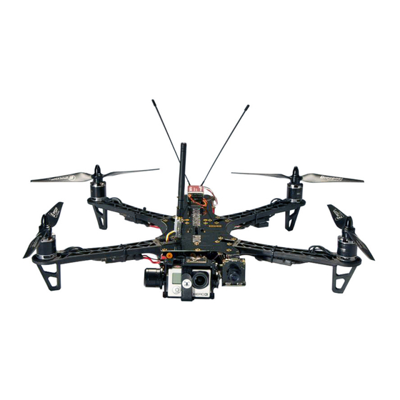
TBS DISCOVERY PRO Quadrotor
Durable and crash resistant multirotor perfect for
amateur and pro aerial videographers
Revision 2014-09-21
The TBS DISCOVERY PRO gimbal frame is the perfect tool for amateur and
pro aerial videographers. Sporting a fully stabilized, vibration isolated
camera gimbal it is the most powerful, compact, robust and versatile "take
anywhere" quadrocopter for filming available to date. All the wiring is
integrated into the frame, the copter is easy to build and outperforms
similar quads in terms of FPV range, flight time and video link quality.
By implementing the wiring into the frame, the copter is easy to build and outperforms similar quads in terms of
FPV range and video link quality. The DJI Flamewheel arms as predetermined breaking point protect your
electronics and are easily replaceable in the field.
Features
●
Integrated brushless gimbal & control board (plug & play!)
●
Built-in camera switch (GoPro live-out and pilot's camera)
●
Frame acts as power distribution board
●
Ready for long range FPV
●
TBS CORE (On Screen Display) with digital current sensor
●
Lightweight anodized CNC aluminum gimbal
●
Custom Gimbal IMU board
●
Tried and proven frame design - based on the world's most popular FPV quad!
●
Integrated brushless gimbal controller (BaseCam)
1
Advertisement
Table of Contents

Subscribe to Our Youtube Channel
Summary of Contents for TBS Discovery PRO Quadrotor
- Page 1 Revision 2014-09-21 The TBS DISCOVERY PRO gimbal frame is the perfect tool for amateur and pro aerial videographers. Sporting a fully stabilized, vibration isolated camera gimbal it is the most powerful, compact, robust and versatile "take anywhere"...
-
Page 2: Before We Begin
Before we begin Thank you for buying a TBS product! The TBS DISCOVERY PRO is a new multirotor aircraft from Team BlackSheep (TBS) for hobbyist, semi-pro and pro aerial videographers. It features the best design practices available on the market to date, providing great flying stability and incredible FPV characteristics. -
Page 3: Specifications
Specifications The following specifications are for the normal TBS DISCOVERY PRO. Long Range hardware will be different. Type: Asymmetric spider quadrotor Airframe: Reinforced black fiberglass (rear top RF transparent, bottom PDB) Battery: 4S (14.8V) 3300 to 4500mAh LiPo pack, max. 31 x 47 x 157mm... -
Page 4: Parts List
Parts list Before building your TBS DISCOVERY PRO, make sure the following items are included in your kit. 1x Bottom frame plate 1x Top frame plate 1x Gimbal IMU board 1x Pilot camera mount plate 1x GoPro link card 7x Red aluminum spacers 2x VTx and camera Molex 4x Black Molex 1.25 Picoblade... -
Page 5: Required Parts
Required parts To get in the air the following equipment and parts are needed for assembly. 4x DJI Flame Wheel arms 4x 400Hz Multirotor Speed 4x 900kV brushless motors (incl. Controller 18-30A prop adaptor and mounting screws) 4x 9x5 or 10x5-inch propellers 1x 4S 3300 to 4500mAh LiPo 1x Multicopter flight controller (2xCW, 2xCCW) - Page 6 Build guide The TBS DISCOVERY PRO comes in the usual quality finish and plug & play style the TBS DISCOVERY line is famous for. The essentials are fully integrated on the plates, to make the final assembly as easy as humanly possible.
-
Page 7: Frame Layout
Frame layout The TBS DISCOVER PRO frame is designed to reduce wiring and clutter. With simplicity in mind, we put all the electronics for the CORE, brushless camera gimbal and camera switching nicely integrated onto the top and bottom plates. All connections for the brushless gimbal motors, gimbal IMU and GoPro feed is plug&play. Calibrating the gimbal and configuring the CORE is made easily accessible via 4 push-buttons. - Page 8 Vibration free recordings The TBS DISCOVERY PRO is designed with a new vibration damping system where the gimbal rests on an array of 8+2 silicone mounts to form a push-pull compression system. This eliminates vibrations from propagating to the gimbal frame and HD camera.
- Page 9 Long range photography Team BlackSheep are the undisputed kings of long range FPV. With the TBS DISCOVERY PRO you can make camera shots that rival those of real helicopters. You can chase BMX drivers down an entire slope. You can film boats and yachts from the shore.
-
Page 10: Video Switching
Video switching Another great feature of the TBS DISCOVERY PRO is the ability to switch the video feed between the live FPV pilot camera and the gimbal camera. Fly through the FPV camera to line yourself up for a shot and then switch to the GoPro footage to position the camera (2-axis). - Page 11 Electronics installation 5V 12V Top frame rev. 10.2013 - by ivc.no/tbs (Optional) Gimbal Pitch Pitch motor Roll RC receiver Gimal Roll Gimbal Pitch Gimbal PPM IMU/GoPro Flight controller PPM Roll motor Camera switch Analog RSSI (For channel setup, refer to - + S the manufacurer’s manual) EzUHF RSSI Link...
-
Page 12: Choosing The Right Setup
Use these suggested setups as a “shopping list” if you are just getting started. Any existing gear you already own (e.g. remote controls, chargers, batteries) can be used with the TBS DISCOVERY PRO. These setups, with the exception of the Camera Tripod and the Remote Control, are available from Team BlackSheep. - Page 13 TBS DISCOVERY PRO setup for long range flights ● Expected flight time: 10-12 min ● Cost range: US$ 2’500 - US$ 3’000 Experience level: Expert ● Ideal for: Long, wide open fields, plains, coastlines and valleys or urban flying ●...
-
Page 14: Vibration Damping System
Camera gimbal assembly Start by assembling the brushless gimbal. There are a few steps which requires extra attention to detail in order to get the desired silky smooth operation of the gimbal. These are outlined in the following sections. Vibration damping system Start by inserting the damping balls on the mounting plate and frame brackets. - Page 15 ● On the main mounting plate, the cable for the motor will exit on the top notch and the plate needs to be oriented accordingly. Four of the top damping balls will face forward (toward the gimbal) holding the mounting bracket to the top frame, while the bottom four damping balls will point the opposite direction (backward) and hold the bottom end of the mounting bracket.
- Page 16 ● Use a short length of a servo-wire or a piece of string to more easily feed the damping balls through the 16 holes on the base mounting plate and frame mounting brackets. Wrap the wire or string inside the groove of the balls, one or two turns, feed both ends into the hole, and pull through using a plier. ●...
- Page 17 Gimbal assembly The gimbal screws use 1.5mm (M2), 2.0mm (M2.5) and 2.5mm (M3) hex screwdrivers. Keep the screws loose at the start and fully tighten them at the end of the assembly, this makes it easier to align all the parts. For a good secure fit, use a very small amount of light/medium strength threadlock on all metal-to-metal-screws.
- Page 18 Note: Parts with the same number belong to the same group. Gimbal assembly diagram rev. 01. 2014 - by ivc.no/tbs (1) M3x4mm motor mount screws (4) M2.5x5mm frame screws (2) M2.5x6mm gimbal screws (4) M2x6mm grub screws (3) M2x12mm bearing clamp screw (5) M3x6mm lever-to-motor mount screws...
- Page 19 To minimize cable tension and friction, feed the 5-pin Molex connector through the bearing and slide ● the bearing over the flange on the left side of the gimbal cage (completed previously). Align the shrink tube pieces in such a fashion that there is no shrink tube on the inside corner of the ●...
- Page 20 Continue by attaching the main damping mounting plate (completed previously) and back lever arm to ● the rear/roll motor. Align the cable with the notch in the mounting plate and secure it using 4x M3x6mm screws. Feed the remaining cables through the two oval holes on either side of the plate. Make sure the cables does not obstruct free movement or is under tension.
- Page 21 Post frame assembly ● Continue assembling the rest of the DISCOVERY PRO frame and at the end of the build, slide in the gimbal assembly, plug in the 3 cables for pitch, roll and IMU to the designated location and secure the gimbal using 6x M2.5x5mm frame (arm) screws.
- Page 22 If the lever arm touches the flight controller when installed, either move the controller slightly or ● remove the spacer and two screws (these are not absolutely necessary). Finally, feed the GoPro gimbal velcro strap through the slots on the bottom cage mounting plate. ●...
-
Page 23: Frame Assembly
Frame assembly The following sections will show you the essential steps to assembling the base of the frame and connect the electronics to the frame. In addition to the following assembly instructions, we have produced a both a summarized “How To”... - Page 24 (3) Pin header (1) M3x6.5mm spacer screws (2) M2.5x5mm frame arm and gimbal screws (7) Aluminium spacers (4) Top plate (6) Frame arm (5) Bottom plate DRAWN TBS Associates Inc 31.07.2013 Parts with the same number CHECKED belong to the same type. TITLE APPROVED SIZE...
- Page 25 Spacers ● Next, add the red spacers (posts) to the bottom frame plate using the supplied M3x6.5mm hex screws. Add a small drop of threadlock to help secure the frame. It is recommended to only apply on the bottom screws for easy repairs/maintenance. There are three spacer positions in the battery compartment to make it easy to balance (CG) the frame.
- Page 26 One important note for ESCs that do not carry the “OPTO” label or are not TBS BULLETPROOF designs, ● is that only one of the four ESCs should provide 5V BEC power to the flight controller. The middle red wire on the end connector should be disconnected on three of the ESCs. If the flight controller is providing power (e.g.
-
Page 27: Flight Controller
Flight controller ● Decide whether you want to use traditional PWM or PPM/S.BUS control signal mode. The frame is laid out to work with both types of setups. As of writing, TBS suggests the DJI NAZA-M flight controller in PPM/S.BUS mode (together with a compatible receiver) and an optional GPS add-on (for return-to-home capability) for a clean wiring layout and great out-of-the-box experience. - Page 28 ● (DJI NAZA only) To save weight and space, the PMU (V2) can be disconnected and removed after the final configuration has been made. Although, 5V power still has to be provided from at least one of the ESCs. Start out using the following suggested gains for NAZA-M Autopilot and tune accordingly . Setup ...
- Page 29 Feed the battery straps through the two slots in the battery compartment. Only one strap is really ● necessary to provide adequate friction to keep the battery fastened. Optional: Use different colored frame arms for the front and back pair to make it easier to identify the orientation of the quadcopter in the air.
- Page 30 ● Plug in the bullet-connectors to the speed controllers. Swap any two wires to change the direction of rotation if they do not rotate as shown below. See the image above for the most commonly used motor setup (e.g. NAZA-M.)
-
Page 31: Top Plate
Top plate R/C control signal headers ● To get a clean R/C receiver-to-flight controller wiring, it is recommended to use the header on the top plate. There are 8 traces to support up to equally many PWM (Pulse Width Modulation) channels. When using a PPM (Pulse Position Modulation) compatible receiver and flight controller, only one trace (Channel 1) is used. - Page 32 The channels with a text label, i.e. PPM, GIMBAL_ROLL, GIMBAL_PITCH, CAM_SWITCH and ● RSSI_ANALOG, has the signal pin (∏) hardwired directly to their respective electronics section on the top frame (i.e. flight controller PPM break-out, gimbal controller roll/tilt, camera switcher, and CORE RSSI signal).
- Page 33 TBS DISCOVERY PRO - Common receiver and ight controller setups EzUHF - NAZA - PPM - RSSI Link EzUHF - APM2 - PPM - RSSI Link R/C receiver Flight controller R/C receiver Flight controller - PPM: Use a jumper over the - Con gure “Muxed PPM”...
- Page 34 (EzUHF Rx 8ch only) The CORE can decode the digital RSSI signal from the receiver via the separate ● “OSD Link” port and display RSSI on each of the two antennas and overall signal quality (including packet loss) of the R/C uplink. A 5-pin Molex cable is included which plugs into the EZUHF_RSSI_LINK connector on the top plate.
- Page 35 Attach the the 9-pin plate-to-plate bottom link cable to the designated connector on the bottom plate. ● It carries carries current sensor signal, Vbatt, ground, +V5, +V12 up and PPM down. When closing the frame, plug in the cable to the corresponding connector on the top plate.
- Page 36 FPV and gimbal gear The FPV gear is designed to be installed on the front section of the frame to achieve as much separation between the R/C- and FPV-radio environment as possible. Keep in mind that the former is listening while the latter is broadcasting.
- Page 37 CORE menu layout Button Enter ...
- Page 38 The solder pads next to the sockets can be used to connect your gear, but try to connect your FPV ● camera and video transmitter via the Molex connectors on the board. With that, you will not risk ripping off the pads from the frame when pulling too heavy on a cable. Modify our cable harness when using other than TBS suggested gear.
- Page 39 Decide whether you can use the supplied wires and connector socket on the top frame or connect the ● camera and video transmitter via the round solder pads. The supplied picoblade Molex cable “5V VTx” are designed to work with the TBS GREENHORN, TBS ROOKIE, Lawmate video transmitters, and the supplied “12V CAM”...
-
Page 40: Video Transmitter
Video transmitter ● Put the video transmitter close to the front on the top plate. Use zip-ties and/or self-adhesive foam pads to fit the transmitter. TBS offers a custom made mounting bracket for easy vertical install over the front-right frame arm. To avoid possible video interference, be sure to use a foam or gel pad between the frame and VTx unit to reduce exposure to vibration. - Page 41 TBS DISCOVERY / DISCOVERY PRO - Video transmitter (VTx) setups rev. Feb 2014 - by ivc.no/tbs TBS/Lawmate VTx Boscam VTx · 1.2G 500mW · 2.4G 500mW · 2.4G 100mW, 200mW, 500mW · 5.8G 200mW, 400mW, 500mW · 5.8G 25mW (TBS Greenhorn), 200mW (TBS Rookie), 500mW (TBS Boss) Supply voltage: 5.0-5.5V (all) Supply voltage: 12-14V (3S) Supply voltage: 12-14V (3S)
- Page 42 Brushless gimbal controller Plug in the 3 Molex cables for the pitch- and roll-motors, as well as the IMU board, into the connectors ● labeled “PITCH”, “ROLL”, and “IMU” located near the front on the top plate. ● The controller comes pre-configured with PID gains which are fine-tuned for use with a GoPro HD Hero3 and no additional accessories (lens protection or housing.) Tuning may be necessary (PID, power) when using an older GoPro model or different add-ons.
- Page 43 ● If the camera gimbal is not level at start-up, move the gimbal and quad to a perfectly level position (use a bubble leveler) and press the “GIMBAL CAL.” button on the top plate for 3-5 seconds until the gimbal motors release. Wait for the blue LED to stop blinking and motors to lock again. Ensure that the gimbal is perfectly still and straight during this calibration process.
- Page 44 GoPro link ● With video switching now possible on the DISCOVERY PRO, the kit includes a small adaptor which plugs into the GoPro 30-pin bus connector to provide video output and the possibility to charge the GoPro while in flight. The charging is disabled by default and it is only recommended to enable the “500mA/1A”...
- Page 45 ● The OSD is enabled by default, to disable it completely hook up video and press the “ENTR” button on the top plate for 4-5 seconds, toggle to the “OSD" menu and select "OSD OFF". ● In the picture above the video feed is switched to the GoPro camera. Notice how the OSD adapts to the GoPro margins.
- Page 46 Brushless gimbal stabilization Integrated gimbal controller Setting up a gimbal the right way can be a daunting task, fortunately we licensed the SimpleBGC firmware (AlexMos) and the SimpleBGC hardware layout from Viacopter. The controller has all the parameters pre-set and gains tuned by TBS for a great out-of-the-box experience. The gimbal controller is fully embedded into the frame (a world's first), no soldering or software configuration required.
- Page 47 The GoPro HD Hero camera is the most commonly used HD recording camera (as of writing) for sport purposes, thanks to its wonderful high-quality picture and compact size. The TBS DISCOVERY PRO was designed around the GoPro to take advantage of its great features.
- Page 48 Center of Gravity optimization A properly balanced multirotor will distributing the weight (mass) equally over the four motors. The ● mark on the bottom plate is the Center of Thrust (CT, CoT) mark and the Center of Gravity (CG, CoG) spot is 15mm forward of this mark.
- Page 49 Center of Gravity diagram rev. 08. 2013 - by ivc.no/tbs...
- Page 50 Dual-pilot support (ADVANCED USERS ONLY!) Split dual-pilot support is possible in situations where a separate operator for piloting the quad and camera is preferred. Extra equipment is needed for the extra video link and R/C control uplink (2-axis gimbal and yaw adjustments.) Installation of the video transmitter and R/C receiver follows the same basic setup principles described previously.
- Page 51 Dual operator - Introducing a separate video operator for the gimbal roll and tilt control requires ● one additional video transmitter and R/C receiver. Disable the video switcher, cut the trace between the two “GP OUT SEL” jumper pads and solder the left pad to the middle. ●...
- Page 52 TBS CORE PNP PRO installation The TBS CORE PNP PRO upgrade will make the DISCO PRO a full-featured quadcopter. You will be able to see current power index, home direction, speed, altitude, distance to home, exact GPS coordinates and notifications to assist you while flying.
- Page 53 TBS CORE PNP PRO installation diagram for TBS DISCOVERY PRO Sept. 2014 - by ivc.no/tbs GPS module (optional) TBS CORE PNP PRO unit ENTER LINK Note: no power or audio lead (available separately) RSSI B-PWR TBS CORE PNP PRO Caution: do not use the normal CAM-cable to...
-
Page 54: First Flight
Flight First flight Check that the flight battery and transmitter battery is fully charged. Make sure all the screws on the frame and the propellers are spinning the correct direction and secured, and that the battery strapped down. Balance the quadcopter around the Center of Gravity (CG) spot by repositioning the battery. -
Page 55: Good Practices
Good practices We have compiled a list of all of the things that have been tried and tested in countless environments and situations by TBS crew and other experienced FPV pilots. Follow these simple rules, even if rumors on the internet suggest otherwise, and you will have success in FPV. ●... - Page 56 Try to achieve as much separation of the VTx and R/C receiver as possible to lower the RF noise floor ● and EMI interference. ● Do not buy the cheapest equipment unless it is proven to work reliably (e.g. parts falling off, multitudes of bug fix firmware updates, community hacks and mods are a good indicator of poor quality and something you do NOT want to buy for a safe system).
-
Page 57: Troubleshooting
Troubleshooting ● Issue: Horizontal lines in pilot video downlink Solution: If there are lines in the video during flight that disappear as soon as you land, your video transmitter is exposed to too much vibrations. Memory foam in conjunction with the Flame Wheel VTx mount will take out the vibrations in an instant and give you crystal-clear video. - Page 58 ● Issue: Gimbal controller displays a blue light and motors not engaging Solution: Try to connect your PRO to the SimpleBGC UI software and check what message you get there. There is possibly a bad connection between the top plate and the gimbal IMU. Check the connection by verifying the voltage at the IMU when everything is plugged in: ●...
-
Page 59: Recommended Parts
Recommended parts Below is a list of compatible R/C and FPV gear for the TBS DISCOVERY PRO quadrotor. This will hopefully make it easier to pick up spare parts and upgrades. Power sets TBS 900kV2 Motor / ESC Combo For the more sophisticated, agile-flight loving pilot or for those requiring super-vibration-resistant and high quality motors. - Page 60 Propellers ● Graupner E-Prop 9x5-inch propellers ● Graupner E-Prop 10x5-inch propellers GemFan E-Propeller 10x5 Carbon Fiber propellers ● RCTimer Carbon Fiber 9x5-inch propellers ● RCTimer Carbon Fiber 10x5-inch propellers ● Battery ● TBS 4S 3300mAh 30C or KyPOM KT4500/35-4S Lipo pack ●...
-
Page 61: Spare Parts
Spare parts You can either get spare parts directly from us (team-blacksheep.com) or from one of our distributors and retailers near you. Our ever-growing list of retailers is published on the left at team-blacksheep.com/shop. - Page 62 Appendix ● Frame assembly diagram ● Gimbal assembly diagram ● Electronics installation diagram Common R/C receiver setups ● Video transmitter installation diagram ● CORE menu layout ● ● Center of Gravity diagram Manual written and designed by ivc.no in cooperation with TBS.
Need help?
Do you have a question about the Quadrotor and is the answer not in the manual?
Questions and answers