Advertisement
HS-2510W/HS-2512W
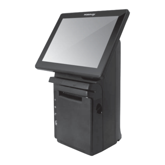
JIVA Desktop POS
User Manual
Product Features
Standard Features
System
Intel Bay Trail-D J1900 2.0G CPU up to 2.42G, 2M Cache,
quad-core Celeron CPU
DDR3L 1333 FSB, SO-DIMM socket *1, Max 8G
Mechanical Structure
Fan free structure for harsh environment
Monitor tilt adjustment angle from 17° to 45°
Display
9.7"/12" LCD touch panel, 1024x768 resolution
P-CAP touch panel
15590901010 Ver. Original
http://www.posiflex.com
Package Contents
HS-251xW desktop POS x 1
Power adaptor x 1
Power cord x 1
Desktop mounting kit pack x 1
(including 4 fixing screws, 4
plastic anchors, and 1 desktop
mounting bracket)
Desktop POS user manual x 1
Recovery or information CD x 1
Optional item(s)
1
Advertisement
Table of Contents

Related Manuals for POSIFLEX HS-2510W

Summary of Contents for POSIFLEX HS-2510W
-
Page 1: Package Contents
HS-2510W/HS-2512W JIVA Desktop POS User Manual Package Contents HS-251xW desktop POS x 1 Power adaptor x 1 Power cord x 1 Desktop mounting kit pack x 1 (including 4 fixing screws, 4 plastic anchors, and 1 desktop mounting bracket) Desktop POS user manual x 1... - Page 2 Optional Items System SSD storage device DDR3L 1333 FSB, SO-DIMM socket *1, Max 8G Windows XP, POSReady 7, Windows 7, Windows Embedded 8.1 Industry, Android per request WIFI Wireless LAN Views of the HS-251xW Front View of HS-251xW LCD Touch Panel 3-track Smart Card Reader Magnetic Stripe Reader...
- Page 3 Left Side View of HS-251xW Power Button Bottom View of HS-251xW Bottom IO Interface View of I/O Interface of HS-251wX Top I/O Interface COM (DB9) Port DB25 parallel port USB3.0 Port VGA Port...
- Page 4 Bottom I/O Interface 12VDC-IN Power Jack RJ11 Cash Drawer Port USB2.0 Port RJ45 LAN Port COM Port PS2 Port for Keyboard Line-Out Jack Connecting Power Adapter and I/O Cables Follow the steps listed below to open the bottom I/O-port protective cover and connect cables. Make the desktop POS lie on the surface of a desk and the LCD touch panel face down.
- Page 5 Connect power adapter and I/O cables to the bottom I/O interface of the desktop POS. Make the cover join to the wedge portions of the rear plate of the POS. Determine that the cover is well wedged to the wedge portions of the rear plate of the POS.
- Page 6 Determine that the I/O Cable out interface is covered and the cable passes through the cable exit. Connect I/O cables to the top I/O interface If you want to connect I/O cable to the top I/O interface, follow the steps listed below to open the top I/O-port protective cover and connect I/O cables to the top I/O interface.
- Page 7 Connect I/O cables to the top I/O interface of the desktop POS and then gather the Cable cables together in the cable Exit exit. Break the cable-exit cover. Make the cover join to the wedge portions of the rear plate of the POS. Determine that the cover is well wedged to the wedge portions of the rear plate of...
- Page 8 Determine that the I/O interface is covered and the Cable out cable passes through the cable exit. Mounting the POS onto a Table To avoid the POS from backward tilting and wagging when a user touches the LCD panel, use the desktop mounting kit shipped with the POS to hold and secure the POS firmly on a table.
- Page 9 Push hard the POS backward along the 2 tracks of the bracket on the table to firmly secure the POS. To completely mount the desktop POS onto the table, you can apply two more self-taping screws into the 2 holes formed on the base stand of the POS, as illustrated below.
-
Page 10: Status Led Indicator
Operating System Recovery For the HS-251xW main system preloaded with an operating system on HDD, Posiflex provides a recovery CD shipped with the main system for the preloaded operating system. The system integrator shall take care of software restoration after the OS is recovered. -
Page 11: Loading Paper
A and B at the angle from 17° to 45°. Optional Upgrade Kits Posiflex HS-251xW can work with multiple optional upgrade kits, such as MSR, Smart Card Reader and the like. For the detailed instruction, refer to the technical manual of HS-251xW or each of... -
Page 12: Specifications
9.7" 1024 x 768 LCD P-CAP 12" 1024 x 768 LCD P-CAP Display touch panel touch panel D-SUB 15 Pin, with 12V power for Posiflex LCD Monitor Interface Two SATA ports for 2.5'' or 1'' SATA device; EMMC adaptor Storage Board 8G/16G/32G on M/B... - Page 13 0°C - 40°C, 20%RH - 90%RH (Equipped with HDD); Condition 0°C - 50°C, 20%RH - 90%RH (Equipped with SSD) Storage -20°C - 70°C, 10%RH - 90%RH Condition To get the detailed information on HS-251xW, please download the technical manual of this model from Posiflex Global Website (http://www.posiflex.com/en-global/Download/download).
- Page 14 <MEMO>...
Need help?
Do you have a question about the HS-2510W and is the answer not in the manual?
Questions and answers