Table of Contents
Advertisement
ALINCO, INC.
Yodoyabashi Dai-bldg 13F
4-4-9 Koraibashi, Chuo-ku, Osaka 541-0043 Japan
Phone: +81-6-7636-2362 Fax: +81-6-6208-3802
http://www.alinco.com
E-mail:export@alinco.co.jp
VHF FM Transceiver / 136.000-173.995MHz
All EU and EFTA member states. Operator
license is required.
Copyright Alinco, lnc. PS0663/FNEG-EN
Printed in China
Advertisement
Table of Contents

Related Manuals for Alinco DJ-100


Summary of Contents for Alinco DJ-100
- Page 1 ALINCO, INC. Yodoyabashi Dai-bldg 13F 4-4-9 Koraibashi, Chuo-ku, Osaka 541-0043 Japan Phone: +81-6-7636-2362 Fax: +81-6-6208-3802 http://www.alinco.com E-mail:export@alinco.co.jp VHF FM Transceiver / 136.000-173.995MHz All EU and EFTA member states. Operator license is required. Copyright Alinco, lnc. PS0663/FNEG-EN Printed in China...
-
Page 2: Instruction Manual
VHF FM Transceiver DJ-100 Instruction Manual Thank you for purchasing your new Alinco transceiver. Please read this manual carefully before using the product to ensure full performance, and keep this manual for future reference as it contains information on after-sales service. -
Page 3: Before Transmitting
Introduction Thank you very much for purchasing this excellent Alinco transceiver. Our products are ranked among the finest in the world. This radio has been manufactured with state of the art technology and it has been tested carefully at our factory. It is designed to operate to your satisfaction for many years under normal use. - Page 4 Alinco accessories and the radio has not been disassembled by the customer. The factory has tested and made the equipment compatible to IP54 certification during engineering.
- Page 5 Features ■ Output power selectable 5W/2W/0.5W ■ 200 PC-programmable channels ■ Li-Ion battery pack and stand-charger as standard accessories ■ Alphanumeric name tags ■ FM broadcast 76-108MHz receiver built-in ■ Selectable Battery-save parameters ■ Busy Channel Lockout ■ Voice Compander (Reduce Noise & enhance audio clarity) ■...
-
Page 6: Safety Training Information
DO NOT operate the transceiver without a proper antenna attached, as it may damage the transceiver and may also cause you to exceed FCC RF exposure limits. A proper antenna is the genuine antenna supplied with this transceiver by Alinco or ones specifically authorized by the antenna manufacturer for use with this transceiver. - Page 7 • Use only the genuine Alinco accessories listed in this instruction manual for RF safety. Third party accessories are not guaranteed for RF safety by Alinco. The above provides the information needed to make users of this transceiver aware of RF exposure, and what to do to assure that this transceiver operates with the FCC RF exposure limits.
-
Page 8: Fcc Information
FCC INFORMATION FOR CLASS B UNINTENTIONAL RADIATORS: This equipment has been tested and found to comply with the limits for a Class B digital device, pursuant to part 15 of the FCC Rules. These limits are designed to provide reasonable protection against harmful interference in a residential installation. -
Page 9: Environment And Condition Of Use
Alert Environment and condition of use It is recommended that you check local traffic regulations regarding the use of a radio equipment while driving. Some countries prohibit or apply restrictions for the operation of radios and mobile- phones while driving. Do not use this product in close proximity to other electronic devices, especially medical ones. -
Page 10: Handling This Product
The manufacturer declines any responsibilities against loss of life and property due to a failure of this product when used with or as a part of a device made by third parties. Use of third party accessory may result in damage to this product. It will void our warranty for repair. Handling this product Be sure to reduce the audio output level to minimum before using an earphone or a headset. -
Page 11: In Case Of Emergency
Securely plug the adapter into the wall outlet. Insecure installation may result in short-circuit, electronic shock and/or fire. Do not use the adapter if the plug or socket contacts are dirty. Overheating and/or short-circuiting may result in fire, electric shock and/or damage to the product. In case of emergency In case of the following situation(s), please turn off the product, switch off the source of power, then remove or unplug the power-cord. -
Page 12: About Transceiver
Alert Environment and condition of use Do not use the product in proximity to a TV or a radio. It may cause interference or receive interference. Do not install in a humid, dusty or insufficiently ventilated place. It may result in electric shock, fire and/or malfunction. - Page 13 Use a clean, dry cloth to wipe off dirt and condensation from the surface of the product. Never use thinner or benzene for cleaning. Check with your local waste officials for details on recycling or proper disposal in your area. PC PROGRAMMING NOTE: The utility software may be available to distributors/dealers only.
-
Page 14: Table Of Contents
TABLE OF CONTENTS STANDARD ACCESSORIES ............................01 Standard Accessories ..............................01 KEY OPERATIONS / QUICK CHART ...........................02 BATTERY INFORMATION .............................03 Charging Operation..............................03 Battery Charger Type..............................03 Notice for Charging Battery ............................03 How to Charge the battery pack ..........................05 How to Store the Battery ............................07 Installing / Removing the Li-ion Battery ........................07 Installing / Removing the Antenna ..........................08 Installing / Removing the Belt Clip ..........................08... - Page 15 TABLE OF CONTENTS Transmitting................................16 [PF1] Key Function ..............................16 Side [PF2] Key Function ............................17 Switching between VFO and Memory Mode ......................17 ADVANCED OPERATIONS ............................18 Channel Edit ................................18 Delete Channel ................................18 FM Radior Receiver ..............................18 Add or Cancel DTMF, 2TONE, 5TONE, FSK Signaling .....................19 CTCSS / DCS Scan ..............................20 Add or cancel CTCSS/DCS ............................21 Frequency Scan, Channel Scan or FM Search ......................21...
- Page 16 TABLE OF CONTENTS Choose To Transmit 2TONE ............................29 Choose To Transmit 5TONE ............................30 Choose To Transmit FSK ............................30 Signaling Combination ..............................31 Frequency Step .................................32 Offset Direction ................................32 Offset Frequency ................................33 Wide/ Narrow FM Mode .............................33 Frequency Reverse ..............................34 Talk Around ................................34 Busy Channel Lockout ...............................35 Prohibits transmitting ..............................35 Sub Channel Display Setup ............................36...
- Page 17 TABLE OF CONTENTS Display Mode ................................45 DTMF Self ID display ..............................45 5TONE Self ID Inquiry ..............................46 Tone-burst tone setting ..............................46 Battery Save Ratio ..............................47 FM Radio ..................................48 Password ...................................48 Reset ..................................49 DEFAULT SETTINGS ..............................50 OPTIONAL ACCESSORIES ............................51 RECOMMENDED INSTALLATION OF EARPHONE MICROPHONE................52 AUXILIARY FUNCTIONS ..............................53 Cable Cloning................................53 Communication Note..............................53...
-
Page 18: Standard Accessories
STANDARD ACCESSORIES Standard Accessories Antenna Battery Charger AC Adaptor (A shape may vary) Belt Clip Instruction Hand Strap Manual NOTE: Accessories may differ depending on the version you have purchased. Please contact your local dealer for details of standard accessories and the warranty-policy before purchase. Professional FM Transceiver... -
Page 19: Key Operations / Quick Chart
KEY OPERATIONS / QUICK CHART Function Key Operation Parameter Instruction Page 【 1 】 【 A 】 FM radio On/Off Activate FM Broadcasting Receiver Choose DTMF、2TONE、5TONE、FSK as 【 A 】 【 2 】 Add/delete Optional Signaling optional signaling of current channel Scan CTCSS when channel set CTCSS 【... -
Page 20: Battery Information
Battery Charger Type Please use Alinco's designated charger, other models may cause explosion. After installing the battery, when the radio displays low battery, please charge the battery. - Page 21 BATTERY INFORMATION Caution • Risk of explosion, generation of heat or leak of chemicals inside if the battery is replaced by an incorrect type or reverse polarity. Use always the recommended types of batteries in this manual only. • The battery pack isn't fully charged when shipped. It must be charged before use. •...
-
Page 22: How To Charge The Battery Pack
BATTERY INFORMATION How to Charge the battery pack 1.Plug the AC adaptor into the AC outlet, then plug into the DC jack ,the indicator lights orange for 1 second and goes out---waits to charge. 2.Slide the battery or transceiver with battery into the charger;... - Page 23 BATTERY INFORMATION 6. LED Indicator: self-examine Charge Fully STATUS (No battery) Pre-charging Trouble when power on normally Charged Orange Red blinks for 5 Red blinks None Green (for 1 second) minutes alternatively NOTE: ▲ Trouble means battery heating, short-circuit or charger malfunction. Remove the battery pack from the charger immediately and contact to your local dealer for services.
-
Page 24: How To Store The Battery
INSTALLATION & CONNECTION How to Store the Battery WARNING Do notshort-circuit battery terminals. 1.The battery should be kept in the status Never attempt to remove the casing from the battery of 50% discharge when storing. pack. 2.It should be kept in cool, dry environment Never assemble the battery hazardous in explosive and remove it from the transceiver. -
Page 25: Installing / Removing The Antenna
INSTALLATION & CONNECTION Installing / Removing the Antenna Installing the Antenna: 1. Hold the antenna by its base. 2. Align the grooves at the base of the antenna with the protrusions on the antenna connector. 3. Slide the antenna down and turn it clockwise until it stops. 4. -
Page 26: Accessories
INSTALLATION & CONNECTION Accessories Remove the jack cover and insert the accessory plug into the jack,as shown. When the accessory is not used, please be sure to put on cover with securely. NOTE: 1.To keep the radio dust and splash resistant, the cover must be closed properly with the original supplied cover. -
Page 27: Getting Acquainted
GETTING ACQUAINTED LCD Display Please refer the chart below to understand the meanings of icons that appear on the LCD display. Frequency Reverse Priority Scan Offset direction VOX Function Scan Skip Talk Around Narrow band Scramble (Encryption) CTCSS FUNC Icon Battery Capacity Function Menu Serial No. -
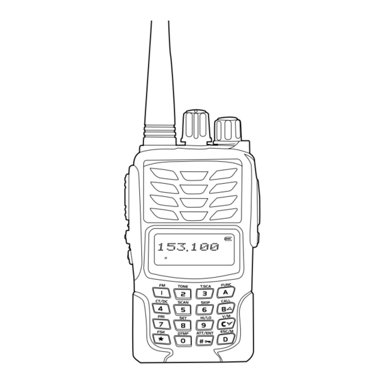
Page 28: Front Panel
GETTING ACQUAINTED Front Panel Main dial Antenna Power / Volume Switch TX/RX indicator, RX is Green, TX is Red Speaker Microphone A key/Function key B key/Up key/Call key C key/Down key/V/M Numeric keys D key, Exit key or channel/ VFO Exchange key Professional FM Transceiver... -
Page 29: Side Panel
GETTING ACQUAINTED Side Panel Accessory and PC PTT key programming port PF1 key (1 Primary Function key) PF2 key (2 Primary Function key) Belt Clip Battery Left Panel Right Panel Professional FM Transceiver... -
Page 30: Basic Operations
BASIC OPERATIONS Power On and off Turn 【 POWER 】 / 【 VOLUME 】 dial clockwise to power on. Turn it counterclockwise to power off. Adjusting Audio output level Press and hold [PF2] key to monitor white noise to refer to the current audio level. -
Page 31: Frequency Input By Keypad
BASIC OPERATIONS Frequency Input by Keypad In VFO mode or FM radio receiver, You may directly enter frequency through numeric keys. 1.Press to switch to VFO. 2.Enter the desired frequency in 6-digit by numeric keys. Example: To enter 155.125, press [1][5][5][1][2][5]. By pressing the last [5], a dot appears after the MHz unit and the radio is ready to operate. -
Page 32: Change Frequency / Channel Through Main Dial
BASIC OPERATIONS Change Frequency / Channel Through Main Dial Under frequency mode, you can change the current frequency to desired one through main dial; turn clockwise to increase frequency; counter-clockwise turn to decrease, every click will increase/decrease one step. ● This transceiver has 9 step size: 5, 6.25, 8.33, 10, 12.5, 20, 25, 30 and 50 KHz, channel steps. -
Page 33: Receiving
BASIC OPERATIONS 2. Squelch Off: press [PF2] key to hear the background noise, press [PF2] again to return to normal operation. Note: The above functions should be set in software. Manual setting is not available. ● Receiving Select the operating mode and frequency or channel that you wish to operate. When a signal is received on the frequency that you selected, and S-meter is displayed on the LCD, then the received signal can be heard. -
Page 34: Side [Pf2] Key Function
BASIC OPERATIONS 2.In receiving mode, press and hold to alarm.(you can shut off this function by software) 3.In transmitting mode, press to transmitting selected Tone-pulse signaling. 4.Press this key to power on transceiver, and get into wire cloning mode. Side Key [PF2] Function Monitor function (squelch off or momentary off per preprogramming). -
Page 35: Advanced Operations
ADVANSED OPERATIONS Note: Most part of this ADVANSED OPERATION chapter is useless for preprogrammed radio users. ● Channel Edit 1.In main channel frequency mode or sub-channel frequency mode, enter the frequency and signaling as desired, after pressing key, the top left corner of LCD displays " ", then press , the channel number twinkling means getting into store/ delete channel mode. -
Page 36: Add Or Cancel Dtmf, 2Tone, 5Tone,Fsk Signaling
ADVANSED OPERATIONS 3. When FM radio is on, press key firstly, then press key to search broadcasting stations, the searched stations will be saved into FM radio channels automatically. 4. When FM radio is on, press key firstly, then press key to scan broadcasting stations, when meeting stations, scan will stay 5 seconds then resume. -
Page 37: Ctcss / Dcs Scan
ADVANSED OPERATIONS 4. When the first digit displays "M", it has FSK signaling squelch when receive. Hold [PTT] key then press [PF2] key to transmit the prestored and selected FSK signaling. 5.When displays none of alphabetical character, DTMF, 2TONE, 5TONE, FSK signaling are cancelled. -
Page 38: Add Or Cancel Ctcss/Dcs
ADVANSED OPERATIONS Add or cancel CTCSS/DCS Under standby state, press key, the top left corner of LCD displays " " icon, then press key to choose CTCSS/DCS signaling. 1. LCD displays "CT" icon, means current channel add CTCSS encode and decode. -
Page 39: Scan Channel Skip
ADVANSED OPERATIONS 2.Channel Scan In channel mode, it scans in accordance with preprogrammed channels. Press any key except keys to stop scanning. 3.FM Search In FM broadcast receiver mode, it scans in accordance with 100KHz step. Press any key except keys to stop scanning. -
Page 40: Priority Monitor
ADVANSED OPERATIONS Priority Monitor In VFO mode, after pressing key, while icon is displayed on the top left corner, press key to activate the priority monitor. PRI icon appears and monitors preprogrammed priority channel once every 5 seconds. When the priority channel receives a matching signal, it will stay tuned to the priority channel until current signal disappears. -
Page 41: Fsk Message Single Transmitting
ADVANSED OPERATIONS FSK Message Single Transmitting 1. In standby state, press key, the top left corner of LCD displays " " icon. 2. Press key, LCD displays '_MSG_'. 3. Turn main dial to select the desired character. 4. Press [PF1] key to confirm the current character and enter next character . 5. -
Page 42: Fsk Message All Transmitting
ADVANSED OPERATIONS 8. Press [PTT] key to transmit FSK message. FSK Message All Transmitting 1. In standby state, press key, the top left corner of LCD displays " " icon. 2. Press key, LCD displays '_MSG_'. 3. Turn main dial to select the desired character. 4. -
Page 43: Dtmf Code Searching And Setup
ADVANSED OPERATIONS DTMF Code Searching And Setup After pressing key, the top left corner of LCD displays" " then press 0 key, it displays the current DTMF group. (16 groups in total) 1.Turn main dial to select the desired group and DTMF data, and press PTT to transmit the desired DTMF data. -
Page 44: Remotely Stun /Waken
ADVANSED OPERATIONS To wake up (revive) the radios again, send the KILL code with # at the end. Example: If 1234 is the KILL code, send 1234# to revive. It displays "WAKEN" when revive code is received. Turn off and turn on to operate. Remotely Stun /Waken By transmitting preprogrammed STUN code, the radios that received the code will become temporary out-of-service except for receiving. -
Page 45: Channel Operations
CHANNEL OPERATIONS For VFO or Memory channel mode users, temporary changes in preset channel parameter may be available. Such temporary changes won't be held in the memory and will be deleted when a channel is changed or turn off the radio. This feature is not available to dealer-programmed Channel mode users. -
Page 46: Ctcss/Dcs Decode
CHANNEL OPERATIONS CTCSS/DCS Decode By using this function with CTCSS/DCS encode feature, you hear only signals that are sent with matching tones. (Such operations are often reffered to as Tone-Squelch or DCS squelch) 1.After pressing key, the top left corner of LCD displays" "... -
Page 47: Choose To Transmit 5Tone
CHANNEL OPERATIONS Choose To Transmit 5TONE By preprogramming the 2-Tone setting in advance, you may select the tone and transmit it. 1.After pressing key, the top left corner of LCD displays" " then press key. 2.Press key to choose menu 04. LCD will display " 5TONE " 3.Turn main dial to choose the desired 5-Tone signal. -
Page 48: Signaling Combination
CHANNEL OPERATIONS Signaling Combination You may combine the signaling functions of different system. 1.After pressing key, the top left corner of LCD displays" " then press key. key to choose menu 06. LCD will display " SIGNAL" 2.Press 3.Turn main dial to choose the desired signaling combinations mentioned below. -
Page 49: Frequency Step
CHANNEL OPERATIONS Frequency Step 1.After pressing key, the top left corner of LCD displays" " then press key. 2.Press key to choose menu 07. LCD will display "STEP". 3.Turn main dial to choose the desired step mentioned below. 4. Press key or key to confirm end exit. -
Page 50: Offset Frequency
CHANNEL OPERATIONS Offset Frequency 1.After pressing key, the top left corner of LCD displays" " then press key. 2.Press key to choose menu 09. LCD will display "OFF SET". 3.Turn main dial to choose the desired Offset frequnecy. Available parameters are 0.00 to 69.995MHz in step size selected in menu 07. 4.Press key or key to confirm end exit. -
Page 51: Frequency Reverse
CHANNEL OPERATIONS Frequency Reverse This function temporary reverses the transmitting and receiving frequencies and signaling tone settings. 1.After pressing key, the top left corner of LCD displays" " then press key. 2.Press key to choose menu 12. LCD will display "REV". 3.Turn main dial to choose the desired parameter. -
Page 52: Busy Channel Lockout
CHANNEL OPERATIONS Busy Channel Lockout This function prohibits the transmitting when the channel is busy. 1.After pressing key, the top left corner of LCD displays" " then press key. 2.Press key to choose menu 14. LCD will display "LOCK". 3.Turn main dial to choose the desired parameter. -REPEAT: Signaling busy lock. -
Page 53: Sub Channel Display Setup
CHANNEL OPERATIONS Sub Channel Display Setup 1.After pressing key, the top left corner of LCD displays" " then press key. 2.Press key to choose menu 16. LCD will display "DSP SEL". 3.Turn main dial to choose the desired parameter. NAME: Display current channel name VOLT: Display current battery voltage CTDC: Display current CTCSS/DCS signaling TONE: Display current optional signaling (DTMF, 5TONE,2TONE or FSK) -
Page 54: Scrambler Setup (Encryption)
CHANNEL OPERATIONS Scrambler Setup (Encryption) 1.After pressing key, the top left corner of LCD displays" " then press key. 2.Press key to choose menu 18. LCD will display "SCR". 3.Turn main dial to choose the desired parameter. -1-10: Select one of 10 preset scrambling parameters for easier operation. -USER: Preprogrammed user-customized sclambring parameter -OFF: Disable scrambler 4.Press... -
Page 55: Set Mode Operations
SET MODE OPERATIONS You may customize the features and functions of the radio to better suit your operation comfort. Customization may not be available to preprogrammed radios. Please consult your dealer for setting details. To operate Set mode: 1.Pressing and holding [PF2] key to turn on the radio to enter the Set mode. 2.Press key to select desired function to customize. -
Page 56: Voice Operated Transmission (Vox)
SET MODE OPERATIONS 2.Press key to choose menu 02. LCD will display "TOT". 3.Turn the main dial to select the desired parameter. 1-30MIN: Up to 30 minute timer out time selectable by 1 minute step. OFF: Disable TOT 4.Press key or key to confirm and exit. -
Page 57: Voice Operated Transmission (Vox) Delay Time
SET MODE OPERATIONS Voice Operated Transmission (VOX) Delay Time This parameter determines the delay time from stop speaking to return to receiving in VOX operation. 1.Pressing and holding [PF2] key to turn on the radio to enter the Set mode. 2.Press key to choose menu 04. -
Page 58: Dtmf Burst And Pause Timing
SET MODE OPERATIONS DTMF Burst and Pause timing This parameter determines the DTMF burst and pause timing setting. 1.Pressing and holding [PF2] key to turn on the radio to enter the Set mode. 2.Press key to choose menu 05. LCD will display "DTMF". 3.Turn the main dial to select the desired parameter. -
Page 59: Scan Resume Conditions
SET MODE OPERATIONS Scan Resume Conditions This parameter determines the resume conditions of scanning. 1.Pressing and holding [PF2] key to turn on the radio to enter the Set mode. 2.Press key to choose menu 08. LCD will display "SCAN". 3.Turn the main dial to select the desired parameter. -5ST: Resumes scanning after 5 seconds regardless of receiving state -10ST: Resumes scanning after 10 seconds regardless of receiving state -15ST: Resumes scanning after 10 seconds regardless of receiving state... -
Page 60: Function Key Setting Time
SET MODE OPERATIONS Function Key Setting time This parameter determines the resume conditions of scanning. 1.Pressing and holding [PF2] key to turn on the radio to enter the Set mode. 2.Press key to choose menu 08. LCD will display "FTIME". 3.Turn the main dial to select the desired parameter. -
Page 61: Backlight Color Setup
SET MODE OPERATIONS Backlight Color Setup This parameter determines the LCD/Keypad illumination timing. 1.Pressing and holding [PF2] key to turn on the radio to enter the Set mode. 2.Press key to choose menu 11. LCD will display "COLOR". 3.Turn the main dial to select the desired parameter. - BLUE: RX/Blue TX/Purple - ORG: RX/Orange TX/Blue - PUR: RX/ Purple TX/Orange... -
Page 62: Display Mode
SET MODE OPERATIONS Display Mode This parameter determines the LCD display mode. This parameter may not be available for dealer-programmed radios. 1.Pressing and holding [PF2] key to turn on the radio to enter the Set mode. 2.Press key to choose menu 12. LCD will display "DSP". 3.Turn the main dial to select the desired parameter. -
Page 63: 5Tone Self Id Inquiry
SET MODE OPERATIONS 5TONE Self ID Inquiry 1.Pressing and holding [PF2] key to turn on the radio to enter the Set mode. 2.Press key to choose menu 14. LCD will display "5T-ID". 3. LCD displays DTMF self ID number. 4.Press key or key to confirm and exit. -
Page 64: Battery Save Ratio
SET MODE OPERATIONS Battery Save Ratio Select the battery save time-ratio. Longer the sleep time, lower the battery consumption but you may risk missing an initial part of calling signal. 1.Pressing and holding [PF2] key to turn on the radio to enter the Set mode. 2.Press key to choose menu 16. -
Page 65: Fm Radio
SET MODE OPERATIONS FM Radio 1.Pressing and holding [PF2] key to turn on the radio to enter the Set mode. 2.Press key to choose menu 17. LCD will display "RADIO". 3.Turn the main dial to select the desired parameter. -ON: FM radio receive is allowed. -OFF: FM radio is prohibited. -
Page 66: Reset
SET MODE OPERATIONS RESET In case the radio is malfunctioning or you may resume the default conditions of the radio, please perform this factory reset. 1.Pressing and holding [PF2] key to turn on the radio to enter the Set mode. 2.Press key to choose menu 19. -
Page 67: Default Settings
DEFAULT SETTINGS VFO Frequency 155.000MHz Keylock CH0:155.000MHz CTCSS/DCS Decode/Encode None Memory Channel Offset Frequency 600KHz CH1-CH199:Blank Channel Spacing PF1 long press key Scramble None PF1 short press key Voice Compander Voice Prompting Beep Busy Channel Lockout Time-Out Timer 3 Minutes Optional Signaling Vox Setup Squelch Mode... -
Page 68: Optional Accessories
OPTIONAL ACCESSORIES EA-211 VHF & FM radio Antenna EBC-34 Belt Clip EBP-87 Li-ion Battery Pack (DC 7.4V 1500mAh) EBP-88 Li-ion Battery Pack (DC 7.4V 1700mAh) EDC-189 Li-ion Battery Charger EDC-190E AC Adaptor (220V Linear type) EDC-191E AC Adaptor (220V) EDC-191T AC Adaptor (120V) EME-56A Earphone Microphone... -
Page 69: Recommended Installation Of Earphone Microphone
RECOMMENDED INSTALLATION OF EARPHONE MICROPHONE Earphone Use a clip to fix with collar. Clip the PTT unit closer to your mouth. Carry the radio on the side or the back of your body, and the cable should go around the back as shown. Clamp the excessive length of cable at your waist Professional FM Transceiver... -
Page 70: Auxiliary Functions
AUXILIARY FUNCTIONS For dealers only. Please contact the authorized importer of your area for more details. Cable Cloning With this function, you can copy the programming data of the transceiver to another one; it can copy parameters and memory programming data to another transceiver. Connection: use wire cloning cable (optional accessory) to connect main transceiver with sub- transceiver through reading/ writing programmable interface. -
Page 71: Technical Specifications
TECHNICAL SPECIFICATIONS Technical Specifications General Frequency range TX/RX 136.000-173.995MHz 76-108MHz (RX only) FM radio Modulation F3E(16K0F3E/11K0F3E / RX only WFM) Programmable channels 200 channels Frequency stability ±2.5ppm Power supply DC7.4V (Battery only) ≤1.4A TX(5W) ≤300mA Current drain ≤70mA Stand-by ≤30mA Battery save on Temperature range Operating:-20~+55℃(-4~131°F) / Charging:+5~+40℃(+41~104°F) - Page 72 Audio output power 1W (10% distortion) * All specifications are subject to change without notice or obligation. * ALINCO and Alinco logo are registered trademarks of Alinco,Inc in many countries including USA, Russia, EU states and China. Professional FM Transceiver...
-
Page 73: Trouble Shooting Guide
TROUBLE SHOOTING GUIDE Problem Corrective Action A.The battery may be exhausting. Recharge or replace the battery. B.The battery may not be installed correctly. Remove the battery No power and install it again. C.The power switch is broken; send it to local dealers to repair. D.Battery life is end;... - Page 74 TROUBLE SHOOTING GUIDE The receiving sound level is low Consult with local dealers for inspection. or intermittent A.Out of communication range or obstruct by walls, buildings etc. Change position to transmit. Receiving signal is intermittent. B.4Internal components may be in trouble, please contact with local dealers to repair.
-
Page 75: Appendix
APPENDIX CTCSS Frequency Chart 62.5 94.8 136.5 177.3 218.1 67.0 97.4 141.3 179.9 225.7 69.3 100.0 146.2 183.5 229.1 71.9 103.5 151.4 186.2 233.6 74.4 107.2 156.7 189.9 241.8 77.0 110.9 159.8 192.8 250.3 79.7 114.8 162.2 196.6 254.1 82.5 118.8 165.5 199.5... -
Page 76: 1024 Groups Dcs Chart
APPENDIX 1024 Groups DCS Chart Professional FM Transceiver... - Page 77 APPENDIX Professional FM Transceiver...
- Page 78 APPENDIX Professional FM Transceiver...
Need help?
Do you have a question about the DJ-100 and is the answer not in the manual?
Questions and answers