
Subscribe to Our Youtube Channel
Summary of Contents for Lailey abd Coates LC-07
- Page 1 Lailey and Coates Heat Pumps Engineered for British Homes Inverter Air Source Heat Pump Split System Product Installation Manual...
- Page 2 Inverter Air Source Heat Pump Split System Installation Manual 2014 - Riv 2...
-
Page 3: Table Of Contents
Contents General Information....................5 Technical Specification ..................6 Installation of External Unit...................7 Installation of Internal Unit...................8 Wiring Instructions....................9 Rated power input and fuse information............10 Indoor Electrical Connections................11 Plumbing Installation...................12 Refrigeration Installation..................14 Dip Switch Settings....................16 Pre-Operation Checklist..................17 Commissioning ....................18 controller......................19 How to set up LCD controller................20 Setting the Hot Water Temperature..............21... - Page 4 Thank you for purchasing a Lailey and Coates Air source Heat Pump. Please read this manual carefully before installation and operation. It contains important information to enable a safe and successful installation. If you have any queries please ring our Technical Helpline on 01753-537830 before running the Heat Pump. Safety Instructions To prevent injury/damage to persons or property the following instructions should be followed at all times:...
-
Page 5: General Information
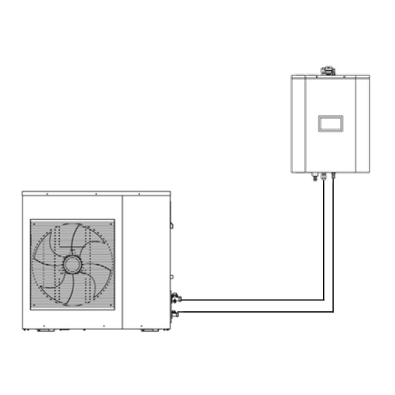
General Information The Lailey and Coates Split System consists of two major parts: The Internal and External Units. They are connected via refrigeration pipes and an ELV, shielded, communication Cable. The external units can either be wall mounted or hard-standing but should be secured via suitably designed mounting systems available from Lailey and Coates. -
Page 6: Technical Specification
Technical Specification Outdoor Unit LC-07 LC-10 LC-12 LC-15 Power supply 220-240v 50 Hz Nominal capacity * Heating 6.93 9.68 12.67 Nominal input * Heating 1.43 2.05 2.73 3.33 COP * 7⁰C (A7/W35) Heating 4.84 4.73 4.64 ⁰ C Outdoor temperature range ⁰ C ½ - �⁄�... -
Page 7: Installation Of External Unit
Installation of External Unit When locating the External Unit the following considerations should be taken into account: ● If wall mounting ensure that the structure is sufficiently solid to bear the weight of the unit without causing vibration. ● If floor mounted ensure base is solid with no likelihood of subsidence. ● Select a location so as to minimise disruption to neighbours and avoid close proximity to bedrooms. In accordance with MCS standards. ● Ensure adequate access to and around the unit for maintenance and non‐ restriction of airflow. ● Close proximity to possible gas leaks or electrical equipment should be avoided. ● When in defrost excess water will drain from the unit so ensure an adequate method of disposal to same. -
Page 8: Installation Of Internal Unit
Installation of Internal Unit When locating the Internal Unit the following considerations should be taken into account: ● If wall mounting ensure that the surface is flat, non‐combustible and sufficiently solid to bear the weight of the unit without causing vibration. ● Provision should be made for sufficient access to ensure ease of maintenance. ● Ensure the unit is not exposed to extremes of temperature. ● Avoid close proximity to possible inflammable gas leakage. ● Maximum refrigeration pipe length See page Please note: a wall bracket and mounting template are supplied with the Internal Unit. Installation Manual 2014 - Riv 2... -
Page 9: Wiring Instructions
Wiring Instructions Warnings This unit must be installed to conform with all relevant local standards and regulations by suitably qualified engineers. This unit must be earthed. Please ensure this unit has a suitable, dedicated power supply/supplies, and is not susceptible to frequent power loss via time clocks or other devices, etc. Suitably rated and protected cables should be used. -
Page 10: Rated Power Input And Fuse Information
Rated power input and fuse information Model Rated Outdoor Unit Indoor Unit Combined System Fuse Fuse Fuse Volts Watts Current Watts Current Watts Current Rating Rating Rating Amps Amps Amps Amps Amps Amps LC 07 220-240 3300 3054 14.4 6354 28.4 LC 10 220-240... -
Page 11: Indoor Electrical Connections
Indoor Electrical Connections 230 v Switching Only Hot Water ‘On’ To Zone Valve (unsuitable for mid-position type) Neutral Heating ‘On’ To Zone Valve (unsuitable for mid-position type) Solar Pump Secondary Hot Water Pump if Required - Port Valve - (Cooling option only. Not required) Secondary Heating Pump if Required Water Cylinder Electrical Heater (Immersion for Legionella) Boiler (not Required) -
Page 12: Plumbing Installation
Plumbing Installation Warnings This unit must be installed to conform with all relevant local standards and regulations by suitably qualified engineers. Installation should be capable of withstanding a maximum water pressure of 10 bar. Mid-position zone valves should not be used to switch between heating and hot water. Hydraulic zone valves are not suitable for use with this system. - Page 13 Plumbing Installation Continued Internal Pump Settings If used with radiators, pump should be set to AUTO ● If used with under floor heating, pump should be set to MANUAL and adjusted to ● Settings 1, 2 or 3 to achieve required flow rate as per table above. If a combination of radiators and under floor heating, pump should be set to ●...
-
Page 14: Refrigeration Installation
Refrigeration Installation. Warnings: This unit must be installed to conform with all relevant local standards and regulations by suitably qualified engineers. When brazing the pipe always use OFN. This unit is only suitable for R410A Refrigerant. This product contains fluorinated greenhouse gasses covered by the Kyoto Protocol. Do not vent gasses into atmosphere. - Page 15 Refrigeration Installation Continued Please note: ● Refrigerant pipes can be connected to either the top or bottom of the unit. If using top connections ensure bottom connections are tight and vice-versa. ● Pre‐Pressure Testing and Commissioning, ensure Service valves are open and Schrader valves are fully closed. Precautions when adding R410A Be sure to charge the specified amount of refrigerant in liquid state to the liquid pipe. As R 410A is a mixed refrigerant, adding it in gas form may cause the refrigerant composition to change, preventing normal operation.
-
Page 16: Dip Switch Settings
Dip Switch Settings Both internal and external Units have a bank of PCB dip switches. These should be checked prior to initial start-up to ensure correct operation of the Heat Pump. Any changes to these settings should be carried out with the Heat Pump powered down to enable the PCB to recognise these changes. -
Page 17: Pre-Operation Checklist
Pre-Operation Checklist Prior to initial start-up please ensure following: General: Dip Switches are correctly set to both External and Internal Units. See page There is no obvious damage to the body or components of the units. Units are securely fixed to walls/floor. Electrical: All cables are correctly terminated in appropriate connection blocks (i.e LV and ELV cables are not mixed up). -
Page 18: Commissioning
Commissioning After the initial installation the system needs to be commissioned, this document will explain and show how to set up and commission an air to water heat pump. Stage 1 - Electrical Check that the system wiring is complete and connected properly before switching on the power to the indoor and outdoor unit. -
Page 19: Lcd Controller
LCD controller Main Display Home Screen Date Time and Day indicator Timer Set Icon System Error Code Legionella Cycle Active Volt Free Indicator 18/06/2014 15:32 SUN Screen On / Off Actual temperatures of heating and Status hot water Parameters Required temperature Timers - See Page settings for heating and hot water... -
Page 20: How To Set Up Lcd Controller
How to set up LCD controller Setting the date, time and day. To access the time settings screen, touch the date, time and day indicator (1) on the controller home screen. Date Time and Day indicator 09/02/2013 09:12 TUES The controller will bleep and the screen will change to the following : Time Set- Date: Year... -
Page 21: Setting The Hot Water Temperature
Setting the Hot Water Temperature To set the hot water temperature, touch the ‘setting temperature’ as indicated. The controller will bleep and the screen will change to the following : Enter Enter the desired temperature and press enter. The display will revert to the home screen and the set temperature will be displayed. -
Page 22: Setting The Heating Water Temperature
Setting the Heating Water Temperature To set the heating water temperature, touch the ‘setting temperature’ as indicated. The controller will bleep and the screen will change to the following , enter the default access code 112233, then press enter. 112233 Enter The display will revert to the home screen. -
Page 23: Setting The Heat Pump Timer
Setting the Heat Pump Timer From the main display home screen, touch the timer icon (9). The controller will beep and the screen will change as follows: Heating Hot Water Timer Set Indicator Holiday Timer Within this screen there are two display grids for days of the week, the upper one is for heating the lower for hot water. - Page 24 Setting the Timer Continued Individual day timer screen - Heating Touch to close the screen IMPORTANT Touch to accept settings before closing this screen Within the individual day timer screen there are three pairs of on/off timers. In other words the system can be set to switch on and off three times during a 24 hour period.
- Page 25 Setting the Timer Continued 2) Once the time is set, select whether this is to start or stop the system by touching the corresponding power icon and selecting on or off. 3) The setting must then be enabled, to do this touch the enable icon and ensure that a green tick is visible.
-
Page 26: Holiday Timer
Holiday Timer To access the holiday timer touch the timer icon on the home screen. The daily timer screen will appear. Touch the Holiday icon and the holiday timer screen is displayed as below. 2013 / 99 / 99 Holiday Time date When the green ‘ON’... -
Page 27: Simple Trouble Shooting Guide
Access to change system parameters To gain access to the system parameters touch the parameters icon on the main home screen and the enter the following code 223344, followed by enter. Simple Trouble Shooting Guide This guide is to provide engineers a simple understanding of potential faults and how to rectify them. - Page 28 Simple Trouble Shooting Guide - Continued Low Pressure Fault This means that the heat pump system has detected a lower pressure, set on the low pressure switch. Causes - In Heating Dirty outdoor coils Poor airflow through the outdoor coils Outdoor fan failure Blockage in the pipe work ie liquid or expansion pipe Insufficient refrigerant (S O G) short of gas...
- Page 29 Simple Trouble Shooting Guide - Continued Compressor fail to start Each heat pump system will have a time delay on the compressor start operation if the compressor fails to start in a set number of times in 1 hour then a fault code will appear. Causes Low oil pressure Crank case heater fault...
-
Page 30: Fault / Error Codes
Fault / Error Codes Communication failure 1- Check correct specified cable has be installed between indoor and 2- Check connections between indoor and outdoor units see outdoor units page 8 3- Check the incoming power cable 4- Check indoor and outdoor PCBs 5- Check the output voltage is between 1.465 and 3.22 V dc LCD Controller 1 - Check LCD Connections... - Page 31 Fault / Error Codes Continued TC Electric heater temperature sensor failure 1 - Check TC Electric heater temperature sensor 2 - Check indoor PCB EEPROM Failure 1 - Check EEPROM 2 - Check indoor PCB Inverter current detector fault 1 - Check detector contact cables are firmly connected and not damaged 2 - Check Outdoor PCB Fixed speed compressor current detector fault...
- Page 32 Fault / Error Codes Continued P01 High Voltage Protection 1 - Check Power Supply 2 - Check the incoming power cable 3 - Check outdoor PCB P02 Low Voltage Protection 1 Check Power Supply 2 - Check the incoming power cable 3 - Check outdoor PCB P03 Inverter Module Protection 1 - Check Inverter Compressor...
- Page 33 Fault / Error Codes Continued P10 Fixed speed compressor current 1 - Check fixed speed compressor windings protection P11 Condenser high temperature 1 - Fan speeds protection 2 - Check EEV 3 - Check T3 coil temperature sensor 4 - Check outdoor PCB P12 Water flow switch FS protection 1 - Check water pump 2 - Check water flow switch...
-
Page 34: Commissioning Sheet
951 Yeovil Road Slough Trading Estate Slough Berkshire SL1 4NH Commissioning Sheet This form must be completed by the commissioning engineer and sent to Lailey and Coates at the above address. The Warranty on this unit cannot be issued until this form is received by Lailey and Coates. End User Name Phone Number Date of Attendance... - Page 35 Installation Related Adequate service space around the Isolating switches installed for heaters outdoor unit Provision made for drainage of Dip switches set on PC board if either outdoor unit thermostat or DHW cylinder has been installed Refrigeration Pipework Thermister installed in DHW cylinder in Insulated top pocket of ASHP in lower pocket for solar (Use heat conductive paste for...
Need help?
Do you have a question about the LC-07 and is the answer not in the manual?
Questions and answers