
Summary of Contents for Penguin Computing Niveus 4904GT
- Page 1 Niveus 4904GT Technical Guide Rev. 1.0 PENGUIN COMPUTING www.penguincomputing.com | 1-888-PENGUIN (736-4846) | twitter:@PenguinHPC...
- Page 2 Please Note: For the most up-to-date version of this manual, please see our web site at www.penguincomputing.com. Penguin Computing reserves the right to make changes to the product described in this manual at any time and without notice. This product, including software and documentation, is the property of Penguincomputing and/or its licensors, and is supplied only under a license.
-
Page 3: About This Manual
Preface Preface About this Manual This manual is written for professional system integrators and PC technicians. It provides information for the installation and use of the server. Installation and maintainance should be performed by experienced technicians only. Please refer to the server specifications page on our Web site for updates on supported memory, processors and operating systems (www.penguincomputing. -
Page 4: Table Of Contents
Niveus 4904GT User's Guide Contents Chapter 1 Introduction ................1-1 Overview ......................1-1 Serverboard Features ..................1-2 Processors ...................... 1-2 Memory ......................1-2 SATA ......................1-2 PCI Expansion Slots ..................1-2 Rear I/O Ports ....................1-2 IPMI ......................... 1-2 Chassis Features .................... 1-3 System Power .................... - Page 5 Preface Chapter 3 System Interface ..............3-1 Overview ......................3-1 Control Panel Buttons ..................3-2 Control Panel LEDs ..................3-2 Drive Carrier LEDs ..................3-3 Power Supply LEDs ..................3-4 Chapter 4 Standardized Warning Statements for AC Systems About Standardized Warning Statements ............4-1 Warning Definition ...................
- Page 6 Niveus 4904GT User's Guide Connector Definitions ................... 5-15 Power Connections ..................5-15 Control Panel Connections ................5-15 Other Connectors ..................5-18 Jumper Settings .................... 5-23 5-10 Onboard Indicators ..................5-26 5-11 SATA Ports ....................5-27 5-12 Onboard Battery .................... 5-28 Chapter 6 Advanced Chassis Setup ............6-1...
- Page 7 Preface Appendix B System Specifications ............B-1...
- Page 8 Niveus 4904GT User's Guide Notes...
-
Page 9: Chapter 1 Introduction
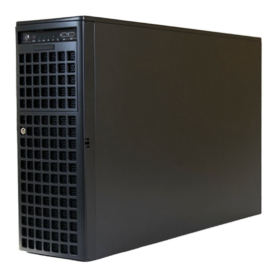
Chapter 1 Introduction Overview The workstation Niveus 4904gt is comprised of two main subsystems: the SC747BTQ-R2K02B 4U/Tower chassis and the X10DRG-Q dual Intel Xeon processor serverboard. Please refer to our web site for information on operating systems that have been certified for use with the system (www.penguincomputing. -
Page 10: Serverboard Features
User's Manual Serverboard Features At the heart of the Niveus 4904GT workstation lies the X10DRG-Q, a dual processor serverboard based on the Intel C612 Express chipset. Below are the main features of the serverboard. (See Figure 1-1 for a block diagram of the chipset). -
Page 11: Chassis Features
Chapter 1: Introduction Chassis Features The following is a general outline of the main features of the SC747BTQ-R2K02B chassis. System Power The chassis includes a 2000 W high-efficiency, hoto-plug, redundant (1+1) power supply consisting of two power supply modules. In the unlikely event a power supply module fails, replacement is simple. -
Page 12: Gpu Subsystem
User's Manual GPU Subsystem The Niveus 4904GT is a massively parallel-processing, quad-GPU server with support for up to four NVIDIA Tesla GPUs (such as Kepler K10, K20, K20X, K40, K80) and Xeon Phi Coprocessor GPUs, placing this system at the forefront of today's GPU computing solutions. - Page 13 Chapter 1: Introduction Figure 1-1. Intel C612 Express Chipset: System Block Diagram Note: This is a general block diagram. Please see Chapter 5 for details.
-
Page 14: Contacting Penguincomputing
Niveus 4904GT User's Manual Contacting Penguin Computing Headquarters Address: Penguin Computing 45800 Northport Loop West Fremont, CA 94538 U.S.A. +1 (888) 736-4846 Tel: +1 (415) 954-2899 Fax: marketing@penguincomputing.com (General Information) Email: support@penguincomputing.com (Technical Support) Website: www.penguincomputing.com... -
Page 15: Chapter 2 Rack Installation
Chapter 2: Rack Intallation Chapter 2 Rack Installation This chapter provides instructions for preparing and mounting your chassis in a rack. By default, the chassis is shipped configured as a tower. The tower top cover and bottom feet must be removed to mount in a rack. Also, the control panel/drive module should be rotated 90 degrees. -
Page 16: Warnings And Precautions
Niveus 4904GT User's Guide Warnings and Precautions Rack Precautions • Ensure that the leveling jacks on the bottom of the rack are fully extended to the floor with the full weight of the rack resting on them. • In single rack installations, stabilizers should be attached to the rack. -
Page 17: Rack Mounting Considerations
Chapter 2: Rack Intallation Rack Mounting Considerations Ambient Operating Temperature If installed in a closed or multi-unit rack assembly, the ambient operating tempera- ture of the rack environment may be greater than the ambient temperature of the room. Therefore, consideration should be given to installing the equipment in an environment compatible with the manufacturer’s maximum rated ambient tempera- ture (TMRA). -
Page 18: Procedure For Rack Mounting
Niveus 4904GT User's Guide Procedure for Rack Mounting This section provides information on installing a 4U chassis into a rack. There are a variety of rack units on the market, so the assembly procedure may differ slightly. Also refer to the installation instructions for your rack unit. - Page 19 Chapter 2: Rack Intallation Chassis Cover Chassis Foot Chassis Cover Lock Figure 2-1. Removing the Feet and Chassis Top Cover...
-
Page 20: Identifying The Sections Of The Rack Rails
Niveus 4904GT User's Guide Identifying the Sections of the Rack Rails The chassis package includes two rail assemblies. Each assembly consists of three sections: An inner rail that secures directly to the chassis, an outer rail that secures to the rack, and a middle rail which extends from the outer rail. These assemblies are specifically designed for the left and right side of the chassis. -
Page 21: Installing The Chassis Handles And Inner Rails
Chapter 2: Rack Intallation Installing the Chassis Handles and Inner Rails Installing the Inner Rails 1. Locate the chassis handles and handle screws. 2. Align the chassis handle with the front of the chassis and secure with the three chassis handle screws. 3. -
Page 22: Installing The Outer Rails Onto The Rack
Niveus 4904GT User's Guide Installing the Outer Rails onto the Rack Installing the Outer Rails 1. Press upward on the locking tab at the rear end of the middle rail. 2. Push the middle rail back into the outer rail. -
Page 23: Sliding The Chassis Onto The Rack Rails
Chapter 2: Rack Intallation Sliding the Chassis onto the Rack Rails Warning: Use a lift to hold the system while installing. Please follow safety recommendations printed on the rails. Installing the Chassis into a Rack 1. Extend the outer rails as illustrated above. 2. -
Page 24: Tower Configuration Instructions
Niveus 4904GT User's Guide Tower Configuration Instructions The 4U chassis is shipped with the tower top cover and feet pre-installed. To use the chassis as a desktop server, no other installation is required. Use the instructions in this section if you have converted the chassis for rack use and need to return the chassis to tower orientation. -
Page 25: Chapter 3 System Interface
Chapter 3: System Interface Chapter 3 System Interface Overview The chassis includes the following user interface elements: • A control panel on the front that includes power buttons and status monitoring lights • Status lights on externally accessible hard drives •... -
Page 26: Control Panel Buttons
Niveus 4904GT User's Manual Control Panel Buttons The chassis includes two push-buttons that control power to the system. Power: The main power switch is used to apply or remove power from the power supply to the server. Turning off system power with this button removes the main power but maintains standby power. -
Page 27: Drive Carrier Leds
Chapter 3: System Interface Information LED: Alerts operator of several states, as noted in the table below. Information LED Status Description An overheat condition has occured. Continuously on and red (This may be caused by cable congestion.) Blinking red (1Hz) Fan failure, check for an inoperative fan. -
Page 28: Power Supply Leds
Niveus 4904GT User's Manual Power Supply LEDs On the rear of the power supply module, an LED displays the status. • Solid Green: When illuminated, indicates that the power supply is on. • Solid Amber: When illuminated, indicates the power supply is plugged in and turned off, or the system is off but in an abnormal state. -
Page 29: Chapter 4 Standardized Warning Statements For Ac Systems
Only certified technicians should attempt to install or configure components. Read this chapter in its entirety before installing or configuring components in the Penguin Computing chassis. Some warnings may not apply for your system. Warning Definition Warning! This warning symbol means danger. You are in a situation that could cause bodily injury. - Page 30 Niveus 4904GT User's Manual Warnung WICHTIGE SICHERHEITSHINWEISE Dieses Warnsymbol bedeutet Gefahr. Sie befinden sich in einer Situation, die zu Verletzungen führen kann. Machen Sie sich vor der Arbeit mit Geräten mit den Gefahren elektrischer Schaltungen und den üblichen Verfahren zur Vorbeugung vor Unfällen vertraut.
- Page 31 Chapter 4: Warning Statements for AC Systems 안전을 위한 주의사항 경고! 이 경고 기호는 위험이 있음을 알려 줍니다. 작업자의 신체에 부상을 야기 할 수 있는 상태에 있게 됩니다. 모든 장비에 대한 작업을 수행하기 전에 전기회로와 관련된 위험요소들을 확인하시고 사전에 사고를 방지할 수 있도록 표준 작업절차를...
-
Page 32: Installation Instructions
Niveus 4904GT User's Manual Installation Instructions Warning! Read the installation instructions before connecting the system to the power source. 設置手順書 システムを電源に接続する前に、 設置手順書をお読み下さい。 警告 将此系统连接电源前,请先阅读安装说明。 警告 將系統與電源連接前,請先閱讀安裝說明。 Warnung Vor dem Anschließen des Systems an die Stromquelle die Installationsanweisungen lesen. ¡Advertencia! Lea las instrucciones de instalación antes de conectar el sistema a la red de alimentación. -
Page 33: Circuit Breaker
Chapter 4: Warning Statements for AC Systems Circuit Breaker Warning! This product relies on the building's installation for short-circuit (overcurrent) protection. Ensure that the protective device is rated not greater than: 250 V, 20 A. サーキッ ト ・ ブレーカー この製品は、 短絡 (過電流) 保護装置がある建物での設置を前提としています。 保護装置の定格が250 V、... -
Page 34: Power Disconnection Warning
Niveus 4904GT User's Manual 경고! 이 제품은 전원의 단락(과전류)방지에 대해서 전적으로 건물의 관련 설비에 의존합니다. 보호장치의 정격이 반드시 250V(볼트), 20A(암페어)를 초과하지 않도록 해야 합니다. Waarschuwing Dit product is afhankelijk van de kortsluitbeveiliging (overspanning) van uw electrische installatie. Controleer of het beveiligde aparaat niet groter gedimensioneerd is dan 220V, 20A. - Page 35 Chapter 4: Warning Statements for AC Systems ¡Advertencia! El sistema debe ser disconnected de todas las fuentes de energía y del cable eléctrico quitado de los módulos de fuente de alimentación antes de tener acceso el interior del chasis para instalar o para quitar componentes de sistema. Attention Le système doit être débranché...
-
Page 36: Equipment Installation
Niveus 4904GT User's Manual Equipment Installation Warning! Only trained and qualified personnel should be allowed to install, replace, or service this equipment. 機器の設置 トレーニングを受け認定された人だけがこの装置の設置、 交換、 またはサービスを許可 されています。 警告 只有经过培训且具有资格的人员才能进行此设备的安装、更换和维修。 警告 只有經過受訓且具資格人員才可安裝、更換與維修此設備。 Warnung Das Installieren, Ersetzen oder Bedienen dieser Ausrüstung sollte nur geschultem, qualifiziertem Personal gestattet werden. -
Page 37: Restricted Area
Chapter 4: Warning Statements for AC Systems Waarschuwing Deze apparatuur mag alleen worden geïnstalleerd, vervangen of hersteld door geschoold en gekwalificeerd personeel. Restricted Area Warning! This unit is intended for installation in restricted access areas. A restricted access area can be accessed only through the use of a special tool, lock and key, or other means of security. -
Page 38: Battery Handling
Niveus 4904GT User's Manual 경고! 이 장치는 접근이 제한된 구역에 설치하도록 되어있습니다. 특수도구, 잠금 장치 및 키, 또는 기타 보안 수단을 통해서만 접근 제한 구역에 들어갈 수 있습니다. Waarschuwing Dit apparaat is bedoeld voor installatie in gebieden met een beperkte toegang. - Page 39 Chapter 4: Warning Statements for AC Systems Warnung Bei Einsetzen einer falschen Batterie besteht Explosionsgefahr. Ersetzen Sie die Batterie nur durch den gleichen oder vom Hersteller empfohlenen Batterietyp. Entsorgen Sie die benutzten Batterien nach den Anweisungen des Herstellers. Attention Danger d'explosion si la pile n'est pas remplacée correctement. Ne la remplacer que par une pile de type semblable ou équivalent, recommandée par le fabricant.
-
Page 40: Redundant Power Supplies (If Applicable To Your System)
Niveus 4904GT User's Manual Redundant Power Supplies (if applicable to your system) Warning! This unit might have more than one power supply connection. All connections must be removed to de-energize the unit. 冗長電源装置 このユニッ トは複数の電源装置が接続されている場合があります。 ユニッ トの電源を切るためには、 すべての接続を取り外さなければなりません。 警告 此部件连接的电源可能不止一个,必须将所有电源断开才能停止给该部件供电。... -
Page 41: Backplane Voltage (If Applicable To Your System)
Chapter 4: Warning Statements for AC Systems 경고! 이 장치에는 한 개 이상의 전원 공급 단자가 연결되어 있을 수 있습니다. 이 장치에 전원을 차단하기 위해서는 모든 연결 단자를 제거해야만 합니다. Waarschuwing Deze eenheid kan meer dan één stroomtoevoeraansluiting bevatten. Alle aansluitingen dienen verwijderd te worden om het apparaat stroomloos te maken. -
Page 42: Comply With Local And National Electrical Codes
Niveus 4904GT User's Manual 경고! 시스템이 동작 중일 때 후면판 (Backplane)에는 위험한 전압이나 에너지가 발생 합니다. 서비스 작업 시 주의하십시오. Waarschuwing Een gevaarlijke spanning of energie is aanwezig op de backplane wanneer het systeem in gebruik is. Voorzichtigheid is geboden tijdens het onderhoud. -
Page 43: Product Disposal
Chapter 4: Warning Statements for AC Systems Attention L'équipement doit être installé conformément aux normes électriques nationales et locales. 경고! 현 지역 및 국가의 전기 규정에 따라 장비를 설치해야 합니다. Waarschuwing Bij installatie van de apparatuur moet worden voldaan aan de lokale en nationale elektriciteitsvoorschriften. -
Page 44: Hot Swap Fan Warning (If Applicable To Your System)
Niveus 4904GT User's Manual ¡Advertencia! Al deshacerse por completo de este producto debe seguir todas las leyes y reglamentos nacionales. Attention La mise au rebut ou le recyclage de ce produit sont généralement soumis à des lois et/ou directives de respect de l'environnement. Renseignez-vous auprès de l'organisme compétent. - Page 45 Chapter 4: Warning Statements for AC Systems 警告 當您從機架移除風扇裝置,風扇可能仍在轉動。小心不要將手指、螺絲起子和其他 物品太靠近風扇。 Warnung Die Lüfter drehen sich u. U. noch, wenn die Lüfterbaugruppe aus dem Chassis genommen wird. Halten Sie Finger, Schraubendreher und andere Gegenstände von den Öffnungen des Lüftergehäuses entfernt. ¡Advertencia! Los ventiladores podran dar vuelta cuando usted quite ell montaje del ventilador del chasis.
-
Page 46: Power Cable And Ac Adapter
Electrical Appliance and Material Safety Law prohibits the use of UL or CSA -certified cables (that have UL/CSA shown on the code) for any other electrical devices than products designated by Penguin Computing only. 電源コードとACアダプター... - Page 47 Chapter 4: Warning Statements for AC Systems Attention Lors de l'installation du produit, utilisez les bables de connection fournis ou désigné. L'utilisation d'autres cables et adaptateurs peut provoquer un dysfonctionnement ou un incendie. Appareils électroménagers et de loi sur la sécurité Matériel interdit l'utilisation de UL ou CSA câbles certifiés qui ont UL ou CSA indiqué...
- Page 48 Niveus 4904GT User's Manual Notes 4-20...
-
Page 49: Chapter 5 Advanced Serverboard Setup
Chapter 5: Advanced Serverboard Setup Chapter 5 Advanced Serverboard Setup This chapter covers the steps required to connect cables and describes all jumpers and connections. A layout and quick reference chart are included in this chapter for your reference. Always close the chassis when you have finished working on the system to maintain optimal cooling. -
Page 50: Connecting Cables
24-pin and the 8-pin power connectors to your power supply for adequate power delivery to your system. The 4-pin connector is optional, however, Penguin Computing recommends that this connector also be plugged in for optimal power delivery. -
Page 51: I/O Ports
Chapter 5: Advanced Serverboard Setup I/O Ports Figure 5-1. Rear I/O Ports Rear I/O Ports 1. COM1 Port 2. USB 3.0 Port 4 3. USB 3.0 Port 5 4. IPMI Dedicated LAN 5. USB 2.0 Port 0 6. USB 2.0 Port 1 7. -
Page 52: Installing The Processor And Heatsink
• Install the processor into the CPU socket before installing the heatsink. • Refer to the Penguin Computing web site for updates on CPU support. Installing an LGA 2011 Processor Installing a CPU 1. There are two levers on the LGA 2011 socket. - Page 53 Chapter 5: Advanced Serverboard Setup 3. W ith the sec ond lever f ully Open the load plate. retracted, gently push down on the "Open 1st" lever to loosen the load plate. Lift the load plate with your fingers to open it completely. 4.
- Page 54 Niveus 4904GT User's Manual Gently close 7. With the "Close 1st" lever fully the load plate. retracted, gently close the load plate. Push down and lock the lever labeled "Close 1st". 8. Make sure the locking mechanism on the "Close 1st" lever catches the lip of the load plate.
-
Page 55: Installation And Removal Of The Heatsink
Chapter 5: Advanced Serverboard Setup Installation and Removal of the Heatsink Installing the Heatsink Do not apply any thermal grease to the heatsink or the CPU die; the required amount has already been applied 1. Place the heatsink on top of the CPU so that the four mounting holes are aligned with those on the retention... -
Page 56: Installing Memory
The X10DRG-Q serverboard supports up to 1 TB of 288-pin registered (RDIMM) DDR4 ECC 1333/1600/1866/2133 MHz in 16 slots. DIMM sizes up to 64GB @ 1.2V. Can be used. See the following table for memory installation. For the latest memory updates, please refer to the Penguin Computing website. -
Page 57: Processor & Memory Module Population Configuration
Chapter 5: Advanced Serverboard Setup Processor & Memory Module Population Configuration For memory to work properly, follow the tables below for memory population. Processors and their Corresponding Memory Modules CPU# Corresponding DIMM Modules CPU 1 DIMMB1 DIMMC1 DIMMB2 DIMMC2 DIMMA1 DIMMD1 DIMMA2 DIMMD2... -
Page 58: Populating Lrdimm And Rdimm Ecc Memory Modules
Niveus 4904GT User's Manual Populating LRDIMM and RDIMM ECC Memory Modules Note: For the memory modules to work properly, install DIMM modules of the same type, same speed and same operating frequency. Mixing of RDIMMs, UDIMMs or LRDIMMs is not allowed. Do not install both ECC and Non-ECC memory modules on the same serverboard. - Page 59 Chapter 5: Advanced Serverboard Setup Installing an Expansion Card 1. Locate the release tab on the top of the PCI slot bracket. Gently apply pressure to the middle of the release tab to unlock the PCI slot bracket. 2. Pull the release tab upward. 3.
-
Page 60: Serverboard Details
Niveus 4904GT User's Manual Serverboard Details Figure 5-4. X10DRG-Q Layout (not drawn to scale) Notes: • "■" indicates the location of "Pin 1". • Jumpers/LED Indicators not indicated are for internal testing only. 5-12... - Page 61 Chapter 5: Advanced Serverboard Setup Connectors Connectors Description Audio_FP High Definition (HD) 7.1-channel audio header for front access Battery (JBT1) Onboard CMOS battery (See Chpt. 3 for used battery disposal) COM1/COM2 Back-panel COM Port 1/Serial Port 2 for front access FAN 1/2/3/4/5/6, CPU/system cooling fan headers (Fans 1-6, Fans A-D) FAN A/B/C/D...
- Page 62 Niveus 4904GT User's Manual (CPU1) SLOT10 PCI-Exp. 3.0 x8 in x16 slot supported by CPU1 (CPU2) SLOT11 PCI-Exp. 3.0 x8 slot supported by CPU2 (BP) USB 0/1 (2.0) Backpanel USB 2.0 ports 0/1 (BP) USB 4/5 (3.0) Backpanel USB 3.0 ports 4/5 (FP) USB 2/3 (2.0)
-
Page 63: Connector Definitions
Pins Definition Pins Definition The 4-pin connector is optional, however, 1~ 4 Ground Ground Penguin computing recommends that this +12V +12V connector also be plugged in for optimal Required Connections power delivery. Control Panel Connections Figure 5-5. - Page 64 Niveus 4904GT User's Manual NMI Button NMI Button Pin Definitions (JF1) The non-maskable interrupt button Pin# Definition header is located on pins 19 and 20 Control of JF1. Refer to the table on the right Ground for pin definitions. Power LED Pin...
- Page 65 Chapter 5: Advanced Serverboard Setup Power Fail LED PWR Fail LED Pin Definitions The Power Fail LED connection (JF1) is located on pins 5 and 6 of JF1. Pin# Definition Refer to the table on the right for pin 3.3V definitions.
-
Page 66: Other Connectors
Niveus 4904GT User's Manual Other Connectors Serial Ports Serial COM Ports Pin Definitions Two COM connections (COM1 & Pin # Definition Pin # Definition COM2) are located on the serverboard. COM1 is located on the rear I/O panel. COM2, located close to PCI-E CPU1 Slot1, provides front access support. - Page 67 Chapter 5: Advanced Serverboard Setup Unit Identifier Switch UID Switch Pin Definitions A Unit Identifier (UID) switch and Pin# Definition two LED Indicators are located on Ground the serverboard. The UID switch is Ground located next to LAN2 port on the rear Button In I/O panel.
- Page 68 Niveus 4904GT User's Manual Internal Speaker Internal Buzzer Pin Definition The Internal Speaker (SP1) provides Pin# Definitions audible indications for various beep Pin 1 Pos. (+) Beep In codes. See the table on the right for pin Pin 2 Neg. (-) Alarm Speaker definitions.
- Page 69 Chapter 5: Advanced Serverboard Setup Chassis Intrusion Chassis Intrusion Pin Definitions A Chassis Intrusion header is located Pin# Definition at JL1 on the serverboard. Attach an Intrusion Input appropriate cable from the chassis to Ground inform you of a chassis intrusion when the chassis is opened.
- Page 70 Niveus 4904GT User's Manual Front Panel Audio Header 10-in Audio Pin Definitions Front Panel Audio header is located Pin# Signal at AUDIO_FP. Connect a cable to Microphone_Left this header to use front panel audio Audio_Ground device. To use the FP Audio for '97...
-
Page 71: Jumper Settings
Chapter 5: Advanced Serverboard Setup Jumper Settings Explanation of Jumpers To modify the operation of the serverboard, jumpers can be used to choose between optional settings. Jumpers create shorts between two pins to change the function of the connector. Pin 1 is identified with a square solder pad on the printed circuit board. - Page 72 Niveus 4904GT User's Manual VGA Enable/Disable VGA Enable/Disable Jumper Settings JPG1 allows you to enable or disable Jumper Setting Definition the VGA port. The default position is on Pins 1-2 pins 1 and 2 to enable VGA. See the Enabled Pins 2-3 table on the right for jumper settings.
- Page 73 Chapter 5: Advanced Serverboard Setup Manufacturer Mode Select ME Mode Select Jumper Settings Close pins 2 and 3 of Jumper JPME2 Jumper Setting Definition to bypass SPI flash security and Normal (Default) force the system to operate in the Manufacture Mode Manufacturer mode, which will allow the user to flash the system firmware from a host server for system setting...
-
Page 74: 5-10 Onboard Indicators
Niveus 4904GT User's Manual 5-10 Onboard Indicators Activity LED Link LED GLAN LEDs There are two GLAN ports on the serverboard. An additional IPMI Activity LED Link LED dedicated LAN port is also located above the USB 0/1 ports on the backpanel. -
Page 75: 5-11 Sata Ports
Chapter 5: Advanced Serverboard Setup BMC Heartbeat LED BMC Heartbeat LED Status A BMC Heartbeat LED is located at Color/State Definition LEDM1. When LEDM1 is blinking, Green: BMC: Normal BMC functions normally. See the table Blinking at right for more information. 5-11 SATA Ports Serial ATA 3.0 Ports Serial ATA... -
Page 76: 5-12 Onboard Battery
Niveus 4904GT User's Manual 5-12 Onboard Battery Please handle used batteries carefully. Do not damage the battery in any way; a damaged battery may release hazardous materials into the environment. Do not discard a used battery in the garbage or a public landfill. Please comply with the regulations set up by your local hazardous waste management agency to dispose of your used battery properly. - Page 77 Chapter 5: Advanced Serverboard Setup Notes 5-29...
- Page 78 Niveus 4904GT User's Manual 5-30...
-
Page 79: Chapter 6 Advanced Chassis Setup
Chapter 6: Advanced Chassis Setup Chapter 6 Advanced Chassis Setup This chapter covers the steps required to install components and perform maintenance on the SC747BTQ-R2K02B chassis. The only tool required is a Phillips screwdriver. Your system may require the installation of processors, memory, drives or expansion cards. -
Page 80: Static-Sensitive Devices
Niveus 4904GT User's Manual Static-Sensitive Devices Electrostatic Discharge (ESD) can damage electronic com ponents. To prevent damage to any printed circuit boards (PCBs), it is important to handle them very carefully. The following measures are generally sufficient to protect your equipment from... -
Page 81: Control Panel Orientation
Chapter 6: Advanced Chassis Setup Control Panel Orientation The server can be configured for either tower or server rack orientation. It is shipped in tower mode and can be immediately used as desktop server. To use it in a rack, rotate the module that contains the control panel and the three drive trays (#1 in Figure 6-3) 90 degrees. - Page 82 Niveus 4904GT User's Manual Rotating the Control Panel/Drive Module for Rack Mounting 1. Open the chassis cover. 2. Locate the control panel/drive module and disconnect any cables from the module to any component in the chassis. 3. Push the module release lever to unlock the module. (Figure 6-5) 4.
-
Page 83: 6-3 Configuring Drives
Chapter 6: Advanced Chassis Setup 6-3 Configuring Drives The default configuration includes eight hot-swap hard disk drives plus three full size drive trays for removable media drives or additional hard disk drives. Configuring the 5.25" Drive Bays The control panel/drive module includes three 5.25" drive bays under the front control panel. - Page 84 Niveus 4904GT User's Manual Drive Tray Hard Drive Figure 6-7. Add a Hard Drive to the Drive Tray 4. Place the hard drive in the drive tray. The hard drive may not completely fill the tray (Figure 6-7). 5. Secure the hard drive to the tray with four screws from the bottom.
- Page 85 Chapter 6: Advanced Chassis Setup Adding Peripheral Drives to the Drive Bays Replace a drive tray with a peripheral drive. 1. Open the chassis cover. 2. Locate the release tab for the drive tray where you want to place the peripheral drive (Figure 6-8).
-
Page 86: Additional Hard Drives
Niveus 4904GT User's Manual Additional Hard Drives The chassis accepts a CSE-M35BP mobile rack in place of the three bays just under the control panel. This configuration yields a total of thirteen hot-swap hard drives and no peripheral drives. Installing the M35 Mobile Rack 1. -
Page 87: Installing Drives In The Default Hdd Bays
Chapter 6: Advanced Chassis Setup Installing Drives in the Default HDD Bays Hard drives in the eight default HDD bays are mounted in drive carriers to simplify their installation and removal. These carriers also help promote proper airflow for the drive bays. Installing Hard Drives 1. - Page 88 Niveus 4904GT User's Manual 3. Remove the screws holding the drive carrier to the dummy drive. 4. Place a hard drive in the drive carrier (Figure 6-11). Drive Carrier SAS/SATA Drive Figure 6-11. Installing the Hard Drive Figure 6-12. Securing Drive 5.
-
Page 89: System Cooling
Chapter 6: Advanced Chassis Setup System Cooling Heavy-duty fans provide cooling for the chassis. Four fans are located in the mid- section of the chassis, two fans are located in the rear, and two optional fans can be mounted on the external rear of the chassis. The internal fans come pre-installed to the chassis. - Page 90 Niveus 4904GT User's Manual FAN-0114L4 Mid Fan Release Tab FAN-0138L4 Figure 6-13. Mid-System Chassis Fans FAN-0082L4 Rear Fan Release Figure 6-14. Rear System Chassis Fans 6-12...
-
Page 91: Installing The Gpu Kit
Chapter 6: Advanced Chassis Setup Installing the GPU Kit When using passive GPUs, you must use the GPU cooling kit, MCP-320-74701-0N- KIT. This kit consists of two fans with brackets that can be attached to the back of the chassis and one mylar air shroud to concentrate air flow to the GPUs. Installing External Rear Fans 1. - Page 92 Niveus 4904GT User's Manual Mounting Screws Mounting Pins Figure 6-16. Placing the External Rear Fan and Bracket on the Chassis 4. Place two metal mounting pins into the holes in the chassis at the base of the PCI slots in the position where the fan is to be located. Tighten these pins to the rear window using pliers.
- Page 93 Chapter 6: Advanced Chassis Setup Figure 6-17. PCI Slot Latches 7. Remove the PCI slot snap latch to allow the fan cable access. a. Determine which PCI slot aligns with the slot in the top of the fan bracket. b. Open the PCI slot snap latch by pressing downward on the latch to open it. c.
- Page 94 Niveus 4904GT User's Manual Figure 6-18. Dummy GPU for Air Flow 12. If you do not fill all the GPU slots, install a PCI card dummy (part number MCP- 240-00096-0N). This facilitates proper air flow for the GPUs. 13. Install the GPU air shroud. (Figure 6-19) 14.
- Page 95 Chapter 6: Advanced Chassis Setup Figure 6-19. GPU Kit Air Shroud Installed 6-17...
- Page 96 Niveus 4904GT User's Manual Replacing External Fans External fans can be replaced during system operation. 1. Visually inpect the fans to determine which one has failed. 2. Press the release tab on the top of the fan and pull the fan from the bracket.
-
Page 97: Power Supply
Chapter 6: Advanced Chassis Setup Power Supply This chassis features an auto-switching power supply. This enables it to automatically sense and operate at a 100v to 240v input voltage. An amber light will be illuminated when the power is off. An green light indicates that the power supply is operating. Replacing the Power Supply With a redundant power supply, the system automatically switches to the second power supply if the first should fail. -
Page 98: Power Supply Connections
Niveus 4904GT User's Manual Power Supply Connections Connect each of the following cables, as required, by your serverboard manufacturer. In some instances, some cables may not need to be connected. Some cables may not be available with your model. Power Supply Cables... - Page 99 Chapter 6: Advanced Chassis Setup Notes 6-21...
-
Page 100: Chapter 7 Bios
Chapter 7: AMI BIOS Chapter 7 BIOS Introduction This chapter describes the AMI BIOS Setup utility for the X10DRG-Q. It also pro- vides the instructions on how to navigate the AMI BIOS Setup utility screens. The AMI ROM BIOS is stored in a Flash EEPROM and can be easily updated. Starting BIOS Setup Utility To enter the AMI BIOS Setup utility screens, press the <Del>... -
Page 101: How To Change The Configuration Data
Niveus 4904GT User’s Manual How To Change the Configuration Data The configuration data that determines the system parameters may be changed by entering the AMI BIOS Setup utility. This Setup utility can be accessed by pressing <F2> at the appropriate time during system boot. - Page 102 Chapter 7: AMI BIOS System Date This item displays the system date in Day MM/DD/YY format (e.g. Wed 10/12/2011). System Time This item displays the system time in HH:MM:SS format (e.g. 15:32:52).
-
Page 103: Advanced Setup Configurations
Niveus 4904GT User’s Manual Advanced Setup Configurations Use the arrow keys to select Advanced Setup and press <Enter> to access the following submenu items. Boot Features Quiet Boot This feature selects the bootup screen display between POST messages and the OEM logo. Select Disabled to display the POST messages. Select Enabled to display the OEM logo instead of the normal POST messages. -
Page 104: Power Configuration
Chapter 7: AMI BIOS Interrupt 19 Capture Interrupt 19 is the software interrupt that handles the boot disk function. When this item is set to Enabled, the ROM BIOS of the host adaptors will "capture" Interrupt 19 at bootup and allow the drives that are attached to these host adaptors to func- tion as bootable disks. -
Page 105: Cpu Configuration
Niveus 4904GT User’s Manual CPU Configuration This submenu displays the information of the CPU as detected by the BIOS. It also allows the user to configuration CPU settings. Socket 1 CPU Information/Socket 2 CPU Information This submenu displays the following information regarding the CPU installed in Socket 1 and (or) Socket 2 as detected by the BIOS. - Page 106 Chapter 7: AMI BIOS Execute Disable Bit Capability (Available if supported by the OS & the CPU) Select Enabled to enable the Execute-Disable Bit which will allow the processor to designate areas in the system memory where an application code can execute and where it cannot, thus preventing a worm or a virus from flooding illegal codes to overwhelm the processor or damage the system during an attack.
- Page 107 Niveus 4904GT User’s Manual Intel ® Virtualization Technology (Available when supported by the CPU) Select Enabled to support Intel ® Virtualization Technology, which will allow one platform to run multiple operating systems and applications in independent parti- tions, creating multiple "virtual" systems in one physical computer. The options are Enabled and Disabled.
-
Page 108: Chipset Configuration
Chapter 7: AMI BIOS CPU C State Control Package C State limit This feature allows the user to set the limit on the C-State package register. The options are C0/C1 State, C2 State, C6 (Non Retention) State, and C6 (Rententioin) State. CPU C3 Report Select Enabled to allow the BIOS to report the CPU C3 State (ACPI C2) to the operating system. - Page 109 Niveus 4904GT User’s Manual IIO1 Configuration / IIO2 Configuration II01 PORT 1A Link Speed This item configures the link speed of a PCI-E port specified by the user. The options are Gen 1 (Generation 1) (2.5 GT/s), Gen 2 (Generation 2) (5 GT/s) and Gen 3 (Generation 3) (8 GT/s).
- Page 110 Chapter 7: AMI BIOS IO Acceleration) Configuration IOAT (Intel ® Enable IOAT Select Enable to enable Intel I/OAT (I/O Acceleration Technology) support, which significantly reduces CPU overhead by leveraging CPU architectural improve- ments and freeing the system resource for other tasks. The options are Enable and Disable.
-
Page 111: Memory Configuration
Niveus 4904GT User’s Manual • Current QPI Link Frequency • QPI Global MMIO Low Base/Limit • QPI Global MMIO High Base/Limit • QPI PCIe Configuration Base/Size Link Frequency Select Use this item to select the CPU Frequency. The options are 6.4 GB/s, 8.0 GB/s, 9.6 GB/s, Auto, Auto Limited. - Page 112 Chapter 7: AMI BIOS Data Scrambling Select Enabled to enable data scrambling to enhance system performance and data integrity. The options are Auto, Disabled and Enabled. DRAM RAPL Baseline Use this feature to set the run-time power-limit baseline for DRAM modules. The options are Disable, DRAM RAPL Mode 0, and DRAM RAPL Mode 1.
-
Page 113: South Bridge Configuration
Niveus 4904GT User’s Manual Memory Rank Sparing Select Enable to enable memory-sparing support for memory ranks to improve memory performance. The options are Disabled and Enabled. Patrol Scrub Patrol Scrubbing is a process that allows the CPU to correct correctable memory errors detected on a memory module and send the correction to the requestor (the original source). - Page 114 Chapter 7: AMI BIOS XHCI Hand-Off This is a work-around solution for operating systems that do not support XHCI (Ex- tensible Host Controller Interface) hand-off. The XHCI ownership change should be claimed by the XHCI driver. The settings are Enabled and Disabled. EHCI Hand-Off This item is for operating systems that do not support Enhanced Host Controller Interface (EHCI) hand-off.
-
Page 115: Sata Configuration
Niveus 4904GT User’s Manual Azalia Select Enabled to enable support for Azalia High Definition Audio. The options are Disabled, Enabled, and Auto. Azalia PME Enable Select Enabled to enable power management capability of the Azalia controller. The settings are Enabled and Disabled. - Page 116 Chapter 7: AMI BIOS Port 0 ~ Port 5 Hot Plug Select Enabled to enable hot-plugging support for a port specified by the user, which will allow the user to replace a SATA disk drive installed on this port without shutting down the system.
- Page 117 Niveus 4904GT User’s Manual • Model number of drive and capacity • Software Preserve Support Port 0~ Port 5 Select Enabled to enable a SATA port specified by the user. The options are Disabled and Enabled. Port 0 ~ Port 5 Hot Plug...
- Page 118 Chapter 7: AMI BIOS Support Aggressive Link Power Management When this item is set to Enabled, the SATA AHCI controller manages the power usage of the SATA link. The controller will put the link to a low power state when the I/O is inactive for an extended period of time, and the power state will return to normal when the I/O becomes active.
- Page 119 Niveus 4904GT User’s Manual *If the item above "Configure sSATA as" is set to RAID, the following items will display: Support Aggressive Link Power Management When this item is set to Enabled, the SATA AHCI controller manages the power usage of the SATA link. The controller will put the link to a low power state when the I/O is inactive for an extended period of time, and the power state will return to normal when the I/O becomes active.
- Page 120 Chapter 7: AMI BIOS Server ME (Management Engine) Configuration This feature displays the following system ME configuration settings. • General ME Configuration • Operational Firmware Version • Recovery Firmware Version • ME Firmware Features • ME Firmware Status #1 • ME Firmware Status #2 •...
- Page 121 Niveus 4904GT User’s Manual Maximum Read Request Select Auto for the system BIOS to automatically set the maximum size for a read request for a PCI-E device to enhance system performance. The options are Auto, 128 Bytes, 256 Bytes, 512 Bytes, 1024 Bytes, 2048 Bytes, and 4096 Bytes.
-
Page 122: Super Io Configuration
Chapter 7: AMI BIOS VGA Priority Use this item to select the graphics device to be used as the primary video display for system boot. The options are Onboard and Offboard. Network Stack Select Enabled to enable PXE (Preboot Execution Environment) or UEFI (Uni- fied Extensible Firmware Interface) for network stack support. -
Page 123: Serial Port Console Redirection
Niveus 4904GT User’s Manual Serial Port Console Redirection COM 1 COM 1 Console Redirection Select Enabled to enable COM Port 1 Console Redirection, which will allow a client machine to be connected to a host machine at a remote site for networking. The options are Disabled and Enabled. - Page 124 Chapter 7: AMI BIOS Stop Bits A stop bit indicates the end of a serial data packet. Select 1 Stop Bit for standard serial data communication. Select 2 Stop Bits if slower devices are used. The options are 1 and 2. Flow Control Use this item to set the flow control for Console Redirection to prevent data loss caused by buffer overflow.
- Page 125 Niveus 4904GT User’s Manual SOL/COM2 Console Redirection Select Enabled to use the SOL port for Console Redirection. The options are Enabled and Disabled. *If the item above set to Enabled, the following items will become available for user's configuration: SOL/COM2 Console Redirection Settings Use this feature to specify how the host computer will exchange data with the client computer, which is the remote computer used by the user.
- Page 126 Chapter 7: AMI BIOS Flow Control Use this feature to set the flow control for Console Redirection to prevent data loss caused by buffer overflow. Send a "Stop" signal to stop sending data when the receiving buffer is full. Send a "Start" signal to start data-sending when the receiving buffer is empty.
-
Page 127: Acpi Settings
Niveus 4904GT User’s Manual Terminal Type Use this feature to select the target terminal emulation type for Console Redirec- tion. Select VT100 to use the ASCII character set. Select VT100+ to add color and function key support. Select ANSI to use the extended ASCII character set. - Page 128 Chapter 7: AMI BIOS PCI AER (Advanced Error-Reporting) Support Select Enabled to support Advanced Error-Reporting for onboard PCI devices. The options are Disabled and Enabled. Thunderbolt Intel ® The following Thunderbolt information will be displayed: • Intel ® Thunderbolt Configuration •...
- Page 129 Niveus 4904GT User’s Manual SMI/Notify Support Select Enabled to enable the SMI notification support. The options are Enabled and Disabled.. SwSMI Support Select Enabled to enable software SMI support in ASL code. The options are En- abled and Disabled. Notify Support Select Enabled to enable notification support in ASL code.
-
Page 130: Event Logs
Chapter 7: AMI BIOS Event Logs Use this feature to configure Event Log settings. Change SMBIOS Event Log Settings This feature allows the user to configure SMBIOS Event settings. Enabling/Disabling Options SMBIOS Event Log Select Enabled to enable SMBIOS (System Management BIOS) Event Logging during system boot. - Page 131 Niveus 4904GT User’s Manual PCI-Ex (PCI-Express) Error Enable Select Yes for the BIOS to correct errors occurred in the PCI-E slots. The options are Yes and No. Erasing Settings Erase Event Log Select Enabled to erase all error events in the SMBIOS (System Management BIOS) log before an event logging is initialized at bootup.
-
Page 132: Ipmi
Chapter 7: AMI BIOS IPMI Use this feature to configure Intelligent Platform Management Interface (IPMI) settings. IPMI Firmware Revision This item indicates the IPMI firmware revision used in your system. IPMI Status This item indicates the status of the IPMI firmware installed in your system. ... - Page 133 Niveus 4904GT User’s Manual When SEL is Full This feature allows the user to determine what the BIOS should do when the sys- tem event log is full. Select Erase Immediately to erase all events in the log when the system event log is full. The options are Do Nothing and Erase Immediately.
-
Page 134: Security Settings
Chapter 7: AMI BIOS When you have completed the system configuration changes, select this option to save the changes and reboot the computer so that the new system configuration settings can take effect. Select Save Changes and Exit, and press <Enter>. When the dialog box appears, asking you if you want to exit the BIOS setup without sav- ing, click Yes to quit BIOS without saving the changes, or click No to quit the BIOS and save changes. -
Page 135: Boot Settings
Niveus 4904GT User’s Manual Boot Settings Use this feature to configure Boot Settings: Boot Configuration Setup Prompt Timeout Use this item to indicate how many seconds the system shall wait for the BIOS setup activation key to respond before the system starts to boot. The default setting is 1. - Page 136 Chapter 7: AMI BIOS • Dual Boot Order #7 • Dual Boot Order #8 • Dual Boot Order #9 • Dual Boot Order #10 • Dual Boot Order #11 • Dual Boot Order #12 • Dual Boot Order #13 • Dual Boot Order #14 •...
-
Page 137: Save & Exit
Niveus 4904GT User’s Manual Save & Exit Select the Save & Exit tab from the BIOS setup screen to configure the settings below. Discard Changes and Exit Select this option to quit the BIOS setup without making any permanent changes to the system configuration, and reboot the computer. - Page 138 Chapter 7: AMI BIOS Restore Defaults To set this feature, select Restore Defaults from the Exit menu and press <Enter>. These are manufacture default settings designed for maximum system performance but not for maximum stability. Save As User Defaults To set this feature, select Save as User Defaults from the Exit menu and press <En- ter>.
- Page 139 Niveus 4904GT User’s Manual Notes 7-40...
-
Page 140: Appendix A Bios Error Beep Codes
Appendix A: BIOS Error Beep Codes Appendix A BIOS Error Beep Codes During the POST (Power-On Self-Test) routines, which are performed at each system boot, errors may occur. Non-fatal errors are those which, in most cases, allow the system to continue to boot. - Page 141 Niveus 4904GT User's Manual Notes...
-
Page 142: System Specifications
Appendix B: System Specifications Appendix B System Specifications Processors Two Intel Xeon E5-2600 v3 Series processors in Dual Socket R3 (LGA 2011) sockets; supports dual full-width Intel QuickPath Interconnect links (up to 9.6 GT/s one direction per QPI) Note: Please refer to our web site for a complete listing of supported processors. Chipset Intel C612 Express chipset BIOS... -
Page 143: Operating Environment
Niveus 4904GT User's Manual Serverboard Supermicro X10DRG-Q Dimensions: 13.20" (L) x 15.12" (W) (335.28 mm x 384.04 mm Chassis SC747BTQ-R2K02B (4U/Tower rackmount) Dimensions: 18.2 x 7 x 26.5 in. (462 x 178 x 673 mm) Weight Bare Bones: 46 lbs (20.9 kg) -
Page 144: Regulatory Compliance
Appendix B: System Specifications Regulatory Compliance Electromagnetic Emissions: FCC Class A, EN 55022 Class A, EN 61000-3-2/-3- 3, CISPR 22 Class A Electromagnetic Immunity: EN 55024/CISPR 24, (EN 61000-4-2, EN 61000-4-3, EN 61000-4-4, EN 61000-4-5, EN 61000-4-6, EN 61000-4-8, EN 61000-4-11) Safety: CSA/EN/IEC/UL 60950-1 Compliant, UL or CSA Listed (USA and Canada), CE Marking (Europe) California Best Management Practices Regulations for Perchlorate Materials:... - Page 145 User's Manual (continued from front) The products sold by Penguin Computing are not intended for and will not be used in life support sys- tems, medical equipment, nuclear facilities or systems, aircraft, aircraft devices, aircraft/emergency communication devices or other critical systems whose failure to perform be reasonably expected to result in significant injury or loss of life or catastrophic property damage.
Need help?
Do you have a question about the Niveus 4904GT and is the answer not in the manual?
Questions and answers