
Summary of Contents for Lightwave JSJSLW400
- Page 1 Version 2 Dimmer Switch (1 Gang) Model No. JSJSLW400 Instruction Manual Connect Series www.lightwaverf.com...
- Page 2 Innovation Campus Birmingham Faraday Wharf Holt Street Birmingham B7 4BB Tel: +44 (0)121 250 3625 Email: enquiries@lightwaverf.com Model Number(s): JSJSLW400 Description: Dimmer Switch Directives this equipment Complies with: 2006/95/EC The Low Voltage Directive N/A 2004/108/EEC The Electromagnetic Compatibility Directive 1999/5/EC R&TTE Directive...
-
Page 3: Get Started
Get Started How do I get started? Please refer to the following installation and setup instructions. This will guide you, step by step, through the installation and setup process. What do I need? To install the dimmer, you will need to remove and replace the existing lightswitch. -
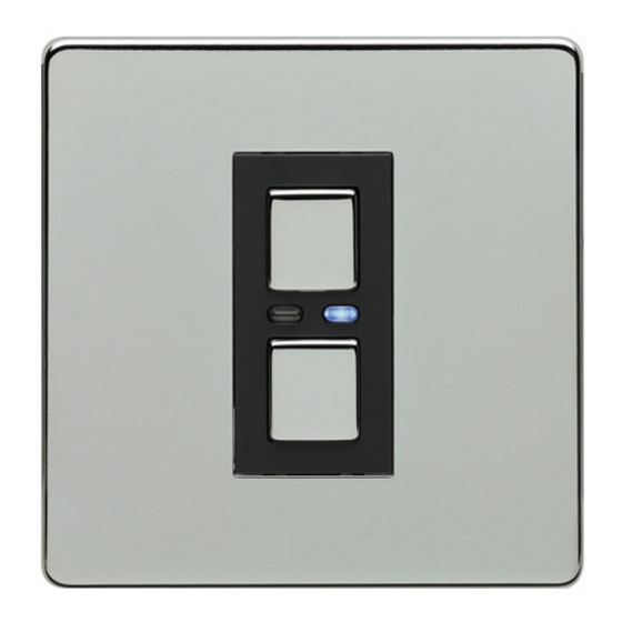
Page 4: Installation
Installation Overview Amber LED. ‘On’ button. Hold to raise light When illuminated, level. dimmer is o . Blue LED. When ‘O ’ button. illuminated, the Hold to lower light dimmer is on. level. IMPORTANT: All LightwaveRF products can be legally DIY installed in your own home;... - Page 5 Installation Live in Switched live (live out) Screw 2-Way mounting switching hole connection IMPORTANT: If conducting an insulation resistance test, all LightwaveRF products must be disconnected from the mains, or damage will occur.
- Page 6 Quick Start Guide Installation IMPORTANT: Turn o the mains electrical supply. Ensure that the wall (back) box has a minimum depth of 35mm. Remove and disconnect the existing lightswitch (if applicable). It may be useful at this point to mark out or take a photograph of the connections to the existing switch so that the correct wires can easily be transferred to the new dimmer.
- Page 7 Installation Connect the wiring as per the wiring diagram on the following page. Ensure that the terminals are properly tightened and that no bare wire is visible. Be aware that existing wiring circuits are not always correctly coloured, and that there may be other wired connections present in the back box;...
- Page 8 Installation The switched live may Signal cable connection be marked by brown/red for use with LightwaveRF tape to emphasise that 2-Way Dimmer only it is not a neutral wire. (LOW VOLTAGE: Do not connect to live mains!) Live wire In. This should be brown or red in colour.
- Page 9 Installation Replace the plate – a ‘click’ sound should be heard to signify that the plate has been correctly replaced. Important things to consider • In a multigang dimmer, to be able to operate any gang, mains electricity must always be connected to all of the dimmer terminals.
- Page 10 Installation Connecting to a 2-Way Dimmer • Any LightwaveRF dimmer switch (and any gang in a multigang dimmer) can be used in conjunction with a LightwaveRF 2-way dimmer to perform 2-way switching. For full instructions on how to install a 2-way dimmer, please consult the instruction booklet for the 2-way dimmer.
- Page 11 Installation From Lighting Circuit IMPORTANT: The signal cable input marked ‘S’ must ONLY be connected Live Switched Live to the wire running to the other dimmer NOT live mains; this will 3 - C o re cause irreparable damage. Cable Earth Live Signal Cable...
- Page 12 Compatibility & Lamps Compatibility Ensuring the compatibility of your lamps (bulbs) with LightwaveRF Dimmers will ensure that you get the best experience from your lighting setup. LightwaveRF dimmers are compatible with the following: • Selected dimmable LED lamps (see www.lightwaverf.house for further guidance and information).
- Page 13 Compatibility & Lamps Adjusting the dimming range On initial setup, LightwaveRF Dimmers are pre-programmed to allow a moderate range of dimming for any connected lamps. If desired, this range can be extended by following the instructions below. The reason for allowing modifications to the dimming range is to maximise compatibility with dimmable LED lamps (bulbs).
- Page 14 Compatibility & Lamps Tap the (top) ‘on’ button twice to enter Dimming Range Setup. The blue LED will flash to indicate that the setup menu has been accessed. The dimmer will automatically turn on at a high level of brightness. This indicates that the smallest (most stable) dimming range is currently selected.
- Page 15 Compatibility & Lamps Important things to consider • Wattage ratings for the dimmers are per gang. This means that a total load of 250W (incandescent) can be put on each circuit connected to each gang. • LightwaveRF dimmers utilise a tiny amount of power to drive the electronics that operate the RF radio and dimming components.
-
Page 16: Manual Operation
Manual Operation Manual operation Manual dimming • Tap the ‘on’ (top) button once to switch the dimmer on (blue LED indicator will illuminate). Press and hold the ‘on’ button to raise the light level. • Tap the ‘o ’ (bottom) button once to switch the dimmer o (amber LED indicator will illuminate). -
Page 17: Device Setup
6 LightwaveRF controllers in total. If you are using a smartphone/tablet/PC to control the dimmer via the Lightwave Link, this will always count as ONE controller and take up one memory slot even if you are using multiple smartphones/tablets. - Page 18 Device Setup NOTE: Linking mode lasts for 12 seconds; if no signal is received from a remote handset during this time then the dimmer will automatically exit learning mode without linking the device. If, when expecting a blue LED flash to confirm pairing, a slow amber LED flash is received instead, the dimmer switch memory is FULL and no further remotes may be linked with it unless one of the existing remotes is first unpaired (see below).
- Page 19 NOTE: Reliable range of remote operation is around 15 metres indoors and up to 100m outdoors (using a Lightwave Link). This figure may vary depending upon the environment; very thick walls, bodies of water or large metal objects may interfere with radio range.
-
Page 20: Remote Operation
Remote Operation Remote operation Dimming with the LightwaveRF App or a LightwaveRF controller • Press the ‘on’ button on the App (or other LightwaveRF controller) once to switch the dimmer (blue indicator will illuminate). Use the slider to raise or lower the light level (or press and hold the on or button on any other LightwaveRF controller). - Page 21 Remote Operation Locking the Dimmer Switch • The dimmer can be ‘locked’ so that the manual buttons will not operate it. This can be achieved using the LightwaveRF App or a ‘Socket Locker’ remote. If it is locked on, then the dimmer will not turn o manually.
- Page 22 Creative Ideas for Lightwave Dimmers 1. (Easy): Family safety Products Required: Dimmer Switch, PIR Motion Sensor Here we have a LightwaveRF Dimmer Switch paired to a PIR Motion Sensor. When somebody is detected by the sensor, it triggers the Dimmer automatically and turns the light on.
- Page 23 At the end of the evening, press the ‘all o ’ button to turn o all lights and lamps. Adding the Lightwave Link allows scene lighting to be controlled via a smartphone.
- Page 24 This setup gives you control over your devices from anywhere in the world. Here we have ceiling lights controlled by dimmers and lamps plugged into Lightwave Power Sockets or Plug-in Sockets. Via the Lightwave Link, every light can be controlled using a smartphone wherever you are. So, when you’re away on holiday, you can turn on lights to make it look like someone’s...
-
Page 25: Troubleshooting
Troubleshooting Problem: The dimmer will not operate the light and the LEDs on the dimmer do not light up. Solution: First, check that there is power to the dimmer. Make sure that the connected lamps are functioning correctly; the dimmer switch will not run unless it has a functioning lamp(s) to complete the circuit. - Page 26 The dimmer will not consistently operate remotely. Solution: The controller/Lightwave Link may be encountering interference or may be at the edge of its reliable range of operation. Ensure that there are no thick walls, large pieces of metal or bodies of water in the path of the transmission.
- Page 27 How many devices can I have on the LightwaveRF system? Each device has 6 memory slots for up 6 controllers (one of these can be the Lightwave Link allowing up to 6 smartphones to control up to 240 devices. Can I use LED bulbs?
- Page 28 FAQs Can I use non dimmable bulbs if I don't dim them? No. The bulbs must be dimmable even if they are not dimmed; the technology in the bulb must be compatible with that of the dimmer. What if I need a switch to operate on/o only? A LightwaveRF Relay in conjunction with a Wire-free Switch can be used for on/o switching in place of the dimmer (see www.lightwaverf.house).
-
Page 29: Technical Specification
Technical Specification Specification RF frequency: 433.92 MHz Input rating: 220-240V~ 50Hz. Output rating: 3W~250W max. Incandescent Load: 20W min 250W max. Back Box Depth: 35mm min. Earthing Requirement: Not essential (double insulated) Standby Energy Use: Less than 1W Wiring: Neutral wire NOT required Warranty: 2 year standard warranty... - Page 30 Version 2 Innovation Birmingham Campus Faraday Wharf Holt Street Birmingham B7 4BB 01707 386035 www.lightwaverf.com...
Need help?
Do you have a question about the JSJSLW400 and is the answer not in the manual?
Questions and answers