Table of Contents
Advertisement
Quick Links
Advertisement
Table of Contents

Summary of Contents for CoachComm Tempest NG Sideline
- Page 1 ® ® Sideline Communications System User Manual v1.2013...
- Page 2 Thank you from CoachComm! We at CoachComm want to thank you for purchasing a Tempest NG Sideline Communications System. We have made every effort to build a reliable, intuitive communication system that provides the functionality that you can count on come gameday.
- Page 3 Tempest NG 205 Technology Parkway Auburn, AL 36830 Phone: 334-321-2300 Fax: 888-329-2658 www.coachcomm.com Tempest® is a registered trademark of CoachComm, LLC. © Telex is a registered trademark of Telex Communications, Inc. ©Audiocom is a registered trademark of Bosch Security Systems, Inc.
-
Page 4: Table Of Contents
Table of Contents Introduction ............................1 A/C Power Warning .......................... 2 FCC Information ..........................2 What makes Tempest so different? ....................3 Block Diagrams ..........................5 TNG System Block Diagram ......................5 Sideline Unit Block Diagram ......................6 Pressbox Unit Block Diagram ......................7 Components ............................. - Page 5 [This page intentionally left blank]...
-
Page 6: Introduction
In 1991, CoachComm pioneered a new era in sideline communications and CoachComm’s wired systems were quickly recognized as the best in the industry. Since 1997, CoachComm, LLC has been offering wireless products to meet the communications needs of the football coaching market beginning with the UC series system. Based on the Telex® BTR/TR 600 digital radios, the UC system became the standard for sideline communications for Division 1A football as well as for most professional teams. -
Page 7: A/C Power Warning
Transmitter Module FCCID: HSW-934 FCC Regulations — CoachComm strongly urges our users of wireless products to research and where applicable pursue licensing with the Federal Communications Commission. You may wish to seek qualified legal assistance to assist you in this process. -
Page 8: What Makes Tempest So Different
UC systems have either become over crowded or are no longer a legal option. CoachComm designed the new Tempest wireless product to operate in the 2.4 GHz frequency band. This band is open for general use and does not require special licensing by the end-user. In addition, this band is specifically set-aside by the FCC for devices such as Tempest that work well together even in a crowded RF spectrum. - Page 9 [This page intentionally left blank]...
-
Page 10: Block Diagrams
Block Diagrams Block Diagrams TNG System Block Diagram Tempest NG User Manual v1.2013... -
Page 11: Sideline Unit Block Diagram
Block Diagrams Sideline Unit Block Diagram... -
Page 12: Pressbox Unit Block Diagram
Block Diagrams Pressbox Unit Block Diagram Tempest NG User Manual v1.2013... - Page 13 [This page intentionally left blank]...
-
Page 14: Components
Components Components The Sideline Unit Sub Components: 1. WAM 10 Wired Assignment Module 2. Tempest BaseStations (1, 2 or 3 units) 3. AC Power Distribution Center 4. Uninterruptible Power Supply (UPS) 5. PS 4001 AudioCom® Power Supply(s) 6. WIM 8(RD) Wired Interface Module 7. -
Page 15: The Pressbox Unit
Components The Uninterruptible Power Supply (UPS) backs up the system in the event of a power failure. The UPS will keep the system operating for approximately 20 minutes before running out of AC back up power. During the back up time, all components of the system will function from the AC on the sidelines. -
Page 16: Wim 8(Rd) Wired Interface Module
Components WIM 8(RD) Wired Interface Module Front Back 1. LCD 2. User “soft buttons” , function indicated on LCD 3. Ringdown instrument connections 4. Flexible Combine Modules — FCM (2) 5. Monitor Port 6. Test Enable Switch 7. Connections to local PS 4001 power supply(s) 8. -
Page 17: Wim 8(Rd) Integrated Dry Pair Tester (Dpt)
Components WIM 8(RD) Integrated Dry Pair Tester (DPT) The WIM 8(RD) also features an integrated dry pair tester (DPT). The DPT can only be used in systems where there are two WIM 8s. If the user had an NG sideline unit and a UC pressbox unit, the DPT will not function. When two WIM 8(RD)s are connected via dry pair, they can be put into “test mode”... -
Page 18: Wim 8(Rd) Screens
Components WIM 8(RD) Screens Menu Structure Splash Screen — This screen is displayed for a few seconds at power up of a WIM 8 or WIM 8(RD). Default Operating Screen — This screen is displayed during normal operation of the WIM 8(RD). The display shows all eight communication lines (1) and the status of both +24volt sides of those lines (2). -
Page 19: Flexible Combine Module (Fcm)
Components Flexible Combine Module (FCM) There are two (2) Flexible Isolate/Combine modules located in each WIM 8 and WIM 8(RD). This module allows for the combining or isolating of two intercom lines. For example, if you wish to have two lines of Offense, i.e. Offense 1 and Offense 2, you may wish for all coaches on the Offensive side of the ball to occasionally be in one conversation. -
Page 20: Wam 10 Wired Assignment Module
Components WAM 10 Wired Assignment Module Front Back 1. Dual Assignment Thumbwheels (1 through 10) 2. Wired back up ports, 6 pin XLR, two line (1 through 10) 3. DA-15 connections for each assignment position (not used in Tempest NG) 4. -
Page 21: The Bp 1002 / Bp 2002 Beltpacks (Audiocom® By Telex®)
Components For each wired coach, the user selects the lines that coach is to have access to via the thumbwheel switch and plugs in a wired cable and BeltPack directly under that thumbwheel switch. If you have a problem with that coach’s wireless component during the game or during setup, you may choose to put that coach on a wired set by simply plugging in a wired cable and BeltPack under that coach’s selector switch. -
Page 22: Headsets
Headsets The headsets actually worn by each user are dynamic microphone headsets. Previous models sold are the PH-100 and PH-200 and the HR-1 and HR-2. CoachComm now offers exclusively the S-Series headsets that feature our SmartBoom™ technology. SmartBoom enables a user to effortlessly mute their microphone by simply raising the boom above their brow. - Page 23 [This page intentionally left blank]...
-
Page 24: Wireless Basestation
Components Wireless BaseStation Tempest NG BaseStation Front Panel 1. Local Headset Connector — Male XLR connector. A dynamic or Electret headset microphone is automatically detected; therefore, most brands and types of headsets typically used by coaches are compatible. A headset plugged into this connector is used to monitor audio for this BaseStation. - Page 25 Components Tempest NG BaseStation Rear Panel 1. A/C Power Inlet— Power input from standard wall current or from the UPS or system power. 2. 2 Wire Intercom ‘Loop Through’ for Channels 1-4 — Male and female 15 pin ‘D sub’ connector to provide input and output to ‘Daisy Chain’...
-
Page 26: Wireless Remote Transceiver
Wireless Remote Transceiver In Tempest NG, CoachComm uses the remote transceiver mounted on the antenna mast to get the antennas higher into the air for increased performance. The positioning of the transceiver and the antennas on the transceiver are covered in the Antenna System section of this manual. - Page 27 Components [This page intentionally left blank]...
-
Page 28: Basestation Menu System
Components BaseStation Menu System Menu Structure - the BaseStation settings are accessed, viewed and changed via the BaseStation menu system. Main Status Screen —default run-time screen. The status of all five BeltPacks is shown with details about current button position, battery status, battery alert setting, RF signal strength and BeltPack name. Main Menu —... - Page 29 Components Mic Gain — adjusts the input level of the local headset microphone into the BaseStation. Note that proper Mic Gain setting on the BaseStation and each BeltPack is essential for proper system performance. When Mic Gain is set too high on any component, it can cause echo or feedback throughout the system.
- Page 30 Radio Configuration - provides access to certain radio settings such as the Network Number, Lockout Key and Transmit Power; these settings are set at the factory and should only be changed with the guidance of a CoachComm technician. Security Settings - each wireless BaseStation and corresponding BeltPacks should have matching security codes.
- Page 31 Components Wired Intercom Interface (1-7) - Each wireless BaseStation is connected to the rest of the intercom system via wired intercom connections. This menu allows the user to set levels and options for the external interfaces of the BaseStation. Intercom Levels — allows the user to control the audio levels between the BaseStation and the wired intercom system. Each Tempest BaseStation is capable of supporting eight (8) channels of intercom.
- Page 32 Components Auto-Null - Nulling is required to electronically balance an audio device, in this case a BaseStation, with a 2-wire intercom system. This procedure MUST NOT be performed while the system is in use in a game environment. All users will hear nulling-tones during the adjustment and sounds from users can interfere with the process.
- Page 33 Components Manual-Null – This is an operation that should only be used by CoachComm personnel during troubleshooting. Nulling is required to electronically balance an audio device, in this case a BaseStation, with a 2-wire intercom system. This procedure MUST NOT be performed while the system is in use in a game environment. All users will hear nulling-tones during the adjustment and sounds from users can interfere with the process.
- Page 34 Components Player Announce – The Player Announce function in the Tempest NG BaseStation is used to send a wireless BeltPack microphone signal to a dedicated external audio output. When the wireless user presses the Player button on the BeltPack, their audio is re-routed from the selected intercom channel(s) and is sent to the BaseStation rear panel Player connector. In addition, a relay closure contact is available on the RELAY connector on the back of the BaseStation.
- Page 35 Components BeltPack Settings (1-17) – The BeltPack Settings menu allows you to access and adjust settings for any BeltPack from the BaseStation. You will be prompted to select a BeltPack prior to the menu options appearing.
- Page 36 Components Talk Button – The talk button on top of the BeltPack may be set to either Latch, Momentary, or Disable. Latch means that with a quick press and release, the talk button will stay active. Momentary means that when released, the talk button always turns off.
- Page 37 Components Sidetone – This screen is used to change the sidetone for the BeltPack’s headset. Sidetone is defined as a user’s own voice folded back into the user’s headset. Volume Limit - The user can set minimum and maximum volume levels for this BeltPack. This is useful to keep a BeltPack user from accidentally turning-down their volume so low that they cannot hear or so high that the create feedback into the system.
- Page 38 Components Call Alert - Call is a non-audible signal transmitted along an intercom channel. Depending on the gear involved, the call can be interpreted by a user, by lights, tones, or in the case of the Tempest BeltPack, as a vibration. This screen allows the user to determine the action taken by the BeltPack when a call is received.
- Page 39 Components Lock Keys – To avoid accidental and undesirable setting changes occurring during use, the user may choose to lock the keys on the front of the BeltPack so that it requires a more deliberate action to make changes to the settings of the BeltPack. Lock always locks Menu, Enter, CC and Call.
- Page 40 Components Name BeltPack – Set the name of the BeltPack. This name is displayed on the front of the BeltPack and on the corresponding ‘slot’ on the BaseStation connected to that BeltPack. Base Slot Assignement – Assign BeltPack to designated Base Slot Assignment. Volume Press –...
- Page 41 Components Mode Setting - Select Normal or Shared Mode of operation. In Normal Mode, up to five BeltPacks can operate in full-time listen and talk back capabilities with one BaseStation. While in Shared Mode, there can be an unlimited number of “shared” BeltPacks operating in full-time listen and momentary talk mode on one BaseStation.
-
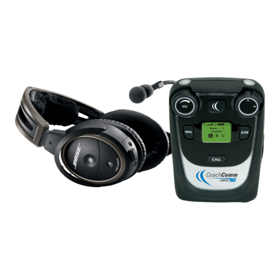
Page 42: Wireless Beltpack
Components Wireless BeltPack The Tempest NG Wireless BeltPack is to be worn by a user on the sidelines. This BeltPack communicates directly to its corresponding BaseStation. All wireless users are connected together through the wired system via the wireless BaseStations and the WIM 8. There are controls for ON/OFF/Volume and a Talk button. -
Page 43: Beltpack Battery System
5-bay charger, the sideline unit must have external AC power. The BeltPack may also be powered by three (3) alkaline AA batteries. CoachComm recommends that only major brand, standard alkaline batteries should be used for maximum reliability and effectiveness. The user should expect approximately 3-3.5 hours of operation using new alkaline AA batteries. -
Page 44: Beltpack Menu System
Components BeltPack Menu System The BeltPack settings are accessed, viewed and changed via the BeltPack menu system. Main Status Screen —default run-time screen. The status of the BeltPack is shown with details about current button position, battery status, battery alert setting, RF signal strength, BaseStation name and BeltPack name. Main Menu —... - Page 45 Components Lock Keys — To avoid accidental and undesirable setting changes occurring during use, the user may choose to lock the keys on the front of the BeltPack so that it requires a more deliberate action to make changes to the settings of the BeltPack. Lock always locks Menu, Enter, CC and Call.
- Page 46 Components Set Controls — The user may change various settings on the BeltPack including Talk Buttons, C-Button, Mic Gain, Sidetone, Volume Limit, Player announce, Call Alert, Call Button, Select Relay, Relay Button, Wireless ISO, and Volume Press. Talk Button — The talk button on top of the BeltPack may be set to either Latch, Momentary, or Disable. Latch means that with a quick press and release, the talk button will stay active.
- Page 47 Components Mic Gain — This is the input level of the headset microphone into the BeltPack. Note that proper Mic Gain setting on the BaseStation and each BeltPack is essential for proper system performance. When Mic Gain is set too high on any component, it can cause echo or feedback throughout the system.
- Page 48 Components Call Alert - Call is a non-audible signal transmitted along an intercom channel. Depending on the gear involved, the call can be interpreted by a user by lights, tones or in the case of the Tempest BeltPack, as a vibration. This screen allows the user to determine the action taken by the BeltPack when a call is received.
- Page 49 The Tech Menu consists of settings and information vital to the system’s operational status. Changes to these settings can and will affect the operational performance of the system. it is highly recommended you consult with a CoachComm technician before making adjustments in the Tech Menu.
- Page 50 BeltPack. If a change is required, the BaseStation must be changed and then all corresponding BeltPacks be “re-paired” to it for the updated settings. These should only be changed with the guidance of a CoachComm technician. Security - each wireless BaseStation and corresponding BeltPacks should have matching security codes.
-
Page 51: Antenna System
Components Antenna System The Antenna System is comprised of an antenna mast, a transceiver for each BaseStation and connecting cables. The transceivers are mounted onto the pole at the highest possible point for each unit. However, it is important that each transceiver be at a unique height on the pole. -
Page 52: Game Day Setup
Game Day Setup Game Day Setup On The Sideline Establish a firm foundation — Place the unit on the sideline as close to midfield as possible considering AC current • location, dry pair location and other sideline equipment. The unit should be placed so that if it should rain, the unit will not become flooded. -
Page 53: In The Pressbox
Game Day Setup In The Pressbox Establish a Good Location — The Pressbox Unit should be placed so that it is on a firm footing. If possible, place the unit • far enough away from the coaching area so that drinks and food, or other damaging elements, will not effect its operation. The location should be near the dry pair connections and near an AC wall outlet. -
Page 54: Wireless Component Set Up And Integration
Game Day Setup Wireless Component Set Up and Integration The wireless portion of the Tempest NG Series is an add on to the wired system. If the wired system is not set up properly or if there is a problem with the dry pair or any aspect of the wired system, the wireless portion may not work correctly. Each BaseStation and its corresponding five (5) BeltPacks must be tested thoroughly to insure proper operation. - Page 55 Understanding Link Quality The Link Quality (LQ) is a numeric value that provides a real-time metric on the quality of communication between the radio in the BaseStation or Remote Transceiver and the radio in the BeltPack. The LQ serves as a diagnostic tool for proper system operation and troubleshooting BeltPacks.
- Page 56 Game Day Setup 4. Power up Base A and observe the LQ at the corresponding BeltPacks. The LQ should read “99” at start-up. a. If they do not read “99” , power OFF the BaseStation and be sure no other 900 MHz devices are operating near your system.
- Page 57 Bad Sideline or Press Box panel (WIM/ Isolate to Sideline or Press Box by WAM) disconnecting dry pair; remove outside components from system; if still present, contact CoachComm Support Charger Red LEDs Possible heat issue (safety mechanism) - heat indoors...
- Page 58 Game Day Setup [This page intentionally left blank] Tempest NG User Manual v1.2013...
-
Page 59: Glossary
Glossary Glossary Dry Pair A twisted pair of wires, typically connecting between the pressbox and the sidelines. For the Telex® AudioCom® system operating from power on one end only, this wire should be 26 gauge or better. Sidetone The user’s own voice folded back into the user’s ear. This adjustment allows for a user to hear more or less of his own voice in his headset. -
Page 60: Update The Firmware (With Codeupdater)
Appendix Appendix A Update the Firmware (with CodeUpdater) Tempest NG firmware updates are released periodically, and equipment should be updated to maximize optimal system performance. Staying up to date with the latest firmware ensures that your system is equipped with the newest features and enhancements that Tempest has to offer. -
Page 61: Tempest Ng Specifications
Appendix Appendix B Tempest NG Specifications System RF Frequency ....................2400 to 2483.5 MHz RF Scheme ....................FHSS with TDMA Effective Radiated Power ................100 mW (using 2dBi antenna) Receiver Sensitivity ...................-90 dBm for 10^(-5) BER Radio Certification ..................FCC Part 15.247, ETS 300.328, Canadian RSS-210, license free Transmission Range ..................1000’... - Page 62 Remote Antenna Transceiver Maximum Distance, Base to Transceiver ..........1,500 ft. Connection to BaseStation ...............CAT-5 standard wiring BaseStations Supported Per Transceiver ..........1 Antenna Connector Type ................RP-TNC Supplied Antenna ..................Whip Omni-directional antenna Dimensions with Antennas (inches) ............12 h x 3.7 w x 1.7 d Weight (with antennas) ................13.6 oz Specifications subject to change without notice.
-
Page 63: Tempest Ng900 Specifications
Appendix C Tempest NG900 Specifications System RF Frequency ....................902-928 MHz RF Scheme ....................FHSS with TDMA Effective Radiated Power ................250 mW (using 2dBi antenna) Receiver Sensitivity ...................-100 dBm for 10^(-5) BER Radio Certification ..................FCC Part 15.247, Canadian RSS-210, license free Transmission Range ..................1000’ under ideal conditions (500 ft - 900 ft typical) Audio Dynamic Range ................>94 dB Audio Frequency Response ..............300 Hz –... - Page 64 Notes Tempest NG User Manual v1.2013...
Need help?
Do you have a question about the Tempest NG Sideline and is the answer not in the manual?
Questions and answers