Advertisement
INSTALLATION AND MAINTENANCE INSTRUCTIONS
with Dry Nitrogen Holding Charge
These instructions must be read and understood completely before attempting installation.
The equipment covered in this manual is to be installed by trained and experienced service and
installation technicians. Improper installation, modification, service, or use can cause electrical
shock, fire, explosion, or other conditions which may cause personal injury, death, or property
damage. Use appropriate safety gear including safety glasses and gloves when installing this
equipment.
Risk of electrical shock. Disconnect all remote power
supplies before installing or servicing any portion of the
system. Failure to disconnect power supplies can result
in property damage, personal injury, or death.
Installation and servicing of air conditioning equipment
can be hazardous due to internal refrigerant pressure
and live electrical components. Only trained and
qualified service personnel should install or service
this equipment. Installation and service performed by
unqualified persons can result in property damage,
personal injury, or death.
Sharp metal edges can cause injury. When installing
the unit, use care to avoid sharp edges.
506875-01
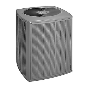
2SHP13 Series
Split System Heat Pump
WARNING
WARNING
WARNING
WARNING
INSTALLATION .....................................................2
START-UP .......................................................... 11
OPERATION ...................................................... 15
MAINTENANCE ................................................. 17
HOMEOWNER INFORMATION ........................ 18
WIRING DIAGRAM ............................................ 21
WARRANTY ...................................................... 23
*P506875-01*
Issue 1139
TABLE OF CONTENTS
(P) 506875-01
Page 1 of 23
Advertisement

Related Manuals for Lennox 2SHP13 Series


Summary of Contents for Lennox 2SHP13 Series
-
Page 1: Table Of Contents
INSTALLATION AND MAINTENANCE INSTRUCTIONS 2SHP13 Series with Dry Nitrogen Holding Charge Split System Heat Pump These instructions must be read and understood completely before attempting installation. WARNING The equipment covered in this manual is to be installed by trained and experienced service and installation technicians. -
Page 2: Installation
INSTALLATION Location of Unit Outdoor units operate under a wide range of weather General conditions; therefore, multiple factors must be considered This heat pump, which will also be referred to in this when positioning the unit. The unit must be positioned to instruction as the outdoor unit, uses HCFC-22 give adequate clearances for sufficient airflow and refrigerant. - Page 3 • Locate unit away from overhanging roof lines which Wind Barrier Construction would allow water or ice to drop on, or in front of, coil or into unit. Slab Mounting When installing a unit at grade level, install on slab high enough above grade so that water from higher ground will not collect around the unit (see Figure 2).
- Page 4 3. Install room thermostat on an inside wall that is not Refrigerant Piping subject to drafts, direct sunshine, or other heat Field refrigerant piping consists of liquid and suction lines sources. from the outdoor unit (sweat connections) to the indoor coil (flare or sweat connections).
- Page 5 Installing Refrigerant Line Brazing Connection Procedure During the installation of an air conditioning system, it is 1. Cut ends of refrigerant lines square (free from nicks important to properly isolate the refrigerant line to prevent or dents). Debur the ends. The pipe must remain unnecessary vibration.
- Page 6 Refrigerant Line Sets: Installing Horizontal Ru To hang line set from joist or rafter, use either metal strapping material Wire Tie or anchored heavy nylon wire ties. (around vapor line only) 8’ Strapping Material Floor Joist or (around vapor line only) Roof Rafter Tape or Wire Tie 8’...
- Page 7 Refrigerant Line Sets: Installing Vertical Runs (new construction shown) IMPORTANT: Refrigerant lines must not contact wall. Outside Wall Vapor Line Liquid Line NOTE: Similar installation practices should be used if line set is to be Wood Block installed on exterior of outside wall. Between Studs Wire Tie Inside Wall...
- Page 8 Expansion Valve Systems Expansion valves equipped with Chatleff-type fittings are Service Valve available from the manufacturer. See Table 4 for proper TXV for each unit. TXV Data Table 4 To install an expansion valve (see Figure 9 on page 7): 1.
- Page 9 Leak Testing To Close Liquid or Suction Line Service Valve: After the line set has been connected to the indoor and 1. Remove the stem cap with an adjustable wrench. outdoor units, the line set connections and indoor unit must be checked for leaks. 2.
- Page 10 as any gas that will not condense under temperatures 9. Reconnect the manifold gauge to the vacuum pump, and pressures present during operation of an air turn the pump on, and continue to evacuate the system conditioning system. Noncondensables and water vapor until 500 microns is maintained within a 20-minute combine with refrigerant to produce substances that period after shutting off the vacuum pump and closing...
-
Page 11: Start-Up
START-UP IMPORTANT CAUTION Mineral oils are not compatible with R-410A. If oil must be added, it must be a polyolester oil. If unit is equipped with a crankcase heater, it should be energized 24 hours before unit start-up to prevent compressor damage as a result of slugging. -
Page 12: Cooling Cycle
Cooling Cycle Use gauge ports on suction line valve and liquid line valve for evacuation refrigerant lines and indoor coil. Use suction gauge to measure suction pressure during charging. Figure 12 2. At the same time, record the liquid line pressure Charge Using Weigh-In Method (Fixed Orifice/TXV reading. - Page 13 Superheat Values for Subcooling Values for TXV Systems Fixed Orifice Systems (80°DB/67°WB Return Air) Table 6 3. Use a temperature/pressure chart for HCFC-22 to determine the saturation temperature for the suction line pressure reading. 4. Subtract the saturation temperature (according to the chart) from the suction line temperature to determine Table 7 the superheat.
- Page 14 Normal Operating Pressures L - Liquid S - Suction Values provided above are typical pressures. Indoor unit matchup, indoor air quality equipment, and indoor load will cause pressures to vary. Table 8 Approach Values for TXV Systems Approach value is the liquid line temperature minus the outdoor ambient temperature (±1°...
-
Page 15: Operation
OPERATION Emergency heat is usually used during an outdoor shutdown, but it should also be used following a power outage if power has been off for over an hour and the Outdoor unit and indoor blower cycle on demand from outdoor temperature is below 50°F. - Page 16 The control provides automatic switching from normal During a single demand cycle, the defrost control will lock heating operation to defrost mode and back. During the out the unit after the fifth time that the circuit is interrupted compressor cycle (call for defrost), the control by any pressure switch wired to the control board.
-
Page 17: Maintenance
MAINTENANCE Defrost Control Board Diagnostic LEDs WARNING Mode Green LED Red LED No Power Before performing maintenance operations on system, to Board turn the electric power to unit OFF at disconnect Normal Operation/ Simultaneous Slow Flash switch(es). Unit may have multiple power supplies. Power to Board Electrical shock could cause personal injury or death. -
Page 18: Homeowner Information
HOMEOWNER INFORMATION The outdoor coil may require frequent cleaning, depending on environmental conditions. Clean the outdoor coil with In order to ensure peak performance, your system must be an unpressurized water hose to remove surface properly maintained. Clogged filters and blocked airflow contaminants and debris. - Page 19 Thermostat Operation Preservice Check Though your thermostat may vary somewhat from the If your system fails to operate, check the following before description below, its operation will be similar. calling for service: Temperature Setting Levers Check to see that all electrical disconnect switches are Most heat hump thermostats have two temperature selector levers: one for heating and one for cooling.
- Page 20 Start-Up and Performance Checklist Job Name _______________________________ Job No. ________________ Date ______________ Job Location _____________________________ City ___________________ State ______________ Installer _________________________________ City ___________________ State ______________ Unit Model No. ______________ Serial No. ___________________ Service Technician ________________________________________ Nameplate Voltage ______________ Rated Load Ampacity ________ Compressor _______________ Outdoor Fan ___________________ Maximum Fuse or Circuit Breaker ________________________...
-
Page 21: Wiring Diagram
Single Phase Wiring Diagram p/N 463330-002 Figure 14 506875-01 Issue 1139 Page 21 of 23... - Page 22 Figure 15 Page 22 of 23 Issue 1139 506875-01...
-
Page 23: Warranty
Should such exclusion or limitation of the listed below: warranty be unenforceable, such implied warranties are in any event Lennox Industries Inc. Allied Air Enterprises limited to to a period of one (1) year. Liability for incidental and conse- P.O.
Need help?
Do you have a question about the 2SHP13 Series and is the answer not in the manual?
Questions and answers