Table of Contents
Advertisement
Quick Links
Advertisement
Table of Contents

Summary of Contents for CCTVdirect Cobra Elite 960H
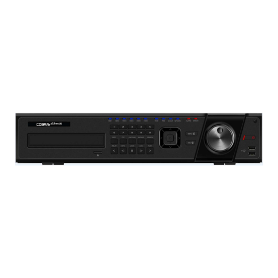
- Page 1 Elite 960H Ver 2.0...
- Page 2 FCC Compliance Statement Cobra Elite 960H Model Name: This device complies with Part 15 of the FCC Rules. Operation is Subject to the following two conductions: (1) this device may not cause harmful interference, and (2) this device must accept any interference received, including interference that may cause undesired operations.
-
Page 3: Table Of Contents
....3- 1 Deluxe Series Front Panel Button ............12 3- 2 COBRA ELITE 960H Series Remote Controller ......... 13 3- 3 Mouse ....................14 3- 4 Jog/ Shuttle ..................14 Chapter 4 4 4 4 . DVR Operation Setup Chapter . - Page 4 5-7-1 Search Mode .................... 29 5-7-2 Year/Month/Day Selection ................29 5-7-3 Time Index ....................29 5-7-4 Event ...................... 30 5-7-5 Multi-Channel Search ................. 30 5-7-6 Multi-Time Search ..................30 5-7-7 Multi-Day Search ..................30 5-7-8 List All ..................... 31 5- 8 POS Search ..................31 5-8-1...
- Page 5 6-3-4 Alarm ...................... 47 6-3-5 Duration ....................47 6-3-6 Log ......................47 6- 4 Schedule ................... 47 6-4-1 Schedule Setup..................47 6- 5 Storage ..................... 48 6-5-1 Max. Recording Days ................. 48 6-5-2 HDD Overwrite..................48 6-5-3 Local Storage Management ................. 48 6- 6...
- Page 6 [Figure 2-1. COBRA ELITE 960H-16CH Basic Connection and Device Connection] ......9 [Figure 2-7. COBRA ELITE 960H-16CH Terminal Block and Description] ........11 [Figure 4-11. Menu Window]....................17 [Figure 5-12. Recording Status Window] ................19 [Figure 5-13. Login Window] ....................20 [Figure 5-14.
-
Page 7: Introduction
Chapter 1. Introduction 1-1 960H Series Major Features Line Up 960H DVR Model Name COBRA ELITE 960H-16 Embedded Linux - Built in flash memory Access Front button, Mouse, Remote Controller, Network, Key controller System Live monitoring, Recording, Playback, Hexaplex Backup, Network, Setup Upgrade USB2.0 Memory stick, Network... -
Page 8: 1-2 Components
Full HD, XGA SDTV(720x480/576) Mode 16/9/4/1/SEQ - LIVE, 16/9/4/1 - P.B ★ 2 RS485 - Terminal Block PTZ / Keyboard External Interface ★ RS232C - Terminal Block ATM / POS Primary 6 HDD Storage External 2 eSATA 1 DVD Jog-shuttle ★... -
Page 9: 1-3 Product Introduction
1-3 Product Introduction 960H real-time recording 16Ch audio recording 1Ch spot output Various video output port (HDMI, VGA, BNC) Various video output mode (Full HD, WSXGA+, SXGA, SDTV) 6 HDD bay (COBRA ELITE 960HModel) Jog-shuttle 8Ch POS/ATM interface Pre-alarm recording Auto e-mailing notification max. -
Page 10: Installation And Connection
Power supply Opening Power 90 ~ 250V, 50/60Hz, 80 Watts (H-model series) AC Inlet AUDIO IN Audio Input Connection LOOP OUT Video Signal loop-back Output Connection 2-2 Installation and Connection [Figure 2-1. COBRA ELITE 960H-16CH Basic Connection and Device Connection]... -
Page 11: 2-2-1Basic Connection
Sensor / Relay / POS Rear Panel Terminal Block Keyboard controller Rear Panel Terminal Block 1) SPOT Monitor Connect Spot Monitor to the rear SPOT terminal. 960H series supports 1ea SPOT terminals. 2) Audio Input/Output COBRA ELITE 960H-16CH supports 16ea audio inputs. - Page 12 3) Terminal Block [Figure 2-2. COBRA ELITE 960H-16CH Terminal Block and Description] The terminal blocks in the rear of the product are for the connection of PTZ / Sensor / Relay / POS Connection. The number of the terminal block may be different depending on the model.
-
Page 13: Ion And Setup Tools
(3) POS Connection ⑤ Connect the POS device. ⑥ Connect the POS to Terminal Block POS. The external alarm device may require the power supply depending on its type. Be cautious. Chapter 3. Operation and Setup Tools 960H Series can be controlled easily by using the front panel buttons, front panel, remote controller, jogshuttle and mouse. -
Page 14: 3-2Cobra Elite 960H Series Remote Controller
3-2COBRA ELITE 960H Series Remote Controller A) Basic Control Button Turn the system power POWER ON or OFF. Record all channels or stops recording RECORD all channels. NUMBER Input of numeric data. Set up the remote controller ID. B) System Operation and Setup Button... -
Page 15: 3-3 Mouse
※ ※ ※ ※ Setting up the remote controller ID Example) When the remote controller ID is set to 1 Press the {ID} button, enter {0} and {1}, and press the {ID} button again. To control all DVRs with the different ID, set the remote controller ID to 999. 3-3... - Page 16 ※ Step 1 1) Using a screw driver, unscrew and take off the top case of the product. 1) Normal termination of the system and fully unplugged power code are required before conducting HDD installation. 2) After installing HDD, Do not connect to power supply with the top case opened.
- Page 17 ※ Step 4) Align screw holes and screw and fix HDD onto the bottom HDD bay①. 5) Align screw holes and screw and fix HDD onto the top HDD bay② 6) By reversing Step 2, combine both top② and bottom① HDD bay with the body.
-
Page 18: 4-2 Power On
4-2 Power ON. ① Check the Power, COBRA ELITE 960HModel (90 ~ 250V, 50/60Hz) and connect the power. ② Once Power cable is connected (found in Rear Side), booting will be enabled. . ③ After booting is finished, the live screen and channel indication / clock are shown. ④... -
Page 19: 4-5 Date/Time Setup
4-5 Date/Time Setup ① Select {Menu} {Setup} {Time}. ② Configure [Time Sever]/[Date and Time]/[Standard Time Zone]. 4-6 Camera / TV Setup ① Select {Menu} {Setup} {Camera} {Adjust}. ② Set up for [Brightness/Contrast/Color/Hue/Camera Adjustment/TV OUT Adjustment] are available. 4-7 Display Setting and Other Setup ①... -
Page 20: Chap Chapter Chap Ter 5 5 5 5 . System Operation Ter . System Operation . System Operation
Chapter 5. System Operation 5-1 Real Time Monitoring Mode and Icon After booting is finished, Audio/Recording Status/Channel Title/Connection Status/Time/HDD Status are displayed as shown below. [Figure 5-4. Recording Status Window] ※ ※ ※ ※ Recording Event / Recording Mode Icon ※ ※ ※ ※ Motion Detection Recording Sensor Recording Recording... -
Page 21: 5-2 System Login
※ ※ ※ ※ Control Bar ※ ※ ※ ※ ① ① ① ① Full Screen ② ② ② ② 4 Channel Screen ③ ③ ③ ③ 8 Channel Screen ④ ④ ④ ④ 16 Channel Screen ⑤ ⑤ ⑤ ⑤ ZOOM function ⑥... -
Page 22: 5-2-3 Logout
5-2-3 Logout After logging out, the user cannot use {Menu}. ① On the real-time monitoring screen, select {Menu} {Logout}. 5-3 Monitoring 960H Model Series features powerful monitoring functions as shown below. 1 / 4 / 9 / 16 Division Mode and Auto Sequence Mode Channel Grouping 960H Model (4) Spot 960H Model 1/4/9/16 Multi spot... -
Page 23: 5-3-2 Channel Grouping
※ The user can view an image on full screen by double-clicking a desired channel in the 4/9/16 Sub- Screen mode. Double-click any part of the screen to return to the previous mode. ※ ※ ※ ※ Auto Sequence Auto Sequence is to rotate images at an interval of the certain time in 1/4/9 Basic Division. Auto Sequence is not available in the Basic 16 Division mode. -
Page 24: 5-3-4 Menu In Monitoring Mode
The priority for Spot is Manual Spot > Event Spot > Sequence Spot. ① Manual Spot The user can designate a spot channel manually. COBRA ELITE 960HModel 16CH supports 4ea Spot channels. [Figure 5-9. Spot] ② Move to {Menu} {Miscellaneous} {Misc. -
Page 25: 5-3-6 Screen Control By Using Ptz
[Figure 5-10. Zoom Control Screen] ⑥ In case of the mouse, move the pointer to an area to be zoomed in the zoom control screen and double-click on it. ⑦ Then, it zooms in 3 levels; Normal, x4, x16. Those 3 levels can be controlled by the wheel of the mouse. - Page 26 ※ Baud rate can be selected at 2400/4800/9600/19200/38400. ※ Duration can be selected at 5/10/15/20/5-60(User setting) seconds. ※ Tour consists of Tour 1/ Tour 2 and each tour can be set with 8 Preset. ※ COBRA ELITE 960HModel series supports 28 protocols for PTZ control. For supported protocols, refer to APPENDIX.
-
Page 27: 5-4 System Information And Screen Setup Change
5-4 System Information and Screen Setup Change 5-4-1 System Information [Figure 5-14. Product Information Window] 5-4-2 Screen Brightness/Contrast/Color/Saturation/Sharpen/Camera Adjustment Select {Adjust}, then it becomes the 1 channel mode and a window pops up as shown below. [Figure 5-15. Screen Setup Window] Moving the camera, down, right, or left excessively may cause black or gray areas to appear on the screen. -
Page 28: 5-4-3 Display Setting
5-4-3 Display Setting Camera Title On/Off, Control Bar On/Off, Button Sound On/Off, Border Line Draw/Width/Color, Sequence Duration 1-10seconds. After selecting Display Setting, it becomes the 1 channel mode and a menu pops up as shown below. [Figure 5-16. Display Setting Window] 5-4-4... -
Page 29: 5-5 Control
5-5 Control In the real-time monitoring, move to {Menu} {Miscellaneous} {Misc. Control}. [Figure 5-18. Audio] [Figure 5-19 . Relay] [Figure 5-20. Text] ① Move to the Audio tab and select the channel to be activated or Mute. 960H-model 16CH support 16 channel audios, 960H-model 8CH model support 8 channel audios and 960H-model 4CH model support 4 channel audios. -
Page 30: 5-6-2 Playback Menu
5-6-2 Playback Menu (1) Calendar Search Calendar Search allows the user search and playback by [Year/Month/Day/Hour/Minute],[Multi-Channel/Multi- Time/Multi-Day]and [Motion/Sensor/Audio/Pattern]. (2) Go To The Last The user can search and playback the last recorded data by Multi-Channel Mode. (3) Go To The First The user can search and playback the first recorded data by Multi-Channel Mode. -
Page 31: 5-7-4 Event
5-7-4 Event Event is to search the data by the events. Select [All/Motion/Sensor/Audio/Pattern/Text]. 5-7-5 Multi-Channel Search The Multi-Channel Search is to play recorded images of the different channel over a certain designated time. ① Select the desired Year/Month in the calendar window. ②... -
Page 32: 5-7-8List All
5-7-8List All To check Time index in order of time line. [Figure 5-23. Time Index] 5-8 POS Search 5-8-1POS Search Mode On the real-time monitoring screen, select {Menu} {Search} {POS Search} and then a searching window pops up as shown below. 5-8-2Year/Month/Day/Text/Time Selection Please select date/time, Time index, Text 1~3, and select the start time within the channel.. -
Page 33: 5-9 Playback
5-9 Playback [Figure 5-25. Playback Screen] ※ There are five routes to play the recorded image. Playback in the Calendar Search Select {Playback} in {Menu} {Search} {Calendar Search} {Search}. Playback in the Go To The Last Select {Menu} {Search} {Go to The Last}. Playback in the Go To The First Select {Menu} {Search}... -
Page 34: 5-9-2 Smart Search
Description of the Search Buttons Button Name Features Channel Mode Change Switch the channel mode. Zoom Mode Switch to the Zoom mode. Press one time - Playback forward (ⅹ1) Press two times - Fast forward (ⅹ2) Press three times - Fast forward (ⅹ4) Press four times - Fast forward (ⅹ8) Forward Play / Fast Forward Press five times - Fast forward (ⅹ16) -
Page 35: 5-9-3 Pos Search
① Move to the Smart Search and select the desired channel. ② After shifting to the 1 channel mode, select areas to be smart searched. [Figure 5-28. Smart Search Area Designation] ③ The 14 * 15 pixel mosaic mode appears. In the beginning, all pixels are selected. Designate an a rea by left-click and drag the pixel mosaic pointer(deep yellow). -
Page 36: 5-9-7 Multi Channel
5-9-7 MULTI CHANNEL Multi-Channel Search is to play recorded images of the different channel over a certain designated time. 5-9-8 Panorama Play Panorama Play is to play recorded images of the certain channel frame by frame. Panorama Play can be viewed at 16 frame / 8 frame / 4 frame / 1 frame. -
Page 37: 5-10-1 Log Type
[Figure 5-32. Log View] 5-10-1 Log Type Logs related to power ON/OFF, file copy/backup failure, setup start/end, General playback, and other basic system operations Logs related to the recording including motion detection and sensor Recording Event detection, Audio detection Logs related to network operations including network login, network Network logout, and network live Logs related to system operation failures including signal loss and... -
Page 38: 5-11 Recording
[Figure 5-33 . Move to the log list of the certain time zone in Log View] Time Changed Log Data View The stored data folder is created each time the user changes the time. A blue triangular icon is displayed at a date in the calendar window that time changes are made. Otherwise, a red triangular icon is displayed at an unchanged date. -
Page 39: 5-12 Backup
5-12 Backup In order to backup the data, make sure to check that either internal or external storage devices (CD, DVD or HDD) supports USB 2.0 is connected. For supported external devices, refer to Appendix. The user can back up data in the real-time monitoring, search, log, or the playback mode. -
Page 40: 5-12-5 Common Backup Procedure
5-12-5 Common Backup Procedure [Figure 5-34. Backup Window] ① [ Figure 5 [ Figure 5- - - - 34] shows the initial backup window menus. [ Figure 5 [ Figure 5 ② A list of the devices that can be selected is outputted with simple information of the currently selec ted devices ③... -
Page 41: 5-14 Log Backup
[Figure 5-35. Backup and Sub-menu Setup Backup] ① For the Setup Backup, a device for backup must be connected. ② Move to {Menu} {Backup} {Setup Backup} and a window shown below appears. The setup is copied by the name shown below. [Figure 5-36. -
Page 42: 5-15 Capture
5-15 Capture The Capture function lets the user create a JPG file in the real-time monitoring, playback, search, or log mode and back up the image data. ① To back up the currently displayed image, select {Menu} {Backup} {Capture} in real-time monitoring, Playback and Log mode. -
Page 43: Chapter 6 6 6 6 . Setup Chapter . Setup . Setup
Chapter 6. Setup 6-1 Time ※ ※ ※ ※ Function Description 1. Time Synchronization 1) Synchronization with the NTP server The time is synchronized once every hour with the NTP Server. A. Automatic Setup The nearest server from the user’s zone will be selected for connection. If the connection fails, the next nearest server will be chosen. -
Page 44: 6-1-2 Date And Time
6-1-2 Date and Time (1) Date and Time Only available when Time Server is off. The system date and time format is Year/Month/Day Hour/Minute/Second. ① By using the arrow keys and the Select button, move the focus onto the desired field; Year/Month/ Day Hour/Minute/Second and press the Select button. -
Page 45: 6-2 Camera
6-2 Camera [Figure 6-40. Setup / Camera Menu] 6-2-1 Camera ① Connection Used to set whether to connect or disconnect each camera channel. ※ When the camera channel is set to disconnected, the video contents will not be displayed even if the camera is actually connected. ②... -
Page 46: 6-2-5 Relay
[Figure 6-41. Motion Area Setup] ① Select Motion Area of each channel. ② It becomes the 1 channel division mode and rectangular boxes appear where motions occur. Drag the yellow pixel cursor by using the mouse or the front button/remote controller and select pixels w here motion detection doesn’t applied. -
Page 47: 6-3-1 Schedule Selection (Schedule1 ~ Schedule4)
6-3-1 Schedule Selection (Schedule1 ~ Schedule4) ① Each channel can be scheduled in 4 different schedules. This schedule can be set as the recording schedule and each time can be 4 different schedules. 6-3-2 Event This is to set the events On/Off of Motion / Sensor / Sound / Text Input / Text Search. Recording Description Type... -
Page 48: 6-3-4 Alarm
6-3-4 Alarm ※ This function is used to generate alarms through the Buzzer / PTZ Preset / e-mail / Relay / Spot / Popup in case of an event. PTZ preset can be configured between 1-16. ※ Popup function is to inform event occurrence to the user through a warning window in the real-time monitoring mode. -
Page 49: 6-5 Storage
6-5 Storage [Figure 6-44. Storage Window (Local)] In the Storage menu, To apply the new setting, save the new setting after changing the setting. Reset: Initialize the menu to the basic setting. 6-5-1 Max. Recording Days This is to limit the recording days. You can set None/1day/7days/30days/User setting(1-31). 6-5-2... - Page 50 In {New}, At least, one storage shall be selected as a dedicated storage. Otherwise, the data cannot be stored in the real time. ① iSCSI iSCSI HDD Setting. (Please refer to ‘6-6-6’ for more details) (2) Composition of the local storage device ※...
-
Page 51: 6-6 Network
(1) How to changed FAULT HDD ① Check Faulty HDD number ② Turn OFF unit by power button. ③ Detach cover of DVR ④ Find the faulty HDD by number printed on mainboard ⑤ Detach the faulty HDD ⑥ Attach new HDD. ⑦... -
Page 52: 6-6-3Port
① Select On/Off of DDNS or a domain name to use by using arrow keys and the selection button. ② In case of DDNS On, enter the host name and save it then, the registration procedure of the host name proceeds automatically. You can enter the host name with 4-20 letters. ③... - Page 53 [Figure 6-47. Setup Network Ethernet Window] [Figure 6-48. Setup Network E-Mail Window1] This is to set automatic E-mail transmission service when an event occurs. To use the e-mail function, {E-mail} in {Menu} {Setup} {System} {9. Alarm} or {E-mail} in {Menu} {Setup} {Action} { Alarm} need to be configured.
-
Page 54: 6-6-5 Bandwidth
② Relay SMTP is set on ‘Gmail’ as default, but when ‘Default’ (in menu tab) is selected, this will changed to dvr@cctvuser.com. ③ Receiver Email can be set up to 5 users (emails). ④ Email Interval settings are as follows [5 sec / 1 min / 3 min / 5 min /10 min]. 6-6-5... -
Page 55: 6-7 System
[Figure 6-51. Setup iSCSI Window2] ④ {Storage} -> {iSCSI} Tab, the registered iSCSI Storage will be displaced, and can be used for ‘Recording’ purposes only. ⑤ When the ‘Status’ is shown as ‘Unusable’, this means that another DVR is currently using the storage. -
Page 56: 6-7-1 Dvr Name
1. DVR Name Used to name the DVR device. 2. ID For Remote Controller Used to name the remote controller for running the system. 3. ID For Key Controller Unique system controller number setting. 4. User Registration Used to register, add, or delete users. 5. -
Page 57: 6-7-4 User Registration
6-7-4 User Registration ※ ※ ※ ※ Add, edit, or delete the users who will operate the system and give authorities to users as shown below. System Access Authorization Network Live View the real-time images upon network access. Playback View the recorded images. Copy (download) Copy and download files. -
Page 58: 6-7-7 Factory Default
② Read the information and select {Yes} to start the upgrade gradually. Select {No} to return to the {System} mode. ③ After the upgrade is completed, the system reboots. ④ Move to {Menu} {Miscellaneous} {DVR Information} {3. Software Version} to check the version. -
Page 59: 6-7-12 Language
The Automatic Menu Exit is not used. ※ The user can exit the menu by pressing the [ESC] button in the System menu. If there is no input from the front button, remote controller, or mouse, the 1/2/3 MIN system will shift to the real-time monitoring mode. The user can enter the time directly. -
Page 60: Appendix
APPENDIX A/P/P/E/N/D/I/X Recommended PTZ Camera Protocol Vendor Model Protocol ULTRA_7 A.D. SENSORMATIC ULTRA_8 CHOU COHU3925 COHU DRX-500 Dongyang Dongyang DY-255 DYNACOLOR DSCP DSCP EYE VIEW EYE VIEW EYE VIEW FINE SYSTEM CRR-1600i/s CRR-1600i/s GE_KARATEL CYBERSCAN_1 HITRON FASTRAX2 FASTRAX2 HONEYWELL SCANDOME2 HSDN-251 LG_MULTIX, LG_OLD...