Table of Contents

Subscribe to Our Youtube Channel
Summary of Contents for Apollo 8
- Page 1 H I G H - R E S O L U T I O N I N T E R F A C E with Realtime UAD Processing Apollo 8 Hardware Manual Manual Version 150702 Customer Service & Technical Support:...
-
Page 2: A Letter From Bill Putnam Jr
Apollo into your creative process, we hope that the excitement and pride that we’ve built into it comes through. We believe Apollo will earn its way into your creative work- flow by providing stunning fidelity, great ease-of-use, and rock-solid reliability for years to come. -
Page 3: Table Of Contents
Click any section or page number to jump directly to that page. A Letter from Bill Putnam Jr..............2 Introduction ..................4 What is Apollo 8? ....................4 Apollo 8 Features ....................6 About Apollo 8 Documentation ................8 Web Documentation ................... 9 Technical Support .................... -
Page 4: Introduction
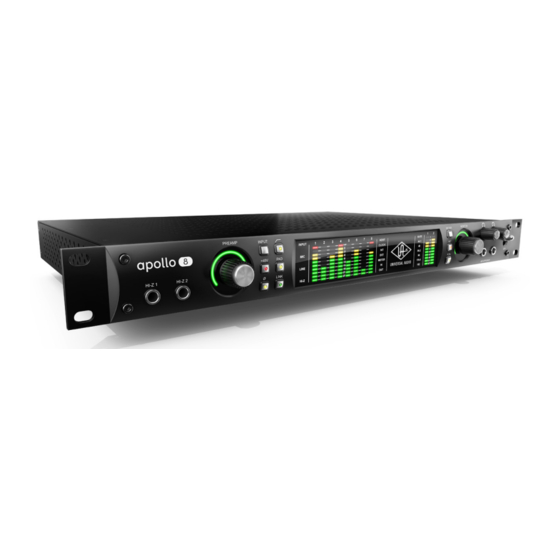
What is Apollo 8? Thunderbolt Audio Interface with UAD-2 Processing Apollo 8 is an elegant update to one of the world’s most popular professional audio in- terfaces — delivering enhanced sound with the tone, feel, and flow of analog recording. - Page 5 Thanks to Apollo Expanded software, users of Thunderbolt-equipped Apollo Twin, Apollo 8, Apollo 8p, and Apollo 16 audio interfaces can combine up to four Apollos and six total UAD-2 devices — adding I/O and DSP as their studio grows. Apollo Expanded also provides seamless integration with previous generation Apollos over Thunderbolt.
-
Page 6: Apollo 8 Features
• 18 x 24 Thunderbolt 2 audio interface (Thunderbolt 1 compatible) for Mac with powerful Console 2.0 software control • Cascade up to 4 Apollo interfaces and 6 UAD devices total over Thunderbolt • Convenient front panel monitoring functions including Alt Speakers, and assign- able Alt 2, Dim, or Mono •... - Page 7 Console application: • Analog-style control interface for realtime monitoring and tracking • Enables Realtime UAD Processing with UAD plug-ins • Remote control of Apollo 8 features and functionality • Virtual I/O for routing DAW tracks through Console Console Recall plug-in: •...
-
Page 8: About Apollo 8 Documentation
Apollo software fea- tures for all Apollo models using the Console application, Console Settings window, and Console Recall plug-in. Refer to the Apollo Software Manual to learn how to operate the software tools and integrate Apollo’s functionality into the DAW environment. -
Page 9: Web Documentation
Apollo Support Page The latest technical information for Apollo is posted on the Universal Audio website. The Apollo Thunderbolt support page contains updated, late-breaking information that is not available in other publications. Please visit this page for the latest news: •... -
Page 10: Technical Support
Technical Support Universal Audio provides free customer support to all registered Apollo users. Support specialists are available to assist you via email and telephone during normal business hours, which are from 9 AM to 5 PM, Monday through Friday, Pacific Standard Time. -
Page 11: Front Panel
Front Panel This section describes the features and functionality of all controls and visual elements on the Apollo 8 front panel. Note: All front panel functions (except the METER switch, headphone volume knobs, and power switch) can be controlled remotely with the included Console software application. - Page 12 • When the Gain knob (#2) is rotated, the ring flashes to indicate that no gain ad- justment is occurring • If a Unison plug-in is in the channel’s dedicated Unison insert in Console, the Unison plug-in is bypassed Apollo 8 Hardware Manual Front Panel...
- Page 13 Note: If the ring is at maximum and flashes when the Preamp knob is rotated, the channel’s LINE input is selected and LINE INPUT GAIN is set to BYPASS. See Line Input Gain Bypass for additional details. Apollo 8 Hardware Manual Front Panel...
- Page 14 Depending on the current configuration of the hardware and software, there may be a delay when changing the +48V state to minimize the clicks/pops that are inherent when engaging phantom power. The +48V LED will blink rapidly during any delay. Apollo 8 Hardware Manual Front Panel...
- Page 15 The currently selected channel increments when the Preamp knob (#2) is pressed. Note: The numbers for channels 5 – 8 do not illuminate, as they cannot be se- lected for front panel control adjustments.
- Page 16 The 10-segment LED channel meters display the input or output signal peak levels for analog channels 1 – 8. Input or output metering is selected with the METER switch (#19), and the input/output state is shown by the METER indicators (#15).
- Page 17 When set to internal clock, the INT indicator is illuminated white. External Clock Apollo 8 can use an external clock from the Word Clock, S/PDIF, or ADAT inputs. The EXT indicator has two possible states: White – When set to external clock and a valid clock signal is detected at the specified port, the EXT indicator is illuminated white and Apollo 8 is synchronized to the external clock source.
- Page 18 Apollo Software Manual. Tip: ALT 2 outputs (line outputs 3 & 4) can be selected with the FCN switch (#21, when configured in Console Settings) or in the Monitor column within the Console application. Apollo 8 Hardware Manual Front Panel...
- Page 19 Control Room strip within the Console application. The Monitor Level Indicator (#23) flashes when DIM is active. Note: When more than one Apollo interface is connected in a multi-unit configura- tion, the FCN switch is operable on the designated monitor unit only.
- Page 20 Console Settings window (when ALT COUNT is a non-zero value), the ALT monitor outputs are also muted by this control. When the monitor outs are muted, the Monitor Level Indicator ring (#23) is red. Note: Monitor Mute does not mute the headphone outputs. Apollo 8 Hardware Manual Front Panel...
- Page 21 Console or by assigning mix buses from a DAW to the headphone outputs via the device drivers. (26) Power Switch This switch applies power to Apollo 8. When the unit is powered on, the Universal Audio logo (#16) is illuminated. The external power supply must be properly connected for this switch to function.
-
Page 22: Rear Panel
Apollo 8 rear panel (digital portion) (27) Power Input The included external power supply connects to this 4-pin locking XLR jack. Apollo 8 requires 12 volts DC power and draws approximately 50 Watts. To eliminate risk of circuit damage, connect only the factory-supplied power supply. Use the Power switch on the front panel to power the unit on and off. -
Page 23: Digital I/O
1 – 2 3 – 4 Note: The ADAT ports use TOSLINK JIS F05 optical connectors. Some devices use this type of connector for optical S/PDIF connections. However, Apollo 8’s ADAT ports do not support the S/PDIF protocol. Apollo 8 Hardware Manual... - Page 24 For example, if Apollo 8 is the last “slave” unit at the end of a clock chain (when Apollo 8’s word clock out port is not used), termination should be active.
- Page 25 Console Settings window. (32) Thunderbolt Ports Apollo 8 has two Thunderbolt 2 ports. One port is used to connect Apollo 8 to a Thunderbolt 1 or Thunderbolt 2 port on the host computer. Thunderbolt peripheral devices may be serially connected (daisy-chained) to the second Thunderbolt port.
-
Page 26: Analog I/O
Settings window. ALT Outputs 1 – 4 Apollo 8 features ALT (alternate) monitoring capabilities. ALT monitoring can be used to control up to two alternate pairs of monitor speakers. When ALT monitoring is enabled, the output level and muting of line outputs 1 & 2 (ALT 1) and 3 &... - Page 27 Unbalanced ¼” TS cables can also be used. Line Inputs 5 – 8 can be individually configured to use –10 dBV or +4 dBu reference levels. This option is set in the channel input strips within the Console application.
- Page 28 +4 dBu. When routed into the preamps, gain for line inputs 1 – 4 is continuously variable with up to 65 dB of available gain. Note: For related information, see Line Input Gain Bypass. Apollo 8 Hardware Manual Rear Panel...
-
Page 29: Installation & Configuration
UAD software the first time the device is connected. System Configuration Complete details about setting up the Apollo 8 system, including how to integrate with a DAW and related information, are included in the Apollo Software Manual. -
Page 30: Interconnections
Interconnections Installation Notes • Apollo 8 may get hot during normal operation if it doesn’t receive adequate airflow circulation around its chassis vents. For optimum results when mounting Apollo 8 in a rack, leaving at least one empty rack space above the unit to allow adequate airflow for cooling is recommended. -
Page 31: Basic Setup
Basic Setup This diagram illustrates a simple Apollo 8 setup that could be used by an individual musician/engineer for recording and mixing. It shows an electric guitar connected to the Hi-Z input of channel 1 and a microphone connected to the XLR input of channel 2 so they can both be recorded simultaneously. -
Page 32: Typical Setup
Typical Setup This diagram illustrates an Apollo 8 setup that could be used to record two musicians simultaneously. In this setup, only analog devices are connected; digital I/O is not used. The example shows an electric guitar and electric bass connected to the Hi-Z inputs. -
Page 33: Advanced Setup
• Four additional mic preamps from UA’s 4-710d are routed into Apollo 8 via ADAT Lightpipe • Apollo 8 is the master clock device; the 4-710d clock source is set to exter- nal word clock and the 4-710d Termination switch is engaged (alternately, the... -
Page 34: Apollo Expanded: Multi-Unit Wiring
• Apollo device ordering and Thunderbolt ports used (second port on Apollo vs. second port on computer, placement within daisy chain, etc) is not important. • In this wiring example diagram, the Apollo 8 in the center is the designated monitor (master) unit. Connect speakers (including ALT speakers) and any cue outputs to the monitor unit only. -
Page 35: Specifications
Simultaneous D/A conversion 14 channels Analog Round-Trip Latency 1.1 milliseconds @ 96 kHz sample rate Analog Round-Trip Latency with up to four serial 1.1 milliseconds @ 96 kHz sample rate UAD plug-ins via Console application (continued) Apollo 8 Hardware Manual Specifications... - Page 36 60 dB (10’ cable) Input Impedance 10K Ohms Gain Range +10 dB to +65 dB (Line Input Gain = ON) Reference Level +4 dBu (Line Input Gain = BYPASS) Maximum Input Level +20.2 dBu (continued) Apollo 8 Hardware Manual Specifications...
- Page 37 ANALOG I/O (continued) Line Inputs 5 – 8 Connector Type ¼” Female TRS Balanced Dynamic Range 120 dB (A–weighting) Signal-to-Noise Ratio 120 dB (A–weighting) Total Harmonic Distortion + Noise –110 dBFS Common-Mode Rejection Ratio (CMRR) 60 dB (10’ cable) Input Impedance...
- Page 38 44.1, 48, 88.2, 96, 176.4, 192 Channel Assignments @ 44.1 kHz, 48 kHz Port 1 = Channels 1 – 8, Port 2 = 1 – 8 (mirrored) Channel Assignments @ 88.2 kHz, 96 kHz Port 1 = Channels 1 – 4, Port 2 = Channels 5 – 8 Channel Assignments @ 176.4 kHz, 192 kHz...
-
Page 39: Block Diagram
Block Diagram Apollo 8 Hardware Manual Block Diagram... -
Page 40: Troubleshooting
Troubleshooting If Apollo 8 isn’t behaving as expected, here are some common troubleshooting items to confirm. If you are still experiencing issues after performing these checks, contact Technical Support. SYMPTOM ITEMS TO CHECK Unit won’t power on • Confirm power supply connections at power supply input and back of unit •... -
Page 41: Notices
The unit has been dropped, or the enclosure damaged. Servicing – The user should not attempt to service the unit beyond that described in the operating instructions. All other servicing should be referred to qualified service personnel. Apollo 8 Hardware Manual Notices... -
Page 42: Warranty
You may also have other rights which vary by state or country. Maintenance Apollo 8 does not contain a fuse or any other user-replaceable parts. The unit is inter- nally calibrated at the factory. No internal user adjustments are available. Repair Service... - Page 43 Trademarks Universal Audio, the Universal Audio “diamond” logo, Apollo, Apollo Twin, Apollo 16, Unison technology, UAD, UAD Series, UAD-1, UAD-2, UAD-2 Satellite, Powered Plug-Ins, 1176LN, 1176SE, Teletronix, LA-2A, LA-3A, LA-610, LA-610MkII, 2-1176,...
- Page 44 Universal Audio, Inc. 4585 Scotts Valley Drive Scotts Valley, CA 95066 USA Customer Service & Technical Support: USA Toll-Free: +1-877-698-2834 International: +1-831-440-1176 www.uaudio.com...
Need help?
Do you have a question about the 8 and is the answer not in the manual?
Questions and answers