Table of Contents

Summary of Contents for Apollo 16
- Page 1 H I G H - R E S O L U T I O N I N T E R F A C E with Realtime UAD Processing Apollo 16 Hardware Manual Manual Version 150702 Customer Service & Technical Support:...
-
Page 2: A Letter From Bill Putnam Jr
So as you begin to incorporate Apollo into your creative process, we hope that the excitement and pride that we’ve built into it comes through. We believe Apollo will earn its way into your creative workflow by providing stunning fidelity, great ease-of-use, and rock-solid reliability for years to come. -
Page 3: Table Of Contents
Table Of Contents A Letter from Bill Putnam Jr..........................ii Introduction................................4 What is Apollo 16? ............................4 Apollo 16 Features ............................5 About Realtime UAD Processing ........................7 Combining with other UAD-2 devices ......................7 About Apollo 16 Documentation ........................8 Technical Support ............................ -
Page 4: Introduction
Apollo 16 uses FireWire or Thunderbolt for computer connectivity. FireWire 800 doubles the performance of FireWire 400 and ensures the ability to use all of Apollo 16’s I/O as well as its DSP processing. Thunderbolt is a high-speed data transmission protocol that provides faster throughput than FireWire. The Thunderbolt Option Card (not included) can be easily installed in Apollo 16’s expansion bay allowing Apollo 16 to connect with... -
Page 5: Apollo 16 Features
• Sample rates up to 192 kHz at 24-bit word length • 16 x 18 simultaneous analog input/output channels: • 16 channels of analog-to-digital conversion via line inputs on dual DB25 connectors • 18 channels of digital-to-analog conversion: • 16 line outputs via dual DB25 connectors •... - Page 6 Software • Console application: • Enables Realtime UAD Processing • Controls Apollo 16’s DSP mixer for realtime monitoring and/or tracking with UAD plug-ins • Four independent stereo Cue buses • Two independent stereo Auxiliary buses • Remote control of Apollo 16 features and functionality •...
-
Page 7: About Realtime Uad Processing
Powered Plug-Ins loaded within the DAW operate like other (non-UAD) plug-ins, except the processing occurs on the Apollo 16 DSP instead of the host computer’s processor. In this scenario, UAD plug-ins are subject to the latencies incurred by I/O buffering. -
Page 8: About Apollo 16 Documentation
The Apollo Software Manual is the companion guide to the Apollo Hardware Manuals. It contains detailed information about how to configure and control the software features of all Apollo models using the Console ap- plication and Console Recall plug-in. Refer to the Apollo Software Manual to learn how to operate the software tools and integrate Apollo’s audio interface functionality into the DAW environment. -
Page 9: Technical Support
Thunderbolt Option Card All user documentation for Apollo 16’s Thunderbolt Option Card is located on the Thunderbolt Support Page on our website (there is no separate manual). Please review the information on the page carefully before installing or using the device: •... -
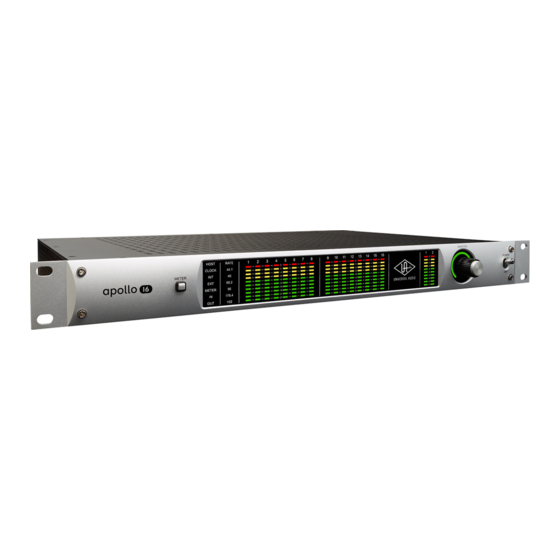
Page 10: Front Panel
INT indicator is illuminated. When Apollo 16 is set to use an external clock as the master clock source and a valid clock signal is detected at the specified port, the EXT indicator is illuminated and white. - Page 11 The Apollo 16 sample rate is indicated in this area. The active sample rate is illuminated. (4) Channel Meters The sixteen 10-segment LED meters display the signal peak levels for analog channels 1 – 16. The Channel Meters can display either the input or output levels, as determined by the METER button (1).
- Page 12 Note: This feature indicates relative levels only and is not calibrated to any specific dB values. (9) Power Switch This switch applies power to Apollo 16. When the unit is powered on, the Universal Audio logo is illuminated. The external power supply must be properly connected for this switch to function.
-
Page 13: Rear Panel
Rear Panel This section describes the features and functionality of all connectors and controls on the Apollo 16 rear panel. Analog I/O AES/EBU IN MON OUT (R) 2 MON OUT (L) 1 LINE OUT 9-16 LINE IN 9-16 PUSH LINE OUT 1-8 LINE IN 1-8 (1) Monitor Outputs 1 &... -
Page 14: Digital I/O
Console Settings window within the Console application. When Apollo 16 is set to use external word clock as its clock, Apollo 16 is a word clock slave. If the incoming external word clock is within ±0.5% of a supported sample rate (44.1 kHz, 48 kHz, 88.2 kHz, 96 kHz, 176.4 kHz, 192 kHz), Word Clock Out will mirror Word Clock In with a slight phase delay (about 40ns). - Page 15 Apollo 16’s termination switch should only be engaged when Apollo 16 is set to sync to external word clock and it is the last device at the receiving end of a word clock cable. For example, if Apollo 16 is the last “slave” unit at the end of a clock chain (when Apollo 16’s word clock out port is not used), termination should be active.
-
Page 16: Host I/O
When Apollo 16 is properly connected and configured, the HOST indicator (#2 on front panel) is il- luminated. Apollo 16 has two FireWire 800 ports. Only one port is used to connect to the host computer; the second port can be used for daisy-chaining multiple FireWire devices such as external FireWire hard drives. For more FireWire information and recommended interconnections, see ““FireWire Basics”... -
Page 17: Installation & Configuration
For complete details about how to operate Console, refer to the Apollo Software Manual. Multi-Unit Cascading When more I/O and/or DSP is needed, two Apollo 16’s can be cascaded together via FireWire in a multiple-unit configuration. For examples, see “Interconnections” beginning on page 18. -
Page 18: Interconnections
Interconnections Installation Notes 1. Apollo 16 may get hot during normal operation if it doesn’t receive adequate airflow circulation around its chassis vents. For optimum results when mounting Apollo 16 in a rack, we recommend leaving at least one empty rack space above the unit to allow adequate airflow for cooling. - Page 19 Thunderbolt Setup This diagram illustrates how Apollo 16 can be connected to a host computer with the Thunderbolt Option Card. Key points for this example: • The Thunderbolt Option Card (not included) must be installed in Apollo 16 to connect via Thunderbolt •...
- Page 20 Multi-Unit Cascading Setup – FireWire Host Connection This diagram illustrates how two Apollo 16 units are connected together into an aggregated interface for 32 simultaneous analog inputs and 32 simultaneous analog outputs using FireWire 800 to connect to the host computer.
- Page 21 • The computer and all Apollo units must be connected to the same Thunderbolt bus. • The Apollo device ordering and the Thunderbolt ports used (second port on Apollo vs. second port on computer, placement in daisy chain, etc) is not important.
-
Page 22: Firewire Basics
Some FireWire devices can be “bus powered” which means the device derives its operating electricity from the FireWire bus itself without a power supply of its own. Apollo 16 cannot be bus powered and it does not supply bus power from its FireWire ports to other devices. - Page 23 FireWire ports or a peripheral FireWire repeater, or any combination of the two in a “tree chain” topology. Apollo 16 can function as a FireWire repeater, by using the unused port on the unit to connect other FireWire devices. Note that Apollo 16 does not supply FireWire bus power to downstream devices.
- Page 24 6-pin FireWire cable or adapter. However in this scenario any 800 megabit-capable devices on the bus (includ- ing Apollo 16) will operate at a maximum of 400 megabits because FireWire bandwidth cannot exceed the maximum bus speed of the host computer.
- Page 25 FireWire with Thunderbolt When Apollo 16 is connected to the computer via the Thunderbolt Option Card, both of Apollo 16’s FireWire ports remain active and they can be connected to FireWire peripheral devices such as hard drives. For an illustration of this configuration, see “Thunderbolt Setup”...
-
Page 26: Digital Clocking Basics
Clock drift affects long-term synchronization, like sound to picture, and can introduce slight pitch variations in the audio. Usually however, the drift is so slow that these pitch variations are only tiny fractions of a cent, and thus unnoticeable. Apollo 16 Hardware Manual Digital Clocking Basics... - Page 27 The best they can do is avoid making it any worse, but this is hardly worth the cost: It’s much better (and less expensive) to use a good converter like Apollo than it is to try and fix a bad one with an expensive master clock.
-
Page 28: Specifications
1.1 milliseconds @ 96 kHz sample rate Analog Round-Trip Latency with up to four serial 1.1 milliseconds @ 96 kHz sample rate UAD Powered Plug-Ins via Console application ANALOG I/O Analog Inputs 1 – 16 Dynamic Range 119 dB (A–weighting) Signal-to-Noise Ratio 119 dB (A–weighting) - Page 29 ANALOG I/O Analog Outputs 1 – 16 Dynamic Range 118.5 dB (A–weighting) Signal-to-Noise Ratio 118.2 dB (A–weighting) Total Harmonic Distortion + Noise -107.5 dB @ -1 dBFS Connector Type Two Female DB25, Tascam wiring Monitor Outputs 1 – 2 Dynamic Range 115 dB (A–weighting)
- Page 30 Shipping Weight (with box & accessories) 18 pounds Weight (bare unit) 8.7 pounds Package Contents Apollo 16 Audio Interface External Power Supply Apollo Hardware Manual 15’ FireWire 800 cable (2) IEC AC Power Cables (USA & Europe) Set of (4) Rack-Mount Screws...
-
Page 31: Hardware Block Diagram
Hardware Block Diagram Apollo 16 Hardware Manual Hardware Block Diagram... -
Page 32: Db25 Wiring
Tascam pinouts also used with Digidesign and Avid products. DB25 Connector Pin Numbers The pin numbers for female DB25 connectors are shown in the diagram below. When facing the Apollo 16 rear panel, pin 1 is the upper rightmost pin. -
Page 33: Troubleshooting
Troubleshooting If Apollo 16 isn’t behaving the way you expect it to, here are some common troubleshooting items to confirm. If you are still experiencing issues after performing these checks, contact technical support (see “Technical Sup- port” on page 9). -
Page 34: Notices
The unit has been dropped, or the enclosure damaged. 11. Servicing - The user should not attempt to service the unit beyond that described in the operating instructions. All other servicing should be referred to qualified service personnel. Apollo 16 Hardware Manual Notices... -
Page 35: Warranty
You may also have other rights which vary by state or country. Maintenance Apollo 16 does not contain a fuse or any other user-replaceable parts. The unit is internally calibrated at the factory. No internal user adjustments are available. - Page 36 Trademarks Universal Audio, the Universal Audio “diamond” logo, Apollo, Apollo Twin, Apollo 16, Unison technology, UAD, UAD Series, UAD-1, UAD-2, UAD-2 Satellite, Powered Plug-Ins, 1176LN, 1176SE, Teletronix, LA-2A, LA-3A, LA-610, LA-610MkII, 2-1176, 2-610, 6176, 710 Twin-Finity, 2192, 4-710d, Cambridge EQ, DreamVerb, Plate 140, Precision Limiter, RealVerb Pro, Precision Buss Compressor, Precision De-Esser, Precision Maximizer, and “Analog Ears | Digital Minds,”...
-
Page 37: Index
Host I/O 16 Analog Inputs 28 Analog I/O 13 ANALOG I/O 28 Inputs 13 Analog Outputs 29 Interconnections 18 Apollo 16 Documentation 8 Introduction 4 Apollo Software Manual 8 I/O Complement 28 Audio Interface 5 Jitter 26 Block Diagram 31... - Page 38 Typical Setup 18 UAD-2 5 UAD Powered Plug-Ins 7 UAD System Manual 8 Weight 30 Welcome ii Word Clock 29 Word Clock In 14 Word Clock Out 14 Word Clock Termination Switch 15 XLR 13 Apollo 16 Hardware Manual Index...
- Page 39 Universal Audio, Inc. 4585 Scotts Valley Dr Scotts Valley CA 95066 USA Customer Service & Technical Support: USA Toll-Free: +1-877-698-2834 International: +1-831-440-1176 www.uaudio.com...
Need help?
Do you have a question about the 16 and is the answer not in the manual?
Questions and answers