Advertisement
Quick Links
Advertisement

Summary of Contents for Atlantic HAL 1200
- Page 1 USER'S MANUAL 1200W AUTOMATIC LINEAR AMPLIFIER Model: HAL1200 Atlantic...
- Page 2 A - Introduction Thank you for purchasing the HAL 1200 Atlantic. (Automatic Transistorized Linear Amplifier No Tune Inside Computerized). This compact and lightweight desktop HF + 50MHz linear power amplifier has a maximum input power of 2.4 KW. Our solid-state broadband power amp technology makes it the smallest and lightest in the industry.
- Page 3 B-7 The amplifier has fast acting sophisticated protection circuits controlled by the latest microprocessor technology. Please note, however, any such actions that cause the same fault to occur repeatedly, will lead to failure of the valuable final power MOSFET transistors. B-8 Before checking into the amplifier, always disconnect the mains power supply, with the power disconnected, press the power switch to "POWER"...
- Page 4 C - Features C-1 Our solid-state broadband design engineers worked to make the HAL 1200 Atlantic, the lightest and most compact 1200 W HF amplifier in the industry. C-2 The amplifier is equipped with a newly developed band decoder. The amplifier’s decoder whit the microprocessor, on detecting RF input, changes bands automatically without any external connection, or as the data signal is received from the connection of the associated HF transceiver’s...
- Page 5 D - Specifications Frequency : 1.8 ~ 54 MHz all amateur bands including WARC bands Automatic Band Change (only PTT/TXGND Signal), or with dedicated connection for the most common Transceivers Yaesu, Kenwood, ICOM, Elecraft . Mode : SSB, CW, RTTY RF Drive : 20 ~ 45 W (30W typ.) (automatic selection: NO ALC)
- Page 6 PROTECTIONS: - Over Drive - Output Power Limiter - High SWR (SWR > 2:1) - Over Temperature - Fault of PA Fuses - In the event of erroneus Band Change Input/Output Connectors: UHF SO-239 Teflon AC Power : AC 100 ~ 260 V / 16 ~ 10 A max. Dimension : 261 x 334 x 153 mm (W x D x H) Weight...
- Page 7 E - Front Panel Description ③ ④ ⑤ ⑥ ⑦ ⑧ ② ① ① POWER Main power switch to turn AC power ON (I) and OFF (O). Display lights when turned on. ② STBY STAND-BY/OPERATE key and annunciator Yellow LED. At STAND-BY mode, the Yellow LED is ON, RF signal pass through.
- Page 8 ⑥ OK OK Key; in operating mode, and in the event of an alarm Warning or Protection, confirms the reading of the message displayed , Resetting the alarm status and turns OFF the Red LED indicator ; in menu mode, confirm your selection.
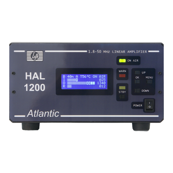
- Page 9 F - Display Description ① ② ③ ④ ⑤ ⑥ ⑦ ⑧ ⑨ ① B Selected band and operational. ② Type of change automatic band selected and active : A= Internal automatic band decoder, Y= Yaesu Band Data, K= Kenwood CAT RS232 or IF232, I= Icom CI-V, E= Elecraft Band Out . S=Semi-automatic with the help of the inner decoder bandwidth.
- Page 10 G - Rear Panel Description ① ② ③ ④ ⑤ ⑥ ⑦ ⑧ ⑨ ① an with safety grill. ② RF OUTPUT RF Output Connector. Connect the coax cable to the antenna. ③ RF INPUT RF Input Connector. Connect the coax jumper cable from the transceiver.
- Page 11 H - Inside Top View ① ② ③ ④ Control Unit Backup Battery . ( 15 Years of life ). ① ② Control Unit Fuse. (250 V/1,6 A glass fuse 5 x 20). Power Amplifier Module Fuse #1 . (250 V/16A glass fuse 5x20 or 6.3x32). ③...
- Page 12 I - Connection ANTENNA COAX GROUND MAINS COAX 100-260 VAC TX GND / SEND / REMOTE BAND DATA / CAT BAND DATA CABLE TRANSCEIVER...
- Page 13 L – Setup Connect AC cord, turn ON the POWER (AC mains) switch, display lights. Runs the Soft-Start and the Self-Test, then display the operation screen; push MENU key, you see the following menu : Selected with the UP / DOWN keys, moving the pointer arrow on the required function and confirm with OK key.
- Page 14 ELECRAFT : Automatic Band Change with the connection to BAND OUT Elecraft. SEMIAUT : Semiautomatic band change with the help of the internal decoder, only the connection to the TX GND is required. (from StandBy mode), status STBY, send a carrier, (CW, FM, ..) with a minimum of 10W power, runs the Change Band, status changes in SET B, switch to Operate,...
- Page 15 Selection; QUIT : Return to previos screen. Selection; RESET : Select this option if and only if you are having malfunctions of the software screening program. All Data and Settings will be lost. The tracks stored in the case of diagnostic assistance will no longer be available.
- Page 16 M - Operation M - 1 Connect AC cord and coax cables as illustrated in section Connection. Connect the cable from TX GND to TX GND or the remote terminals of transceiver, where it is marked “SEND” or “REMOTE”. These terminal pins are shorted to ground when the transceiver is in TX/ON AIR mode.
- Page 17 M – 6 With the driving power from 45W to 65W, are automatically inserted in the input some attenuators, to prevent distortion of the amplification, for this reason, in some cases, the output power can be lower than with an optimal drive. This case is indicated by an "H"...
- Page 18 N - Protection & Safety HAL1200 Atlantic is equipped with various protection circuits, handled by the 16-bit microprocessor . The microprocessor controls three ( 3 ) levels of security and protection. First level (min) : the anomaly is handled automatically and in some cases is reported.
- Page 19 Protection Message Event Signaling Reset & Level Displayed Condition Out of HAM OUTBAND / Out of HAM band WARN lights Push key OK Bands (L3) DATA CAT ERR OUT in line “B” Push key STBY AUTOBAND OUTBAND / BandData Cable WARN lights Push key OK Data Error (L3)
- Page 20 O - Band Data Cable Connection This section describes the various types of connection cables that allow the Data communication with the modern transceivers of the houses, YAESU, KENWOOD, ICOM, ELECRAFT. Thus, the Automatic Band Change, takes place already currently receiving, (RX).
- Page 23 Hardware & Software Via XXIX Maggio, 229 – 20025 LEGNANO (Italy) Tel. +39 0331.50.59.40 e-mail : info@gbhs.it website: http://www.gbhs.it...
Need help?
Do you have a question about the HAL 1200 and is the answer not in the manual?
Questions and answers