Table of Contents
Advertisement
Advertisement
Table of Contents
Troubleshooting

Subscribe to Our Youtube Channel
Summary of Contents for Matsutec HP-33A
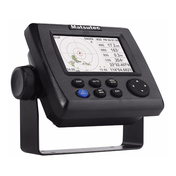
- Page 1 CLASS B AIS TRANSPONDER WITH GPS NAVIGATOR...
-
Page 2: Safety Instructions
Continued use of the equipment can cause fire or electrical shock.Contact a Matsutec agent for service. Use the proper fuse. Use of a wrong fuse can damage the equipment or cause fire. - Page 3 NOTICE WARNING Observe the following compass safe Do not open the cover unless totally distances to prevent interference to a familiar with electrical circuits and magnetic compass: service manual. Improper handling can result in electrical Standard Steering shock. compass compass Turn off the power at the switchboard Display 0.
-
Page 4: Table Of Contents
FOREWORD........................v SYSTEM OVERVIEW....................vii SYSTEM CONFIGURATION ..................viii 1. OPERATIONAL OVERVIEW.................. 1-1 1.1 Controls ........................1-1 1.2 How to Turn Power On/Off ..................1-2 1.3 How to Adjust LCD and Key Panel Brilliance ............1-3 1.4 Display Modes ......................1-3 1.5 Menu Overview......................1-10 1.6 How to Enter the MOB Mark.................. - Page 5 3.5 How to Change Track Color..................3-4 3.6 How to Erase Track....................3-4 3.6.1 How to erase track by color................3-4 3.6.2 How to erase all tracks .................. 3-5 4. WAYPOINTS......................4-1 4.1 How to Enter Waypoints..................... 4-1 4.1.1 How to enter a waypoint with the cursor............4-1 4.1.2 How to enter a waypoint at own boat position..........4-1 4.1.3 How to enter a waypoint through the list............
- Page 6 ....................... 9-1 Maintenance ......................9-2 Troubleshooting Displaying the Message Board .................. 9-3 Diagnostics ......................... 9-3 ......................9-4 Clearing Data 10. INSTALLATION ....................10-1 10.1 Equipment Lists ...................... 10-1 10.2 Installation of Receiver Unit..................10-1 10.2.1 ................10-1 Installation consideration 10.2.2 ............
-
Page 7: Foreword
A Word to the Owner of the HP-33A Congratulations on your choice of the HP-33A class B AIS transponder. For over 10 years Matsutec® has enjoyed an enviable reputation for innovative and dependable marine electronics is furthered by our extensive global network of agents and dealers. - Page 9 Not all ships carry AIS The Officer of the Watch (OOW) should always be aware that other ships, and in particular leisure craft, fishing boats and warships, and some coastal shore stations (including Vessel Traffic Service centers) might not be fitted with AIS. The OOW should also be aware that AIS fitted on other ships as a mandatory carriage requirement might be switched off by the master if its use might compromise the security of the vessel.
- Page 10 viii...
- Page 13 Your unit has nine display modes: AIS Radar Display, AIS Lists Display, Plotter Display, Highway Display, Steering Display, Nav Data Display, Satellite Monitor Display, User Display 1 and User Display 2. Press the DISP key to select a display mode. Each time the key is pressed, the display mode changes in the sequence shown below.
- Page 14 AIS Radar Display The AIS Radar display shows the location of other AIS-equipped targets relative to your own boat. AIS Lists Display The AIS Lists display shows the lists of target, danger, watch, alarm and message.
- Page 15 The Plotter display shows waypoints, routes, own boat track and AIS targets.
- Page 20 1-10...
- Page 21 1-11...
-
Page 22: Ais
2. AIS Symbols 2. .1 Target type Symbol Description Base Station AtoN SART Class A ships EPIRB Class B ships or not identified 2. .2 Target status Symbol Description Gray Lost target Not identified (Name not received ) Yellow Identified, Name received Green Watch target Pink... -
Page 23: Target Dynamic
The “Lost target” disappears from the display 6 minutes and 40 seconds after it was declared as a “Lost target”. Target declared as “lost target” after a period of time shown in the table below: Target’s status Except Class B Class B Vessel is at anchor, moored and moving less than 3 knots 18 min. -
Page 24: Ais Alarm
AIS Alarm Type Condition Collision Alarm When a target’s CPA and TCPA are lower than set MOB Alarm MOB devices received SART Alarm SART received EPIRB Alarm EPIRB received MOB Test Alarm MOB test received SART Test Alarm SART test received EPIRB Test Alarm EPIRB Test After a specified period of time (show in Table 1) passed since... -
Page 25: Class A Vessel
2. .1 Class A Vessel... -
Page 26: Class B Vessel
2. .2 Class B Vessel 2. .3 Base Station... -
Page 27: Aton
2. .4 AtoN... -
Page 28: Sar
2. .5 SAR 2. .6 Others This is for the targets not identified or MOB, SART, EPIRB, etc. -
Page 29: Ais Radar Display
2. AIS Radar Display The AIS Radar display shows the location of other AIS-equipped vessels and shore stations relative to your own vessel within the current range. The position and course of your ship are also displayed in the center. 2. -
Page 30: Direction Up
2. .2 Direction Up You can change the radar display direction, North up or Course up. Press the GOTO key in the radar display to alternate North up or course up. 1. When “N-UP” is displayed, the top of the plotter display represents north. 2. -
Page 31: Target Lists
2. .1 Target Lists The target list display shows all AIS targets being detected by the transponder, including their range and bearing information. The AIS target data is sorted by the distance from your vessel, and the closest target is located on the top of the list. Press ▲... -
Page 32: Watch Lists
2. .3 Watch Lists The watch list screen shows the watch target you set. Watch target is set for special care, such as for friend ships, fishing net buoys, etc. You can switch on or off the lost alarm, position alarm, etc. of the watch targets. Up to 100 AIS targets can be set as your watch targets. - Page 33 2. .3.1 Add Watch AIS Use ▲ or ▲ key to select the first line [New], then press ENT key to add a new watch target. Input the MMSI of the target that you want to watch. Input the comment for better explication. •...
- Page 34 2. .3.2 Watch Target Menu Use ▲ or ▼ key to select a watch target, then press ENT key to get a pop-up menu for further operation. • Detail Get detailed information of the watch target. • Edit Watch Edit the watch items, such as MMSI, to watch another target, or switch on/off watch alarms, or modify the position, or position range.
-
Page 35: Alarm Lists
2.5.4 Alarm Lists Show the alarms by sort of start time. 2.5.5 Message Lists Show the messages by sort of receive time. 2-14... -
Page 36: Plotter Display
2.6 Plotter Display Show the AIS targets in the plotter display. 2.6.1 Select Target Info Use arrow key ▲,▼,◀ ,▶ to move the cursor to the desired target, a small window will pop up to show the basic information about the target. To get detailed information of the target, press ENT key. -
Page 37: Ais Config
2.7 AIS Config AIS configurations are done through the menu. Below is a quick introduction to how to select a menu and change menu settings. If you get lost in operation, press the MENU/ZOOM key to return to the main menu. 1. -
Page 38: Setting Name
2. Press ▲or ▼ key to input the specific 9-digit MMSI code. 3. Push ◀ or ▶ key to move the cursor forward or backward. 4. Push MENU/ZOOM key to cancel the modification, or press ENT to confirm the modification. Notes: 1. -
Page 39: Gps Antenna Position
Vessels anti-pollution Law enforcement vessels Medical transports Ships according to Resolution 18 Passenger ships Cargo Ships Tanker 2.7.4 GPS antenna position Press ▲or ▼ key to select “A,” “B,” “C” or “D.” • A : Bow to Antenna, Between 0 and 511 meters (0 and 1676.5 feet) •... -
Page 40: Ais External Alarm Buzz Control
• CPA : default 6 km • TCPA : default 6 min Push MENU/ZOOM key to cancel or press ENT key to save the configuration. 2.7.6 AIS External Alarm Buzz Control Choose to switch on/off the external alarm buzz. 2.7.7 Setting Channel TX Choose to switch on/off the channel TX. -
Page 41: Own Dynamic
2. .2 Own Dyanmic This screen shows your dynamic vessel information such as Latitude and Longitude data, SOG, COG, GPS receiver type, UTC date and time, etc. 2-20... -
Page 42: Plotter Display Overview
PLOTTER DISPLAY OVERVIEW How to Select the Display Range You can change the display range on the plotter and highway displays. The horizontal range in the plotter display is available among 0.02, 0.05, 0.1, 0.2, 0.5, 1, 2, 5, 10, 20, 40, 80, 160 and 320 nautical miles. -
Page 43: How To Shift The Display
2. PLOTTER DISPLAY OVERVIEW Cursor state and position indication Cursor position is displayed in latitude and longitude at the bottom of the plotter display when the cursor is shown. If there is no operation for about seven seconds, the cursor disappears. COG line Range from Own boat’s mark... -
Page 44: How To Change Track Plotting Interval, Stop Recording
How to Change The Track Plotting Interval, Stop Re- cording To trace the boat’s track, the boat’s position is stored into the memory at an interval of distance or according to display range. For example, a shorter interval provides better reconstruction of the track, but the storage time of the track is shorten. -
Page 45: How To Change Track Color
How to Change The Track Color You can select the color for the tracks, there are 7 colors for choose, red, yellow, green, blue, purple, black and brown. It is useful to change the color to distinguish tracks at different times of a day, for example. 1. -
Page 46: How To Erase All Tracks
Note: To cancel, select [No] at this step. 7. Press the MENU/ZOOM key twice to close the menu. How to erase all tracks 3.6.2 1. Press the MENU/ZOOM key twice to show the main menu. 2. Select [Tracks], and press the ENT key. 3. -
Page 47: Waypoints
WAYPOINTS How to Enter Waypoints In navigation terminology a waypoint is a particular location on a voyage, whether it be a starting, intermediate or destination waypoint. Your unit can store 10,000 way- points. Waypoints can be entered on the plotter display by 4 conditions: at cursor position, at own boat’s position, through the waypoints list and at the MOB position. - Page 48 4. Confirm that [New] is chosen, and press the ENT key. The default name, Lat/Lon and Comment are as follows: Name: The update unused waypoint number. Lat, Lon: Current own boat position Comment: Current date/time 5. To change the waypoint name, press the ENT key. Cursor Press the cursorpad to change the waypoint name (max.
-
Page 49: How To Enter Waypoints Automatically
12. To change the comment, select [Comment] and press the ENT key. 13. Enter the comment, and press the ENT key. 14. Press the MENU/ZOOM key to register the new waypoint into the list. 15. To register other waypoints, repeat steps 4 through 14. 16. -
Page 50: How To Display Waypoint Name
How to Display Waypoint Name You can display waypoint names as follows: 1. Press the MENU/ZOOM key twice to show the main menu. 2. Select [Plotter Setup], and press the ENT key. 3. Select [WP Name], and press the ENT key. 4. -
Page 51: How To Edit Waypoints
How to Edit Waypoints Waypoint position, name, mark shape and comment can be edited on the plotter dis- play or through the waypoint list. Note: When the waypoint chosen is set as the destination, the message "Change The Waypoint. Are you sure?" appears. How to edit waypoints on the plotter display 4.3.1 1. -
Page 52: How To Move Waypoints
How to Move Waypoints You can move waypoints to any position on the plotter display. 1. Operate the cursorpad to place the cursor on the waypoint to move. 2. Press the ENT key to show the below window. 3. Select [Move], and press the ENT key to show the waypoint information. 4. -
Page 53: How To Erase Waypoints
How to Erase Waypoints You can erase each or all waypoint(s). Note: You cannot erase the waypoint which set as the current destination. (See para- graphs paragraph 4.5.1, paragraph 4.5.2.) How to erase a waypoint on the plotter display 4.5.1 1. -
Page 54: How To Erase All Waypoints
How to erase all waypoints 4.5.3 1. Press the MENU/ZOOM key twice to show the main menu. 2. Select [Delete], and press the ENT key. 3. Confirm that [All Waypoints] is chosen, and press the ENT key. 4. Select [Delete], and press the ENT key. When no waypoint is set as destination When a waypoint is set as destination 5. -
Page 55: Routes
ROUTES In many cases a trip from one place to another involves several course changes, re- quiring a series of waypoints which you navigate to, one after another. The sequence of waypoints leading to the ultimate destination is called a route. Your unit can auto- matically advance to the next waypoint on a route, so you do not have to change the destination waypoint repeatedly. - Page 56 4. Confirm that [New] is chosen, and press the ENT key to show the route informa- tion. 5. Press the ENT key to change the route name. 6. Operate the cursorpad to enter the route name, and press the ENT key (maxi- mum: six characters).
-
Page 57: How To Edit Routes
How to Edit Routes You can edit the route created. Note: When the route is set as current route navigation, the message "Route is set as a destination. Are you sure?" appears. How to replace a waypoint in a route 5.2.1 1. -
Page 58: How To Insert A Waypoint In A Route
How to insert a waypoint in a route 5.2.3 To insert a waypoint in a route, do the following: 1. Press the MENU/ZOOM key twice to show the main menu. 2. Select [Routes], and press the ENT key. 3. Select [Alpha] or [Local], and press the ENT key to show the route list. 4. -
Page 59: How To Erase A Route
8. Press the MENU/ZOOM key several times to close the menu. Note: To restore waypoint to a route, select [Skip Off] at step 7, and press the ENT key. How to Erase a Route You can erase routes individually or collectively. How to erase a route through the route list 5.3.1 Note: The route used as route navigation can not be erased. -
Page 60: Destination
DESTINATION Destination can be set by four methods : by cursor, by waypoint, by route and by MOB posi-tion. Previous destination is cancelled whenever a new destination is set. The setting by MOB position is described in chapter 1. When setting a destination, a blue line is shown between own boat and the destination selected. -
Page 61: How To Set Destination By Waypoint
How to Set Destination by Waypoint You can set a waypoint as destination by using the cursor or the waypoints list. How to set a destination waypoint with the cursor 6.2.1 1. On the plotter display, operate the cursorpad to place the cursor on the waypoint which you want to set as the destination. -
Page 62: How To Cancel Destination
3. Select [Alpha] or [Local], and press the ENT key. 4. Select the route to set as a destination, and press the ENT key. 5. Select [Goto], and press the ENT key. 6. Select [Forward] or [Reverse]. Forward: Follows waypoints in order registered (1→2→3…) Reverse: Follows waypoints in reverse order registered (30 (when maximum en- tered) →29→28…→1) 7. -
Page 63: How To Cancel Destination Through The List
2. Press the ENT key. ( for waypoint destination) (for QP destination) (for route navigation) 3. Select [Cancel Goto (Route)], and press the ENT key. (for route navigation) (for waypoint destination) 4. Chose [Yes], and press the ENT key. To cancel, select [No]. How to cancel destination through the list 6.4.2 1. -
Page 64: Alarms
ALARMS Overview There are total nine alarm conditions which generate both audio and visual alarms: Arrival alarm, Anchor watch alarm, XTE (Cross-Track Error) alarm, Speed alarm, Speed Based Output alarm, WAAS alarm, Time alarm, Trip alarm and Odometer alarm. When an alarm setting is violated, the buzzer sounds and the name of the offending alarm and the alarm icon appear on the display (alarms other than Speed Based Out- put). -
Page 65: Buzzer Type Selection
Message and meanings Message Meaning The boat is off its intended course by the range set. XTE ALARM! TIME ALARM! The time set has come. SPEED ALARM! The boat’s speed is higher than the range set. ARRIVAL ALARM! The boat is approaching the arrival area. TRIP ALARM! The boat has traveled further than the preset trip distance. - Page 66 2. Select [Alarms], and press the ENT key. 3. Select an alarm item, and press the ENT key. 4. Do one of the following: (Arrival/Anchor) 1) Select [Arrival] or [Anchor], and press the ENT key. 2) Press and ENT key. 3) Enter the alarm area, and press the ENT key.
-
Page 67: Alarm Descriptions
Alarm Descriptions Arrival alarm The arrival alarm informs you that own boat is approaching a destination waypoint. The area that defines an arrival zone is that of a circle which you approach from the outside of the circle. The alarm will activate if your boat enters the circle. Alarm setting Destination waypoint Own boat’s... - Page 68 XTE (Cross-Track Error) alarm The XTE alarm warns you when own boat is off its intended course. Destination Alarm Own boat’s waypoint setting position : Alarm released How the XTE alarm works Speed alarm The speed alarm alerts you when the boat’s speed is higher than the alarm range set. WAAS alarm This alarm alerts you when the WAAS signal is lost.
-
Page 69: Other Functions
OTHER FUNCTIONS This chapter describes menu items not carried in other chapters. Plotter Setup Menu COG Line You can show or hide the COG line on the plotter display. COG/BRG ref. Boat’s course and bearing to a waypoint are displayed in true or magnetic bearing. Magnetic bearing is true bearing plus (or minus) earth’s magnetic variation. -
Page 70: Gps Setup Menu
TTG/ETA SPD To calculate time to go and estimated time of arrival, enter your speed as below. -Auto (GPS calculated speed) 1. Press and ENT in order. 2. Enter the speed average (1 to 999 sec.) to use, and press the ENT key. -Manual (Speed calculated manually) 1. - Page 71 Smooth Position When the receiving condition is unfavorable, the GPS fix may change randomly, even if the boat is dead in water. This change can be reduced by smoothing the raw GPS fixes. The setting range is from 0 (no smoothing) to 999 seconds. The higher the set- ting the more smoothed the raw data, however too high a setting slows response time to change in latitude and longitude.
-
Page 72: Sbas Menu
SBAS Menu *Use “0” (as default setting). Mode You can select GPS or SBAS for the position fixing mode. SBAS Search For SBAS setting, the GEO satellite is searched automatically or manually. For GEO satellite number, see page AP-3. Auto: The system automatically searches for the optimum GEO satellite from your current position. -
Page 73: System Menu
Display Select the position format. • xx.xxx’: Shows L/L position with no seconds. • xx’xx.x”: Displays L/L position with seconds. System Menu In the System menu, you can customize various display settings, for example, time and date formats, etc. Key Beep This item turns the key beep on or off. - Page 74 Time Offset GPS uses UTC time. If you would rather use local time, enter the time difference (range: -14:00 to +14:00, 15 minutes step) between it and UTC time. Daylight Saving Time For countries that use daylight savings time, select On to enable daylight savings time. Time Display You can display the time in 12 or 24 hour format.
-
Page 75: User Display Menu
User Display Menu To customize user displays, which are [6] and [7] appeared when the DISP key is pressed (see section 1.4), use the User Display menu. DISP key is pressed Item name on User Display menu User display 1 Display [6] Display 1 User display 2... - Page 76 Display 1, Display 2 You can select items to show on the User display 1 (display [6]) and 2 ([7]), from among digital data, speedometer and COG (see page 1-7). When choosing [Off] for Display 2, for example, the display [7] is not shown. For [Digital], you can display one to four items of digital navigation data on the user display.
- Page 77 4. Select data desired, and press the ENT key. 5. Repeat steps 3 and 4 to set other data. You can select digital data also from the User display 1 (display [6]) and 2 ([7]) directly. 1. Press the DISP key several times to show User display 1 or 2 desired, and press the ENT key to show the cursor.
-
Page 78: I/O Setup Menu
I/O Setup Menu Waypoint and route data can be uploaded from your unit to a PC, or downloaded from a PC to your unit. There are two kinds of data for route data: route data and route comment data. *: See chapter 10. Note: No position fix is available during uploading or downloading. - Page 79 Waypoint data format $PFEC, GPwpl, llll.ll, a, yyyyy.yy, a, c—c, c, c—c, a, hhmmss, xx, xx, xxxx <CR><LF> 10 11 12 1: Waypoint latitude 2: N/S 3: Waypoint longitude 4: E/W 5: Waypoint name (1 to 8 characters) 6: Waypoint color (NULL/0: black, 1: red, 2: yellow, 3: green, 4: brown, 5: purple, 6: blue) 7: Waypoint comment (”@_ (see below.)”...
- Page 80 Route data format $GPRTE, x.x, x.x, a, c--c, c--c, ... , c--c <CR><LF> 1: Number of sentences required for one complete route data (1 to 6) See note. 2: Number of sentences currently used (1 to 6) 3: Message mode (Always set to “C”.) 4: Route No.
-
Page 81: Uploading Data To A Pc
Uploading data to a PC 8.7.1 1. Connect a PC to your unit, referring to the interconnection diagram at the back of this manual. 2. Press the MENU/ZOOM key twice to show the main menu. 3. Select[ I/O Setup], and press the ENT key. 4. -
Page 82: Maintenance, Troubleshooting
MAINTENANCE, TROUBLE- SHOOTING Maintenance Regular maintenance is important to maintain performance. Check the following points to help maintain performance. • Check that connectors on the rear panel are firmly tightened and free of rust. • Check that the ground system is free of rust and the ground wire is tightly fastened. •... -
Page 83: Troubleshooting
Troubleshooting This section provides simple troubleshooting procedures which the user can follow to restore normal operation. If you cannot restore normal operation, do not attempt to check inside the unit. Any trouble should be referred to a qualified technician. Symptom Remedy You cannot turn on the power. -
Page 84: Displaying The Message Board
Displaying the Message Board When an error occurs, a message and an alarm icon appear on the screen. The mes- sage board displays the error messages (see page 7-2) shown in table below. Messages and meanings Message Meaning, remedy GPS ERROR! Request service. -
Page 85: Clearing Data
Test Items Description ROM test Correct: “OK”, Wrong: “NG” RAM test Correct: “OK”, Wrong: “NG” GPS test Correct: “OK”, Wrong: “NG” Program version No. The program version No. which is currently used ap- pears. Number of test repetition. 5. Press each key one by one. The corresponded mark on the display turns red if the key is functioning properly. -
Page 86: Installation
INSTALLATION Equipment Lists 10.1 Standard Supply Name Type Code No. Remarks Main unit HP-33A HA-017 Antenna Unit w/10 m cable Installation Materials CP20-03300 1 set -M12-05BM+05BF-060 -CP20-03310 Accessories FP20-01200 1 set See the packing list at the back of this manual. -
Page 87: Desktop And Underside Oftable Mount
• Locate the unit away from equipment which generates electromagnetic fields such as a motor or generator. • Allow sufficient maintenance space at the sides and rear of the unit and leave suf- ficient slack in cables, to facilitate maintenance and servicing. •... -
Page 88: Installation Of Antenna Unit
Installation of Antenna Unit 10.3 Install the antenna unit referring to the antenna installation diagram at the back of this manual. When choosing a mounting location for the antenna unit, keep in mind the fol- lowing points: • Select a location out of the radar beam. The radar beam will obstruct or prevent re- ception of the GPS signal. -
Page 89: Nmea Data Output
NMEA data output 10.4 There are multi choices of the NMEA data output, please select from the menu I/O Setup the suitable one for your application. Wiring information as below: NMEA output data is RS-232 interface, 8-bit character, 1 stop bit, none parity 10-4... - Page 90 Output setting 1. Press the MENU/ZOOM key twice to show the main menu. 2. Select [I/O Setup], then press the ENT key. 3. Select [Data 2], [Data 3] or [NMEA0183 Version] depending on the equipment connected. 4. Press the ENT key. One of the following screens appears depending on the item selected at step 3.
-
Page 91: Appendix 1 Menu Tree
APPENDIX 1 MENU TREE AP-1... - Page 92 APPENDIX 1 MENU TREE GPS Setup Datum (WGS84 ) Navigation (Rhumb Line, Great Circle) Smooth Position (0 to 999 s, 0 s) Smooth S/C (0 to 9999 s, 5 s) Lat Offset (0.000 N/S to 9.999 N/S, 0.000’ N) Lon Offset (0.000 E/W to 9.999 E/W, 0.000’E) SV ELV (5 to 90 , 5 ) Mode (WAAS, GPS) SBAS...
-
Page 93: Appendix 2 List Of Terms
APPENDIX 2 LIST OF TERMS The following table shows the terms used in HP-33A. Terms/Symbols Meaning Terms/Symbols Meaning Waypoints Latitude Own Boat Longitude Man Overboard “M” Shortest course to the M, Mag Magnetic destination Cursor March Percentage 2D GPS position fix... - Page 94 Automatic Identification System Emergency Position Indicating EPIRB Radio Beacon Search and Rescue AtoN Aids to Navigation MMSI Maritime Mobile Service Identity SART Search And Rescue Transponder Closest Point of Approach Time to CPA Man Over Board TCPA Rate of turn AP-4...
- Page 95 AIS Radar, AIS Lists, Plotter, Steering, Highway, NAV data, Destination, User display Arrival and anchor watch, Cross track error, Odometer alarm, Ship’s speed, Timer, Trip, SBAS, Voltage Collision, SART, MOB, EPIRB, Lost, Deviation AIS Radar display 0.125/0.25/0.5/0.75/1.5/3/6/12/24 0.02/0.05/0.1/0.2/0.5/1/2/5/10/20/40/80/160/320 0.2/0.4/0.8/1/02/4/8/16 AIS Transponder Standards ITU-R M.1371-3 IEC 62287-2...
- Page 96 Sensitivity ≤ -107 dBm Max Usable Sensitivity PER ≤ 20% at -107 dBm Channel Rejection Ration ≤ -10 dB Adjacent Channel Selectivity ≥ 70dB Inter-modulation Selectivity ≥ 65dB Blocking ≥ 85dB NMEA0183: 1 port AAM,APB,BOD,BWC,BWR,DTM,GGA,GLL,GSV,RMB,RMC,RTE, VTG, XTE, ZDA, VDM, VDO SP-2...
-
Page 97: Index
INDEX Alarm icon ..........7-1 Insert a waypoint in a route ....... 5-4 Alarm message ......... 7-1 alphanumeric data........1-11 Anchor watch alarm ........7-4 Arrival alarm ..........7-4 Key Beep........... 8-5 buzzer ............7-2 Lat Offset........... 8-3 Buzzer type ..........7-2 LCD brilliance.......... - Page 98 INDEX Time Offset ..........8-6 Track Color ..........3-4 Track Memory Used........3-3 Trip alarm ...........7-5 TTG/ETA SPD ...........8-2 Units ............8-5 Uploading data to a PC ......8-13 User Display..........1-9 WAAS alarm ..........7-5 WAAS Search ..........8-4 Waypoint data format .......8-11 Waypoint Name .........4-4 WPT/MOB key ...........1-1 XTE (Cross Track Error) alarm ....7-5 IN-2...
Need help?
Do you have a question about the HP-33A and is the answer not in the manual?
Questions and answers