Table of Contents
Advertisement
Advertisement
Table of Contents

Summary of Contents for Winbook D5004FH+C1030DP7*4
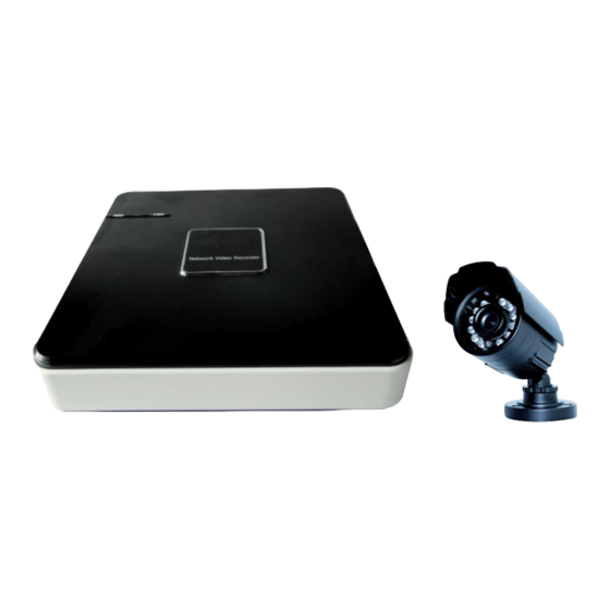
- Page 1 D5004FH+C1030DP7*4 D5008DH+C1030DP7*4 Instruction Manual...
-
Page 2: Precautions
1. PRECAUTIONS Please observe the following precautions to avoid damage or data loss caused by improper operation. The DVR will work properly when used within the specified temperature and humidity levels. Do not install the DVR in a dusty, humid, or smoky environment. This device requires a stable, flat surface for proper operation. -
Page 3: Table Of Contents
CONTENT PRECAUTIONS ..........................1 NOTEs ............................1 PRODUCT INTRODUCTION ....................... 4 3.1. Introduction ........................4 3.2. Features .......................... 4 3.3. Installation ........................5 3.4. Panel Introduction ......................7 3.5. USB Mouse ........................8 3.6. Input Method ........................8 3.7. Power On/Off ......................…. 9 3.8. - Page 4 5.4. Voice Intercom .......................66 5.5. Hard Disk redundancy ....................67 5.6. HDD S.M.A.R.T......................68 5.7. Updating Firmware:......................69 5.8. Glossary .........................71 5.9. Hard Drive Capacity .......................72 5.10. Common Faults......................75 Appendix1. Camera User Manual ......................78...
-
Page 5: Product Introduction
3. PRODUCT INTRODUCTION 3.1. INTRODUCTION Congratulations on your purchase of the WinBook Security 8 Channel DVR Security System. The included Digital Video Recorder (DVR) and Night Vision Cameras are an ideal solution for securing your personal and commercial lifestyles. This DVR supports synchronized video playback and monitoring, select network-based system controls, and several network streaming capabilities. -
Page 6: Installation
3.3.1. CHECK DVR AND ACCESSORIES Your surveillance system should include the following items. If anything is missing please accept our apologies & immediately notify your nearest WinBook Security distributor. • Digital Video Recorder (8 channel DVR) • 4 x Night Vision Security Cameras •... - Page 7 WARNING: Do not power any electrical devices involved in installation until all video and camera connections have been made. Step 1: Connecting Your WinBook Security DVR to a TV or Monitor Before connecting your DVR, please ensure the proper video ports are available on your TV or monitor.
-
Page 8: Panel Introduction
Step 4: Powering your devices Cameras – Connect the red female power connection of each 60’ extension cable into the provided power splitter. Connect the female power splitter end into the male end of the power supply. Plug power supply into an available surge protector or wall socket. Plug the labelled DVR power plug into the DVR 3.4. -
Page 9: Usb Mouse
Rear Panel Instruction for D5008DH DIAGRAM 3-4(G) Index Name Description Video input Composite video signal (CVBS) input interface. Video output Composite video signal (CVBS) output interface. HD OUTPUT HD output interface. VGA output interface. Audio input/output Audio input/output interface. USB/Network USB2.0 and RJ-45 interface. -
Page 10: Power On/Off
D IAGR AM 3 -5 L ETTER IN PU T IN TER FAC E Number Input Interface D IAGR AM 3 -6 N U MBER IN PU T IN TER FAC E Special Symbols Input Interface Diagram 3-7 SPECIAL SYMBOLS INPUT INTERFACE 3.7. - Page 11 D IAGR AM 3 -8 L IVE VIEW Note: The included power supply is rated for exact use with your DVR Kit, substitution of the device is not recommended and may void your warranty. 3.7.2. POWERING OFF Select the SHUTDOWN option in the main menu of the DVR. 【Main Menu】→【Shutdown】→【Shutdown】.
-
Page 12: Menu Icons
D IAGR AM 3 -9 TU R N OFF D EVIC E NOTE: Ensure DVR is completely powered off before replacing any component, including hard drives. 3.7.3. OUTAGE RECOVERY If you have to reboot after a power outage or forced shutdown, the DVR will have saved any files before the power outage occurred and will return to the normal operation mode. -
Page 13: Live View
:Copy current settings to other channels :Enter the configuration menu :Configures alarm, video detection and trigger processing 3.9. LIVE VIEW Turn the DVR on to enter live view mode. The date, time, channel names or icons will be displayed and indicate any recording or alarm statuses on-screen. You can switch display screens by using the USB mouse. - Page 14 3.10.1. SCREEN SWITCHING A maximum of eight channels can be displayed on one monitor screen. The operator can choose to display one, four, or eight channels. 3.10.2. PAN/TILT/ZOOM CONTROL (OPTIONAL) Select Output P/T/Z to set P/T/Z protocol, baud rate or address bits. For details on doing this, refer to chapter 5.4.
- Page 15 Note: Different modes have different functions. 3.10.4. SEARCH Refer to 3.12 Search. 3.10.5. RECORDING VIDEO Note: You must follow these directions to configure the desired recording schedule for your DVR. While in the live view screen, click on the 【Record】 button. This will bring up the manual recording interface, as shown in Diagram 3-4 Recording Control.
- Page 16 3.10.6. MAIN MENU Click the 【Main Menu】, enter a User name and password, click 【OK】 to enter the system menu, as shown in Diagram 3-5 system Login below. D IAGR AM 3 -5 SYSTEM L OGIN Default Users: User Type User Name Default Password Administrator...
-
Page 17: Main Menu Introduction
3.11. MAIN MENU INTROD UCTION The Main Menu has six navigable fields: Search, Configuration, Maintenance, Output, Storage, and Shutdown. D IAGR AM 3 -6 SYSTEM MAIN MEN U 【Search】 Search recorded video by type, channel, time and playback. 【Configuration】 Configure recording, motion detection, abnormalities, alarm, system, network and user management settings. -
Page 18: Main Menu > The Search Menu
3.12. MAIN MENU > THE SEARCH MENU You can call up the 【SEARCH】 interface through the Main Menu, as shown in Diagram 3-7 Record SEARCH DIAGRAM 3-7 RECORD SEARCH... - Page 19 Index Type Description Calendar Click a specific date to call up the recording. The list is upgraded automatically. Time Select recording search start and end time. Playback control: stop/play, pause, fast, slow, previous/next frame when in Play pause mode. Recording Choose searched recording mode, including NORMAL, ALARM &...
- Page 20 Playback Control: Description Remark During playback, pressing this key, Video playback : allows you to Fast-Forward with a number of speeds to choose from. The Fast-Forward Fast-Forward button can also be used button as a reverse of the Slow Motion key. During playback, pressing this key Actual play rate is based on provides a variety of slower playback...
-
Page 21: Main Menu > The Configuration Menu
3.13. MAIN MENU > THE CONFIGURATION MENU You can access the Configuration menu through the Main Menu. This menu gives you access to several additional menus including: System, Record, Network, Alarm, Account, and Abnormity. As shown in Diagram 3-8 Configuration below. D IAGR AM 3 -8 C ON FIGU R ATION 3.13.1. - Page 22 【System Time】:Sets the current date and time Note: Click [Save] to save any time change. 【Date Format】: Modifies the displayed date format. 【DST】: Click the DST (Daylight Saving Time) box to enable this function, and enter your local DST starting and ending dates. 【Date Separator】: Selects the separator for the date (User preference).
- Page 23 3.13.2. CONFIGURATION MENU > THE RECORD MENU The second item in the Configuration menu is Record. Click on it to call up the menu. There are two tabs in the Record menu, Local Channel and Record Plan. RECORD MENU - The Local Channel Tab The “Local Channel”...
- Page 24 【Bit Rate Control】: Options are CBR (Constant Bit Rate) or variable Bit rates. Bit rates can be set to Constant Bit Rate or there are 6 levels of image quality in the Variable Bit rate options of which 6 is the best. The default is CBR. 【Audio】: Enable or disable concurrent audio recording for the selected video channel.
- Page 25 Note: One or both of these boxes must be checked for the next two display items to function. 【Channel Display】: Click on the Set button. The video feed for the selected channel will appear in full-screen mode displaying the channel title. This saves instantly. You can quit by clicking the right mouse button.
- Page 26 D IAGR AM 3 -1 2 R EC OR D IN G C ON FIGU R ATION SC H ED U L E 【Channel】:Selects the video feed channel. To select a channel, click on the arrow at the right of the selection box and a channel list will drop down. Select the required channel. Green, Yellow, and Red represent: Regular (Green), MD (motion detection –...
- Page 27 D IAGR AM 3 -1 3 ED IT PL AN 【Record Type】: Sets a desired time period for recording. There are up to six configurable time periods which can be selected for recording during each 24-hour period. 【Regular】: For normal recording. 【MD】: For recording during motion detection.
- Page 28 D IAGR AM 3 -1 4 N ETWOR K C ON FIGU R ATION -BASE C ON FIGU R ATION Network Card Type: The network card type is fixed for this device. The DVR has a built-in Wired Network (LAN) card. 【DHCP】: Allows the DVR to obtain an IP address automatically.
- Page 29 The Advanced settings tab allows you to configure the listed network functions. The Setting button beside each item accesses a pop-up window with settings for that item. Advance settings tab interface (Diagram 3-15 Network Configuration - Advanced): D IAGR AM 3 -1 5 N ETWOR K C ON FIGU R ATION - AD VAN C ED 【PPPOE】: Enables the PPPOE feature.
- Page 30 【NTP】: Turns NTP on/off. Network Time Protocol – allows the DVR to automatically sync with an SNTP time server. Server IP: Enter the IP address of the NTP server. Port: If the SNTP server only supports TCP, the unique port is 123. Update Cycle: The interval options are between 1 min and 65535 min.
- Page 31 【Email】: Set the sender mailbox SMTP server IP address, port, username, password and sender’s mailbox, mail SSL Encryption. Email title supports Chinese, English and Arabic numerals, Input maximum: 32 characters. Max supports: 3 Receiving Addresses and SSL Encryption Mailbox. 【FTP】:click “Set” Set FTP server IP address, port and destination folder.
- Page 32 CONFIGURATION menu > the ALARM menu The Alarm menu contains settings for the DVR's alarm functions. The menu has three tabs: Detect, Net Alarm, and Local Alarm. Note: D6104FV/D6108DV (4-channel and 8-channel DVRs) have no LOCAL ALARM Function so this tab is not functional. Detect Tab Settings Detect tab interface Diagram 3-16 Alarm Configurations: D IAGR AM 3 -1 6 AL AR M C ON FIGU R ATION S...
- Page 33 【Process】: To enter the alarm configuration interface. D IAGR AM 3 -1 7 AL AR M C ON FIGU R ATION -D ETEC T-PR OC ESS MOD E -PER IOD 【Period】: Sets the alarm activity period. Click “set” and then select up to 6 different period times that the alarm is to be activated (check the box and then select the times from and to the alarm should be activated –...
- Page 34 【Linkage Set】: to activate which monitoring method will be used: 【Record Channel】: continuous recording with all channels with time delay that is set. 【PTZ】: recording using an attached PTZ camera (recording modes are: none, preset, tour and pattern. 【Tour】: continuous recoding using the “tour” method (recoding from one camera to another).
- Page 35 3.13.4. CONFIGURATION MENU > THE ACCOUNT MENU The Account menu contains settings for managing system Users and groups of Users. Note: Group and User names can be from 1-6 characters in length. Valid characters include letters, numbers, and limited symbols (underlining, dash and dot). You may not use a space as a beginning or ending character.
- Page 36 Click 【Add User】 to call up the sub-menu then enter a User name, password and select the group and reusable options. Clicking reusable allows the account to be used for multiple logins. *NOTE* Users can only belong to one Group and User rights cannot exceed Group rights. 【Modify User】: Modifies existing group member information and authorizations.
- Page 37 3.13.5. CONFIGURATION MENU > THE ABNORMALITY MENU The Abnormality menu enables and configures system warnings and error messages. Diagram ABNORMALITY: 3-21 DIAGRAM 3-21 ABNORMALITY...
-
Page 38: Main Menu > The Storage Menu
There are five items in the Abnormality menu. To activate a warning or error message function, click on the check box beside it. The Process button beside each item gives access to further settings for that item. 【No Disk】: Displays a warning when the internal hard disk drive is not present or can’t be detected. - Page 39 Diagram 3-22 STORAGE MANAGEMENT DIAGRAM 3-22 STORAGE MANAGEMENT Base Configuration 【HDD Base】 as shown in Diagram 3-23 HDD management –base configuration, shows DVR storage capacity, available space and operational status. *NOTE* the acronym HDD refers to “Hard Disk Drive”...
- Page 40 D IAGR AM 3 -2 3 H D D MAN AGEMEN T – BASE C ON FIGU R ATION 【Format】: Enables User to format the DVR’s internal hard disk. Note: Formatting a hard disk erases all data on the drive. 【Set】: This controls the hard disk’s access mode setting.
- Page 41 The HDD Record Tab HDD Record menu, as shown in Diagram 3-25 HDD Management-record, displays a recording log with recording start and stop times. D IAGR AM 3 -2 5 H D D MAN AGEMEN T-R EC OR D 3.14.2. STORAGE MENU > THE BACKUP MENU Connect an External USB device to one of the USB ports to back up recordings from the DVR’s internal hard disk using the commands in the “Backup”...
- Page 42 【Detect】: Identifies the external USB device and displays the device information. 【Backup】: Click on the box for the target external drive then click on 【Backup】 to enter the Backup menu (see Diagram 3-27 Backup). D IAGR AM 3 -2 7 BAC KU P Select the recording’s Start and End times and click 【Add】...
-
Page 43: Main Menu > The Output Menu
DVR system.Diagram 3-28 Peripheral Management shows the Output menu interface. Note: The WinBook Security model included with your kit does not offer P/T/Z nor RS232 functionality. D IAGR AM 3 -2 8 PER IPH ER AL MAN AGEMEN T... - Page 44 3.15.1. OUTPUT MENU > THE DISPLAY MENU Display menu sets the unit's display and polling features. The menu has three tabs, GUI, Output Configuration and Tour Configuration. Display M enu D IAGR AM 3 -2 9 OU TPU T-D ISPL AY MEN U The GUI tab sets the appearance of the On Screen Display (OSD).
- Page 45 The Output Configuration Tab The Output Configuration tab displays several control settings for a video display monitor connected to the DVR system via the VGA port. D IAGR AM 3 -3 0 OU TPU T C ON FIGU R ATION 【VGA Output Resolution】: Select VGA resolution and refresh rate, the default setting is 1024 ×...
- Page 46 The Tour Configuration Tab The Tour Configuration tab sets up and enables the touring functions. D IAGR AM 3 -3 1 TOU R C ON FIGU R ATION (OPER ATION IS TH E SAME FOR BOTH TH E 4 - & 8 -C H AN N EL D VR S) This menu sets up the tour mode and intervals between rotations.
-
Page 47: Main Menu > The Maintenance Menu
3.16. MAIN MENU > THE MAINTENANCE MENU The following graphic shows the Maintenance menu interface (Diagram 3-32 Maintenance). D IAGR AM 3 -3 3 1 MAIN TEN AN C E 3.16.1. MAINTENANCE MENU > THE LOG MENU 【LOG】: Displays system log information. D IAGR AM 3 -3 4 L OG... - Page 48 To view log entries, select the log type and desired time segment and then press the Find button. The system will display the log in tab form. You can also click the backup button to export the logs to your computer for backup. Log types: system operation;...
-
Page 49: Main Menu > The Shutdown Menu
Note: Menu transparency, language, time format, video format, IP address, user IDs, etc. are not affected. 3.16.4. MAINTENANCE MENU > THE BPS MENU 【BPS】: Displays the video size and data rate of each channel by waveform. Note: These are estimated values and are for reference only. 3.16.5. -
Page 50: Web & Client
4. W EB & CLIENT 4.1. WEB OPERATION 4.1.1. NETWORK CONNECTION You can check the LED indicator on the back of your DVR to verify Ethernet connectivity. When the LED is lit, it indicates a working network connection. Configure your IP address, subnet mask and gateway for the computer and DVR. If you are not using DHCP, you will need to ensure the following settings are in place under the Network Configuration Base Menu: ... - Page 51 NOTE: Some users may experience a continued error when trying to access the web interface over Internet Explorer, most often in relation to Active X security settings. The following steps should be taken to solve this error: 1. Under the “Internet Options” menu in, navigate to the “Security” Tab: 2.
- Page 52 a. Enable the “Allow previously unused ActiveX controls to run without prompt” function. b. Enable the “Allow Scriptlets” function. Enable the “Display video & animation on a webpage that does not external media player” function. d. Enable the “Prompt” feature for the “Download unsigned ActiveX controls” function. e.
- Page 53 Click “Install”, the re-open the browser, the following tips will be shown as below. Click the “ Yes” button to install the Active-X plug-in automatically. After installing the Active-X plug-in, you can input your User name (default: admin), password (default:123456) and click “Login”. After the user login process succeeds, click “Exit” to quit. Please refer to “Diagram 4-3 WEB Interface”...
- Page 54 4.1.2. WEB OPERATION INTERFACE D IAGR AM 4 -3 WEB IN TER FAC E Index Function Description Channel Channel selection Local playback: playback local recording Function key Open all: play live views in surveillance window Surveillance window Change window layout Image color: modify brightness, contrast, saturation and hue Image color &...
- Page 55 In the Web interface, select the focus window in the live window. The focus window has a light blue border. From the left channel column, select the channel, as shown in Diagram 4-2 Channel Choices: D IAGR AM 4 -2 C H AN N EL C H OIC ES Click on area in upper right corner, this allows you to choose to open or close the channel to the main stream or secondary stream.
- Page 56 Capture: Captures the present video channel. Set up the path in “Other”. Sound: Turns audio on or off. Video Off: Turns off the focus window. D IAGR AM 4 -4 FU N C TION IC ON S 4.1.4. CONFIGURATION Access the DVR’s local configuration menu by clicking on “Configuration”. For further details please refer to 【Local operation guide】...
- Page 57 D IAGR AM 4 -5 C ON FIGU R ATION 4.1.5. SEARCH RECORD Click “Search” to open the search window (Diagram 4-10 ). You can search and operate recordings, alarms, motion detection, and local recordings. Search Record...
- Page 58 D IAGR AM 4 -1 0 SEAR C H R EC OR D By selecting the recording type, starting and ending times, and clicking the search button, you can obtain a list of files on the DVR. Select the desired file and it can be played. Play Double-click a search result to play it in the video window.
- Page 59 4.1.6. ALARM CONFIGURATION Click 【Alarm】 to enter the alarm setup menu. You can set up and operate the alarm functions, as shown in Diagram 4-6 Alarm . Choose the type of alarm in the menu; monitor video loss, motion detection, disk full, disk error, video mask, and external alarms.
-
Page 60: Functions
5. FUNCTIONS 5.1. DDNS FUNCTION 5.1.1. SUMMARY Dynamic DNS is a kind of system which assigns an internet domain name to a variable IP address. According to the rules of internet domain names, a domain name must associate with a fixed IP address. - Page 61 Domain name xxx.3322.org Username Password xxxxxx After setting up the information as shown above, you can access the Embedded DVR via XXX.3322.org Notice: The main machine’s IP address should refer to the information on the website. 5.1.4. NO-IP(WWW.NO-IP.COM) Register Register a new user name at No-IP and click on 【Create Account】. Create a domain name and click on 【Add a Host】.
- Page 62 Click on the confirmation link, to log in to the account, click 【Add Host Services】 in [My Services], set your own real name and then follow the directions. Configuring the DVR Open 【Main Menu】→【Configuration】→【Network】→【Advanced】→【DDNS】→【 Enable】 Item Configuration DDNS Dyndns DDNS Members.dyndns.org Port Domain name...
- Page 63 Port Domain name xxx.dvrlist.com Username Password xxxxxx 5.1.7. TEST AND VERIFY DDNS After configuring the Embedded DVR, wait for a few minutes to allow the analysis records to update. Click on Operation in the menu, input “cmd” and click “OK” to open a command line window, as shown in Diagram 5-1 Run Command Line Program.
- Page 64 D IAGR AM 5 -2 D N S The computer will analyze the domain name configured in the DVR, and return to the current IP address, as the graphic shows underlined in red. When the IP address corresponds to the embedded DVR’s IP address in Public internet, it means the DDNS is set up correctly.
-
Page 65: Port Forwarding
5.2.1. UPNP FUNCTION In order to get a connection to the DVR through a Public network, we need to set the Router to cross the NAT of the DVR. UPnP can make the NAT cross automatically via the UPnP agreement of the DVR, and you don’t have to set up the Router. -
Page 66: Ntp Function
The second step Log in to the Router, access its configuration menu, and enter the required settings. Then go to the port, set the IP address distributed by the DVR, and set the rules for port mapping, add the HTTP and TCP ports to the mapping list. -
Page 67: Voice Intercom
NTP Server Set Up under Windows “Start” menu → “Run”, input “regedit” to enter the registry editing feature. Build a new key assignment of DWORD Value by going to: HKEY_LOCAL_MACHINE\SYSTEM\CurrentControlSet\Services\W32Time\Parameters\registry sub key (NtpServer); Change the value to 1, and save. Restart the computer. -
Page 68: Hard Disk Redundancy
Note: The audio needs to be connected to a powered audio output device. Remote PC Configuration Connect a microphone and powered speakers to the computer. Enable bidirectional communication in the client software or the Web interface. 5.5. HARD DISK REDUNDANCY The hard disk drive (HDD) redundancy function can backup recorded files. -
Page 69: Hdd S.m.a.r.t
5.6. HDD S.M.A.R.T S.M.A.R.T, or “Self-Monitoring, Analysis and Reporting Technology”, is a hard disk technology that is incorporated into some hard disk drives. A S.M.A.R.T HDD can analyze the drive’s head, disc, motor, circuit operation, history and default security values via monitoring instructions in the HDD and the surveillance software. An alarm will automatically be sent to the user when a value is outside the scope of the security situation. -
Page 70: Updating Firmware
200 Write Error Count Note: Different manufacturers and different models have different attribute descriptions. The user does not need to know the exact meanings, and attribute detection values are good enough. 3 Threshold This is specified by a manufacturer-calculated formula. If there is an attribute value lower than the threshold, this means the HDD has become unreliable and could easily lose data stored on it. - Page 71 (3) Enter the IP address and TCP port code of the DVR device. Click on Login and a login window will display: (4) Enter a User name and password and click on OK to log in to the DVR: (5) Drag the "updatepacket.bin" file to the entry box which shows after opening the files as illustrated below:...
-
Page 72: Glossary
(6). Click the BIOS button to the updating. (7). USB UPDATE Re-name the updatepacket.bin file to vss.bin, put it into the root directory of a USB drive, then plug the USB drive into the USB port on the DVR. Using the DVR’s OSD interface, go to Main Menu > Maintenance >... -
Page 73: Hard Drive Capacity
B Frame B frame: According to a time redundancy of the source image sequence, the previously encoded frame accounts for the source image after the encoded frame is compressed, also known as the bi- directional prediction frame. P Frame P-frame: Image frames are lower quality than the previous B Frame, also known as predicted frames. - Page 74 HDD Recording Capacity = number of channels × time in use (hours) × HDD space used per recording hour (MB/hour) You can calculate the formula for recording time: ( ) TotalHDDCa pacity ( ) ecording time hour ( )...
- Page 75 D IAGR AM 5 -1 3 SEAGATE D OWN L OAD b) Double-click to install the downloaded file, then click on the installed file to detect HDD information for the PC. c) Choose the HDD for detection (other manufacturer’s hard disk are suitable too) . How To Detect Western Digital HDDs a) Go to www.wdc.com , choose WD support / download / SATA&SAS / WD Caviar / GP then download the software as shown in Diagram 5-14 WD Download.
-
Page 76: Common Faults
D IAGR AM 5 -1 5 WD D ETEC T 5.10. COMMON FAULTS DVR startup failure or continuous reboot Possible reasons: The system has been damaged by a bad DVR update. There is a problem with the DVR main board, please contact your supplier. There is an HDD error. - Page 77 HDD error, test or replace the HDD. DVR hardware failure, contact your supplier. Cannot connect to DVR through network Possible reasons: 1. Check if the network connection is correct. 2. Check if the DVR network configuration parameters are correct. 3. Check whether IP address conflicts exist in the network. Downloaded recording cannot be played Possible reasons: 1.
- Page 78 Close Internet Explorer, restart it, access Internet Options from the Tools menu and go to the Advanced tab. Make sure the memory protection item is not enabled. See the following: D IAGR AM 5 -1 4 IE TOOL BAR Internet Explorer 9.0 or above Please use a compatible mode if you are having operation function difficulty with your IE browser.
-
Page 79: Appendix1. Camera User Manual
APPENDIX1. CAMERA USER MANUAL C1030DP7 1. INTRODUCTION This infrared CCTV camera is designed with Infrared LEDs, enabling Night Vision. 2. CAUTIONS (1) Do not place the camera in direct sunlight, rain, or dust. (2) Do not touch the CMOS sensor with your fingers. If cleaning is necessary, please use a soft cloth moistened with a little alcohol to wipe off any dust. - Page 80 Camera Monitor CAMER Power supply adapter 4. TECHNICAL SPECIFICATIONS Image Sensor: 1/4″ CMOS Effective Pixels: NTSC: 720(H) x 480 (V) Signal System: NTSC Horizontal Resolution: 700TV Lines Lens: 3.6mm Minimum Illumination: 0 Lux Back Light Compensation: Internal Shutter Speed: 1/60 ~ 1/100,000 sec White Balance: Auto S/N Ratio: More than 48db (AGC OFF) Video Output: 1.0Vp-p, 75Ω...
- Page 81 FCC Statement: This device complies with part 15 of the FCC Rules. Operation is subject to the following two conditions: (1) This device may not cause harmful interference, and (2) this device must accept any interference, including interference that may cause undesired results. Warranty Statement: This product is covered by standard warranty terms and conditions for a period of 12 months from the date of purchase.
Need help?
Do you have a question about the D5004FH+C1030DP7*4 and is the answer not in the manual?
Questions and answers