Table of Contents
Advertisement
Advertisement
Table of Contents

Summary of Contents for Logitek ULTRA-VU
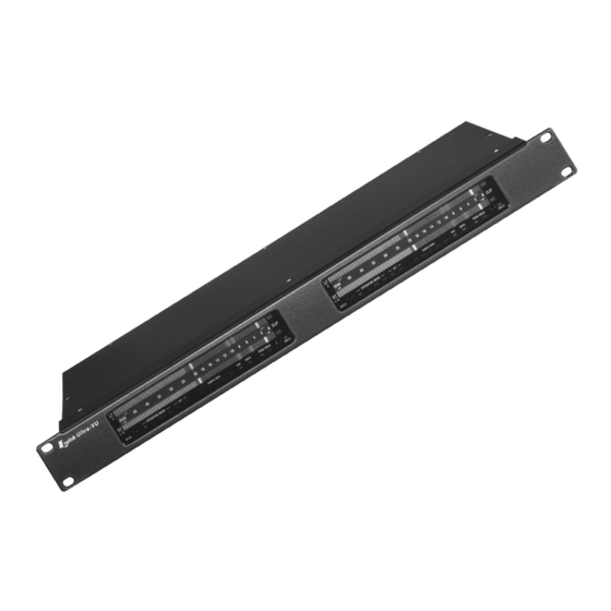
- Page 1 Logitek ULTRA-VU LED BARGRAPH AUDIO METER Operation & Service Manual...
- Page 2 Logitek grants to you the right to use one copy of the embedded soft- ware in each Ultra-VU meter you purchase. You may not rent or lease the software. You may not reverse engineer, decompile, disassemble, or cre- ate derivative works from the software. You may not create copies of the software.
-
Page 3: Table Of Contents
Ultra-VU LED Meter OPERATION & SERVICE MANUAL TABLE OF CONTENTS SECTION 1— GENERAL INFORMATION General Description ..........3 Electrical Specifications . -
Page 4: Section 1- General Information
SECTION 1— GENERAL INFORMATION 1-1 General Description Dimensions: The Logitek Ultra-VU is a bargraph type audio me- 1RU enclosure 19" W x 7" D x 1 ’ ter featuring two tricolor LED bargraphs with clip indi- Desk top enclosure “ W x 9" D x 2 ”... -
Page 5: Section 2 - Preparation For Use
2-2 Claims signal. This happens even if nothing is connected to the analog inputs. The Ultra-VU can be forced to dis- If the unit has been damaged, notify the carrier im- play only one input by connecting a remote switch to mediately. -
Page 6: Connecting Analog Input Models
1. Switch 2 sets the dynamics of the peak display. True peak shows the The Ultra-VU shield pins are bonded directly to the largest single peak. This mode is useful for avoiding chassis at the connector and do not share any ground digital clipping. -
Page 7: Section 3 - Operating Instructions
If the holding period expires before the PPM dot equals or exceeds the peak hold The Ultra-VU display contains two multi-LED bar- dot, then the peak hold dot will turn off. It will turn on graph displays mounted one above the other. The top again when the PPM dot reaches a peak and starts bar shows either left channel (L) or image/phase(φ) -
Page 8: Fine - High Resolution Mode
3-11 Resetting the Program 3-7 FINE — High Resolution Mode The Ultra-VU contains software that executes on a Fine is a high resolution mode that expands the programmable DSP chip. If the processor memory meter scale to .2 dB per segment around the 0 VU... -
Page 9: Section 4 - Maintenance
SECTION 4 — MAINTENANCE 4-1 General Information 4-4 Access to Circuit Cards The Ultra-VU is designed to need a minimum of Access to the circuitry of the rackmount and half- maintenance for long trouble-free operation. Should rack meters is accomplished by removing the six repair be necessary, the technician should first read screws that attach the top cover. -
Page 10: Digital/Dual Input Control Card Lg-265
P2. Note that no buffering is applied to the loop change, such as when it is first powered up, it may through output. generate noise up to -70 dBFS until it undergoes a calibration cycle ** Ultra-VU Operation & Service Manual ** Page 10... -
Page 11: Display Assembly Lg-267
+5 VDC from the DSP control card. nel). IC3 and IC4 drive the lower bargraph (right channel). IC5 drives the scale indicator LEDs along the bottom edge of the display. Page 11 ** Ultra-VU Operation & Service Manual **... -
Page 12: Section 5 - Replacement Parts List
SECTION 5 — REPLACEMENT PARTS LIST All replacement parts are stocked in depth at the Logitek factory. Most are also available through local electronic parts distributors. For your convenience in purchasing replacement parts locally, we include the following parts list. -
Page 13: Digital/Dual Input Control Card
CT-MP122 1 pc. Circuit Card LG-266 (Analog Control) Digital/Dual Input Control Card Capacitors .047uf/1000V ceramic CE-CW-20C473K C2-4 10uf/25V tantalum AV-TAP106K025HSB C5-10 .1 uf/50V SMD NC-NMC1206Z5U104M50T 25pf/1000V ceramic CE-DD-250 15pf/1000V ceramic CE-DD-150 Page 13 ** Ultra-VU Operation & Service Manual **... -
Page 14: Display Assembly
D64-125 Tricolor LED bar 2mm x 5mm SY-VBRG5641X (order by brightness number on display card) D126 Red LED bar 3mm x 6mm QT-MV57124A D127-141 Yellow LED bar 3mm x 6mm QT-MV53124A ** Ultra-VU Operation & Service Manual ** Page 14... -
Page 15: Adc Input Card
FR1-3 Ferrite bead MU-BLM32A07PB Resistors R1,2 21k, .1% DL-RNC55H2102BS R3-7 4220, 1% R8,9 50K multiturn trimpot MP-CT9X503 R10,11 21K, .1% DL-RNC55H2102BS 4220, 1% R13-14 1 pc. ADC Input circuit card LG-264A Page 15 ** Ultra-VU Operation & Service Manual **... -
Page 16: Section 6 - Manufacturers List
Sunnyvale, CA Signetics Corporation Sunnyvale, CA Signal Transformer Inwood, NY Schurter Inc. Petaluma, CA Schott Corp. Minneapolis, MN Switchcraft, Inc. Chicago, IL Stanley Battle Creek, MI Texas Instruments, Inc. Dallas, TX ** Ultra-VU Operation & Service Manual ** Page 16... -
Page 17: Section 7 - Diagrams
SECTION 7 — Diagrams Page 17 ** Ultra-VU Operation & Service Manual **... - Page 18 ** Ultra-VU Operation & Service Manual ** Page 18...
- Page 19 Page 19 ** Ultra-VU Operation & Service Manual **...
-
Page 20: Analog Input Control Card
** Ultra-VU Operation & Service Manual ** Page 20... - Page 21 Page 21 ** Ultra-VU Operation & Service Manual **...
-
Page 22: Dual Input Control Card
** Ultra-VU Operation & Service Manual ** Page 22... - Page 23 Page 23 ** Ultra-VU Operation & Service Manual **...
-
Page 24: Display Assembly
** Ultra-VU Operation & Service Manual ** Page 24... - Page 25 Page 25 ** Ultra-VU Operation & Service Manual **...
- Page 26 ** Ultra-VU Operation & Service Manual ** Page 26...
- Page 27 Page 27 ** Ultra-VU Operation & Service Manual **...
-
Page 28: Adc Input Card
** Ultra-VU Operation & Service Manual ** Page 28... - Page 29 Specifications warranty extends to the original purchaser only. are subject to change without notice. EXCEPT AS LOGITEK will repair or replace, at its option, at its SPECIFICALLY PROVIDED HEREIN, LOGITEK factory without charge professional equipment if a...
Need help?
Do you have a question about the ULTRA-VU and is the answer not in the manual?
Questions and answers