Advertisement
Quick Links
Advertisement

Summary of Contents for OMP 70” FUSION
-
Page 1: Instruction Manual
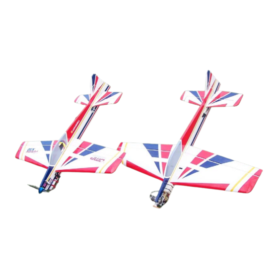
70” FUSION Instruction Manual Wingspan: 70" Wing Area: 1045 sq. in. Length: 69.5" Approx. Weight: 7.25-7.75 lbs. Engine: 1.20 glow, 20 cc gas E50-E60 motor with 1900-2100 Watts OHIO MODEL PRODUCTS, 199 Stratford Lane, Xenia, Ohio 45385, (937) 372-0603 www.ohiomodelplanes.com... - Page 2 This does not cover any parts damaged by use, misuse, modification, or long term storage. In no case shall OMP's liability exceed the original cost of this kit. Because OMP has no control over the final assembly or equipment/components used in the final assembly, no liability shall be assumed for any damage resulting from the use of this model by the user.
- Page 3 Radio Gear COVERING: 1. OMP recommends lightly going over all the covering with a covering iron set at medium temperatures. With all ARFs, varying temperatures and transport delays can cause covering material to loosen over time. Pay attention to all covering seams and make sure all are properly adhered to the model.
-
Page 4: Radio Selection
OMP profiles utilize a very tight double beveled hinge line and do not normally require this step. Sealing the hinge gaps is therefore left as an option for the modeler. If desired this can be accomplished using strips of clear covering applied along the hinge lines after the surfaces have been installed. -
Page 5: Airframe Assembly
AIRFRAME ASSEMBLY: 1. Flat nylon hinges are provided for this model and the slots have been pre-cut by the factory. Hint: clean the hinges first with isopropyl alcohol to remove any plastic mold release agent prior to gluing in place. Also, lightly sand them to take the shine off. - Page 6 wheel to spin freely), inserting into the gear and then securing with a nylon insert lock nut on the inside of the gear. 4. Locate the tail wheel parts as shown below. Install the tail wheel onto the spring wire and secure in place using the supplied wheel collars.
- Page 7 6. Temporarily install the wings onto the fuselage making sure they are fully seated onto the fuselage. Tighten the center wing bolt to make sure the wings are tight and square to the fuselage. The center bolt is inserted through the left wing hatch and passes through the root rib, fuselage, and into the blind nut in the right wing. 7.
- Page 8 surface and are centered on the hinge line. Clean off any excess glue and tape the elevators in place while the glue dries. 10. Now locate the carbon fiber horns (4) two for each side. Locate the two slots in the elevators and carefully remove the covering to expose the slot on the bottom only.
- Page 9 ENGINE, TANK, AND RADIO GEAR GAS/GLOW VERSION: Note: If you have the electric version, scroll down to the Electric section for directions on how to install motor, ESC and batteries. 1. Locate the fuel tank and assemble the stopper, fuel lines, and tank clunk according the photo below. Carefully bend the vent line upward toward the top of the tank.
- Page 10 4. Install the tail servos into their respective sockets and pull the wires through the tunnel by taping the ends to a piece of long nylon pushrod or similar semi-flexible wire. The two elevator servos are stacked one on each side of the fuselage.
- Page 11 accurate measurement. Once you have determined the engine placement, drill the holes and mount your engine using the supplied bolts, washers, and locking nuts. Use thin CA on the inside of the holes to harden them up. You may wish to add about 2-3 degrees of right thrust by adding washers or wedge plates under the engine before mounting.
- Page 12 counter sunk through the mount and into the hardwood behind the mount or drill and use dowels to help secure the mount to the plane. When you mount the motor, you can use washers to give a 2-3 degrees of right off set if desired.
-
Page 13: Radio Setup
8. OMP has done a lot testing to the electric set up on the Fusion and recommends the Hacker A50-14L with a 100 AMP ESC and an APC 18X8 prop. We also recommend using two 4 cell 4000 mah capacity lipo batteries connected in series with a Y-harness to produce an 8-cell lipo power. - Page 14 To perform properly without being too squirrelly, you must not go too aft on the CG. OMP recommends an initial CG setting of 8.3 - 8.9 inches behind the leading edge of the wing at the root. More experienced pilots may want to set the CG further aft. Varying weights of engines and radio gear will dictate how you should install each.


Need help?
Do you have a question about the 70” FUSION and is the answer not in the manual?
Questions and answers