Table of Contents
Advertisement
Advertisement
Table of Contents

Subscribe to Our Youtube Channel
Summary of Contents for Alpha Telecom UT3620 Triple NT1
- Page 1 UT3620 Triple NT1 Installation Guide...
-
Page 3: Installation Guide
UT3620 Triple NT1 Installation Guide Revision 1.03 8/14/2008 Information in this guide is subject to change without notification. - Page 4 Copyright 2000-2008 Alpha Telecom, Inc. U.S.A. This document may only be distributed, in printed or electronic form, by Alpha Telecom, or by parties authorized by Alpha Telecom.
-
Page 5: Table Of Contents
Table of Contents Important Safety Instructions Introduction Package Contents Front Panel Rear Panel Wiring Instructions Appendix A: DIP Switch Positions Appendix B: S/T Bus Configuration Appendix C: Interface Pin Assignments Appendix D: Power Source 2 (PS2) Appendix E: Acronyms FCC Notice ETL/ETLC Notice Industry Canada Information Metallic Loop Test (MLT) -
Page 6: Important Safety Instructions
Important Safety Instructions If you experience technical difficulty with the UT3620 please contact Alpha Telecom at 408-895-1806 or support@alpha-tele.com for technical support. Never install telephone wiring during a lightning storm. Never install telephone jacks in wet locations unless the jack is specifically designed for wet locations. -
Page 7: Introduction
Equipment and ISDN Telephones. Package Contents One UT3620 Triple Three RJ-45 to RJ-45 cables Three RJ-11 to RJ-45 hybrid cables Six wire ties for cable management One power supply (16Watt or 40Watt) Manual Warranty Card Wall-Mounting Kit UT3620 Triple NT1 Installation Guide... -
Page 8: Front Panel
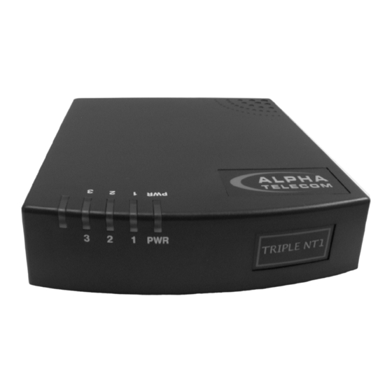
Front Panel Figure 1 shows the UT3620 in perspective view to show all of the LEDs and labels. There is a position for an extra LED at the far left which is not used in this model. There are four LEDs in the front panel of the UT3620. -
Page 9: Wiring Instructions
Bus Configuration, Page 8, for details. The manufacturer’s default DIP Switch configuration will work for a majority of installations. Adjustments should only be made if the configuration is an exception as mentioned in the Appendix B. UT3620 Triple NT1 Installation Guide... -
Page 10: Figure 4: Power Connector
Step 2: Connect the DC power plug of the power supply to the power connector on the rear of the UT3620 as shown in Figure 4. Place the power cable into the wire clip to secure it. Figure 4. Power Connector Plug the power supply into an AC power outlet. - Page 11 This is illustrated in Figure 6 on the next page. The Line Status LED will illuminate solid green indicating that the TE has synchronized with the ISDN line. Repeat this step for the remaining S/T-Interfaces. UT3620 Triple NT1 Installation Guide...
-
Page 12: Figure 6: S/T-Interface Connector
If the LED continues to blink slowly, the TE has not synchronized. Note: Video Conferencing products often require the software to be operating to achieve synchronization. Check the RJ-45 to RJ-45 cable connections, and verify both RJ-45 ports for the S/T-Interface. Also, verify the S/T Bus Configuration is correct for the installation. -
Page 13: Appendix A: Dip Switch Positions
Details of each DIP Switch are given in Table 1. The asterisks represent the default positions. Setting Off* Off* Adaptive Off* Fixed Table 1. DIP Switch Position Assignments Figure 7. DIP Switches UT3620 Triple NT1 Installation Guide... -
Page 14: Appendix B: S/T Bus Configuration
Appendix B: S/T Bus Configuration Combinations of these settings and the wiring requirements of the installation determine the configuration for each line. Each S/T-Interface is configured separately to provide flexibility. Default Configuration: The manufacturer’s default DIP Switch configuration will work on almost all installations. No more than four terminals can be attached and each terminal must be the same distance away from the NT1, within 10 meters tolerance, to a... -
Page 15: Figure 9: Short Bus Configuration
TR (or have a TR wired into the line just before the terminal). Up to eight terminals can be supported in this configuration. From NT1 to last TE is 200m TE with TR Figure 9. Short Bus Configuration UT3620 Triple NT1 Installation Guide... -
Page 16: Figure 10: Extended Bus Configuration
Extended Bus Configuration: This covers cases where more than 200 meters is required between the NT1 and the TE. Solution: Wire a TR a fixed distance from the NT1, or if only one terminal is needed, turn on a built-in TR. If a TR is wired into the line, up to four terminals can be supported as long as each is within 25 meters from the TR. -
Page 17: Figure 11: Y-Bus Configuration
25 meters of a TR. No TE symmetry is required, so one TR can have four terminals connected while the second only has one. From NT1 to TR is 140m Figure 11. Y-Bus Configuration UT3620 Triple NT1 Installation Guide... -
Page 18: Appendix C: Interface Pin Assignments
Appendix C: Interface Pin Assignments Each interface has specific pinouts which are important for electricians and technicians to know. Anyone installing wiring for the UT3620 should pay close attention to this information. All interfaces described here are located on the rear panel of the UT3620. -
Page 19: Appendix D: Power Source 2 (Ps2)
PS2 power. The specifications or documentation of the TE will have information on the watts required by the device. Unit Input Output +48VDC@250mA 16 Watt 120VAC@60Hz 40 Watt 90~264VAC@50~60Hz +42VDC@1A Table 5. Power Supply Information UT3620 Triple NT1 Installation Guide... -
Page 20: Appendix E: Acronyms
Appendix E: Acronyms A (mA) Amp (milli-Amp) Alternating Current Direct Current Dual In-line Package Hertz ISDN Integrated Services Digital Network meters Metallic Loop Test Network Termination type 1 device Power Source 2 Terminal Equipment Terminating Resistor Volts Volts AC Volts DC UT3620 Triple NT1 Installation Guide... -
Page 21: Fcc Notice
This certification means that the equipment meets certain telecommunications network protective, operational, and safety requirements. The department does not guarantee the equipment will work to the user’s satisfaction. Before installing this equipment, users should ensure that UT3620 Triple NT1 Installation Guide... -
Page 22: Metallic Loop Test (Mlt)
it is permissible to be connected to the facilities of the local telecommunications company. The equipment must also be installed using an acceptable method of connection. In some cases, the company’s inside wiring associated with a single line individual service may be extended by means of a certified connector assembly (telephone extension cord). -
Page 23: Notes
NOTES: UT3620 Triple NT1 Installation Guide... - Page 24 UT3620 Triple NT1 Installation Guide...
-
Page 25: Wall Mounting Template
Wall Mounting Template 4.73” UT3620 Triple NT1 Installation Guide...
Need help?
Do you have a question about the UT3620 Triple NT1 and is the answer not in the manual?
Questions and answers