Table of Contents
Advertisement
Quick Links
Advertisement
Table of Contents

Summary of Contents for Audio Wireless AWDR-1
- Page 1 User Manual v1.0...
-
Page 2: Table Of Contents
Push Button Controls ................... 6 Frequency Label ................... 7 Battery Compartment ................... 7 LCD Display ....................8 Using the AWDR-1 ..................11 Tuning the Receiver ................... 11 Tuning By Frequency ................11 Saving Custom Frequencies ..............11 Tuning By UHF TV Channel and Sub-Channel........12 Unit Name .................... - Page 3 TX Low Battery Indicator ................24 Headphone Monitoring Output ..............24 Powering ....................24 Connectors ....................24 Dimensions....................24 Accessories ....................24 AWDR-1 User Manual V1.0...
-
Page 4: Foreword
Safety Instructions Please read these instructions carefully before using the unit to avoid injury and damage to your AWDR-1 unit. Always include these instructions when passing the unit on to third parties ... -
Page 5: General Description
General Description The AWDR-1 Diversity Receiver offers the greatest flexibility and sound quality for crews, operators and sound recordists, whether working internationally or simply under challenging RF conditions. Its sophisticated structure comes in a lightweight yet rugged, CNC machined aluminium case, designed for extra strength and durability as well as the ability to withstand the heavy demands of location use. -
Page 6: True Diversity
True Diversity The Audio Wireless diversity receiver systems give a dramatic improvement to signal dropout problems found in dead spots when compared to other simple standard or antenna switching receivers. This is because the true diversity receiver makes use of two RF signals, and when one antenna is receiving a weak signal, the other antenna will be receiving a stronger signal, offering greater reliable coverage. -
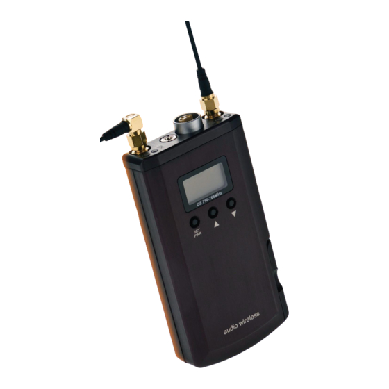
Page 7: Product Overview
AWDR-1. Headphone Monitoring Socket The AWDR-1 has a unique headphone design that auto detects Stereo or Mono Jacks when inserted into the 3.5mm socket and does not cause an electrical short or any loss of audio level. The Headphone is user adjustable to suit headphones impedances as low as 16. -
Page 8: The Led Indicators
The Low Battery Warning period depends upon the type of battery used. Antenna Input Socket A & B The miniature 50 SMA coaxial sockets are used as the antenna input connectors, the detachable matching antennas are fitted by a simple screw-on action. AWDR-1 User Manual V1.0... -
Page 9: Push Button Controls
Battery Compartment Push Button Controls All user adjustments to the AWDR-1 are made via three push buttons. Primarily use the UP and DOWN to scroll through menu’s and the SET-PWR to select choices. Alternatively at any time the SET-PWR button can be held down to turn the receiver OFF (and back ON) and by holding both the UP and DOWN buttons the receiver can be LOCKED. -
Page 10: Frequency Label
25 kHz. Alternatively the user may tune the Receiver to standard UHF TV channels with pre-coordinated sub channels. Battery Compartment The AWDR-1's AA batteries are held in place by a captive, easy-twist compartment cover, with a click-stop mechanism for quick, reliable changes possible by feel alone. -
Page 11: Lcd Display
MUTE The backlit multifunction LCD display provides clear access to all the available control menus and functions of the AWDR-1. Permanently displayed, irrespective of the currently selected menu, is the continuous AF metering of the audio signal level and RSSI level of each antennae’s RF signal and the battery level icons. - Page 12 -50 -40 -30 -20 -10 Info. Gives Unit Info -50 -40 -30 -20 -10 Pilot Option to turn off the Pilot tone system PILOT MUTE -50 -40 -30 -20 -10 On-Mode Allows for adjustment of the Power-On mode AWDR-1 User Manual V1.0...
- Page 13 All menus are set to be displayed by default. However within the display menu it is also possible to choose to show only one out of the Frequency, Channel or Name menus and hence hide the other two. AWDR-1 User Manual V1.0...
-
Page 14: Using The Awdr-1
Remember to change display mode to “All” for both menus to be available. Resetting the unit will clear all user channel pre-sets. AWDR-1 User Manual V1.0... -
Page 15: Tuning By Uhf Tv Channel And Sub-Channel
Please Note: Channel 38 (606-614 MHz), commonly used in the UK is presented with 2 sets of sub-channels. The Audio Wireless co-ordinated “A>M” set and the alternative JMFG “38-XX” option that grants a set of sub-channels numbered from 1-10. Do not mix sub-channels from both sets. -
Page 16: Unit Name
AUDIO The Audio output level of the AWDR-1 is user adjustable between +6dBV to – 42dBV to suit varying device input requirements. To do so press SET-PWR on the AUDIO menu, adjust with the UP and DOWN buttons and press SET-PWR to confirm. -
Page 17: Phase
PHASE or when hard wired boom and Radio mics may have different phase. To match the phase of other equipment used with the AWDR-1 is the ability to change the phase of the output. Simply select whether to INVERT the phase or keep it NORMAL. -
Page 18: Pilot Tone
Pilot Tone The AWDR-1 and AWT-1 series feature a Pilot Tone mechanism to only output the audio signal when it is received from the corresponding matching transmitter. Use the menu to enable or disable the feature if required. PILOT ON is recommended. -
Page 19: Locking And Unlocking The Unit
Locking and Unlocking the Unit The AWDR-1 is designed with a Lock function to help prevent any unwanted further changes to settings. There are two options of lock available, Lock and Super-Lock (“SULOCK”). The general Lock can be activated and de-activated at any time by pressing and holding both the UP and DOWN buttons until the key icon appears or disappears on the LCD display. -
Page 20: Further Technical Information
RANGE (MHz) BLUE 510 - 620 BLACK 600 - 720 700 - 800 NOTE: RX AND TX ANTENNA LENGTHS ARE SAME. Active length is the length of the antennae from the connecting socket housing to the tip. AWDR-1 User Manual V1.0... -
Page 21: Model Variants And Switching Bands
BE1: 510-542 U1: 600-632 G2: 720-748 G4: 755-785 G3: 730-766 FB1: 510-566 MHz U5: 600-660 MHz G5: 710-766 MHz U6: 660-715MHz G6: 730-785 MHz C1: 600-698 MHz USA/CAN Exc. 608-614 MHz FB2: 600-715 MHz FB3: 710-785 MHz AWDR-1 User Manual V1.0... -
Page 22: Audio Connector Details
AF + Φ Pin 2: AF – Φ Pin 3: Ground spring: Linked to Pin 1 Small 4-pin Hirose (dc) connector – HR10-7P-4P Pin 1: 0V Ground Pin 2: Unused Pin 3: Unused Pin 4: External Powering AWDR-1 User Manual V1.0... -
Page 23: Standard Receiver Cables Details
AF – Φ Pin 6: Standard Receiver Cables Details RC-1HR4: Audio output cable to suit AWDR-1 (HR-4) receivers, balanced AF output to XLR HR-4 (AF) RCP-1HR4: Audio output and external powering cable for AWDR-1 (HR-4) receivers, external powering (10-18 V dc) with 4-pin Hirose (dc) - Page 24 2RCP-1HR4: Dual audio output and external powering cable to power two AWDR-1 (HR-4) receivers, external powering (10-18 V dc) with 4- pin Hirose (dc) connector, with 2x balanced AF output to XLR HR-4 (AF) (1) XLR (1) XLR (2) HR-4 (dc)
- Page 25 HR-4 (dc) L6 LEMO 2RCP-1L6: Dual audio output and external powering cable to power two AWDR-1 (L6) receivers, external powering (10-18 V dc) with 4-pin Hirose (dc) connector, with 2x balanced AF output to XLR XLR (1) L6 LEMO (1)
-
Page 26: Technical Specifications
Balanced variable output,-42dBV to +6dBV Received Signal Strength Indicators (RSSI) (Active A and Active B) Green signal >25µV Amber signal >5µV signal <5µV No light Muted Battery Status Indicator Green >2.2V Amber >1.9V <1.8V No light Battery Flat (unit OFF) AWDR-1 User Manual V1.0... -
Page 27: Tx Low Battery Indicator
2RCP: Dual balanced audio output cable for external powering of two receivers HSA: Hot shoe adapter Audio Wireless Ltd reserves the right to change specifications without notice, as part of its policy of continuous product development. © Audio Wireless Ltd. AWDR-1 User Manual V1.0... - Page 28 Elstree Film Studios Phoenix 5 Printed in the UK Andrew Mitchell Building Shenley Road, Borehamwood Published August 2013 Hertfordshire WD6 1JG AWDR-1 User Manual V1.0...
Need help?
Do you have a question about the AWDR-1 and is the answer not in the manual?
Questions and answers