
Related Manuals for Miller Regency 250


Summary of Contents for Miller Regency 250
- Page 1 OM-293 120 243J May 1998 Processes MIG (GMAW) Welding Description Arc Welding Power Source Regency 250 Visit our website at www.MillerWelds.com...
- Page 2 This Owner’s Manual is designed to help you get the most out of your do − every power source from Miller is backed by Miller products. Please take time to read the Safety precautions. They will the most hassle-free war- help you protect yourself against potential hazards on the worksite. We’ve ranty in the business.
-
Page 3: Table Of Contents
TABLE OF CONTENTS SECTION 1 − SAFETY PRECAUTIONS - READ BEFORE USING ......1-1. -
Page 5: Section 1 − Safety Precautions - Read Before Using
SECTION 1 − SAFETY PRECAUTIONS - READ BEFORE USING som _nd_5/97 1-1. Symbol Usage Means Warning! Watch Out! There are possible hazards with this procedure! The possible hazards are shown in the adjoining symbols. This group of symbols means Warning! Watch Out! possible Y Marks a special safety message. - Page 6 ARC RAYS can burn eyes and skin. BUILDUP OF GAS can injure or kill. D Shut off shielding gas supply when not in use. Arc rays from the welding process produce intense D Always ventilate confined spaces or use visible and invisible (ultraviolet and infrared) rays that can burn eyes and skin.
-
Page 7: Additional Symbols For Installation, Operation, And Maintenance
1-3. Additional Symbols For Installation, Operation, And Maintenance FIRE OR EXPLOSION hazard. MOVING PARTS can cause injury. D Do not install or place unit on, over, or near D Keep away from moving parts such as fans. combustible surfaces. D Keep all doors, panels, covers, and guards D Do not install unit near flammables. -
Page 8: Emf Information
1-5. EMF Information Considerations About Welding And The Effects Of Low Frequency 1. Keep cables close together by twisting or taping them. Electric And Magnetic Fields 2. Arrange cables to one side and away from the operator. Welding current, as it flows through welding cables, will cause electro- magnetic fields. -
Page 9: Section 1 − Consignes De Securite − Lire Avant Utilisation
SECTION 1 − CONSIGNES DE SECURITE − LIRE AVANT UTILISATION som _nd_fre 5/97 1-1. Signification des symboles Signifie Mise en garde ! Soyez vigilant ! Cette procédure présente des risques de danger ! Ceux-ci sont identifiés par des symboles adjacents aux directives. Ce groupe de symboles signifie Mise en garde ! Soyez vigilant ! Il y a des Y Identifie un message de sécurité... - Page 10 LES RAYONS DE L’ARC peuvent pro- LES ACCUMULATIONS DE GAZ ris- voquer des brûlures dans les yeux et quent de provoquer des blessures ou sur la peau. même la mort. Le rayonnement de l’arc du procédé de soudage D Fermer l’alimentation du gaz protecteur en cas de génère des rayons visibles et invisibles intenses non utilisation.
-
Page 11: Dangers Supplémentaires En Relation Avec L'installation, Le Fonctionnement Et La Maintenance
1-3. Dangers supplémentaires en relation avec l’installation, le fonctionnement et la maintenance Risque D’INCENDIE OU DES ORGANES MOBILES peuvent D’EXPLOSION. provoquer des blessures. D Ne pas placer l’appareil sur, au-dessus ou à proxi- D Rester à l’écart des organes mobiles comme le mité... -
Page 12: Principales Normes De Sécurité
1-4. Principales normes de sécurité Safety in Welding and Cutting, norme ANSI Z49.1, de l’American Wel- Safe Handling of Compressed Gases in Cylinders, CGA Pamphlet P-1, ding Society, 550 N.W. Lejeune Rd, Miami FL 33126 de la Compressed Gas Association, 1235 Jefferson Davis Highway, Suite 501, Arlington, VA 22202. -
Page 13: Section 2 − Installation
SECTION 2 − INSTALLATION 2-1. Specifications Amperes Input at Rated Load Output, 60 Maximum Open- Rated Welding Voltage Range Hz, Single-Phase Circuit Voltage Circuit Voltage Output Output 200 V 230 V 460 V 575 V Low Range: 250 A @ 28 Volts DC, 10−20 V;... -
Page 14: Volt-Ampere Curves
2-3. Volt-Ampere Curves Volt-ampere curves show mini- mum and maximum voltage and amperage output capabilities of unit. Curves of other settings fall be- tween curves shown. va_curve1 4/95 − ST-049 424-E 2-4. Installing Handles And Selecting A Location Lifting Forks Use lifting handles or lifting forks to move unit. -
Page 15: Dimensions And Weights
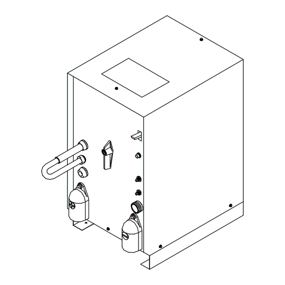
2-5. Dimensions And Weights Dimensions Height 23-1/4 in (591 mm) Width 16 in (406 mm) H 8 Holes H 8 Holes Depth 22-3/4 in (578 mm) 13 in (330 mm) 12-1/4 in (311 mm) 3/4 in (19 mm) 16-1/16 in (408 mm) Front Front 14-29/32 in (379 mm) -
Page 16: Remote 14 Receptacle Information
2-7. Remote 14 Receptacle Information Socket* Socket Information 24 volts ac. Protected by circuit breaker CB2. 24 VOLTS AC 24 VOLTS AC C L N Contact closure to A completes 24 volts ac con- tactor control circuit. 115 volts ac. Protected by circuit breaker CB1. 115 VOLTS AC 115 VOLTS AC Contact closure to I completes 115 volts ac con-... -
Page 17: Placing Jumper Links And Connecting Input Power
2-9. Placing Jumper Links And Connecting Input Power Check input voltage available at site. Jumper Link Label Check label − only one is on unit. Jumper Link Move jumper links to match input power. Line Disconnect Device Select type and size of overcurrent protection using Section 2-8. -
Page 18: Section 3 − Operation
SECTION 3 − OPERATION 3-1. Controls Ref. ST-121 471-F / Ref. ST-186 125 Voltage Range Selector Plug lected by Voltage Range Selector plug. Each Pilot Light position of the switch is a change of 2 volts. Circuit Breaker CB2 Use plug position to select voltage range. If CB2 opens, the 24 volts ac output to the Re- Y Do not change position of Voltage High Range Receptacle... -
Page 19: Section 4 − Maintenance & Troubleshooting
SECTION 4 − MAINTENANCE & TROUBLESHOOTING 4-1. Routine Maintenance Y Disconnect power before maintaining. 3 Months Repair Or Replace Replace Unreadable Cracked Labels Weld Cable Clean Tighten Weld Connections 6 Months Blow Out During Heavy Service, Vacuum Clean Monthly Inside 4-2. - Page 20 SB-119 335-A Figure 4-1. Circuit Diagram For Welding Power Source OM-293 Page 16...
-
Page 21: Section 5 − Parts List
SECTION 5 − PARTS LIST 7 − FIG 5−3 FIG 5−2 − 18 Hardware is common and not available unless listed. ST-121 583-E Figure 5-1. Main Assembly Item Dia. Part Mkgs. Description Quantity Figure 5-1. Main Assembly .. - Page 22 Hardware is common and not available unless listed. ST-121 587-B Figure 5-2. Panel, Front w/Components OM-293 Page 18...
- Page 23 Item Dia. Part Mkgs. Description Quantity Figure 5-2. Panel, Front w/Components (Fig 5-1 Item 19) ....057 608 RECEPTACLE, jack plug yellow (consisting of) .
- Page 24 Item Dia. Part Mkgs. Description Quantity Figure 5-3. Panel, Rear w/Components (Fig 5-1 Item 7) ....081 372 BLADE, fan 9 in 5wg 20deg .
- Page 25 Notes...
- Page 26 Notes...
- Page 27 Warranty Questions? (Equipment with a serial number preface of “KK” or newer) Call 1-800-4-A-MILLER This limited warranty supersedes all previous Miller warranties and is exclusive with no other for your local guarantees or warranties expressed or implied. Miller distributor. LIMITED WARRANTY − Subject to the terms and conditions APT, ZIPCUT &...
-
Page 28: Options And Accessories
Contact the Delivering Carrier for: File a claim for loss or damage during shipment. For assistance in filing or settling claims, contact your distributor and/or equipment manufacturer’s Transportation Department. PRINTED IN USA 1999 Miller Electric Mfg. Co. 9/98...
Need help?
Do you have a question about the Regency 250 and is the answer not in the manual?
Questions and answers