Table of Contents
Advertisement
NC-6000
Compact Two Pockets Currency Discriminator
COPYRIGHT © 2011 Masterwork Automodules Tech Corp Ltd.
All rights reserved. This Document or any part thereof may no, without the prior
written consent of Masterwork Automodules Tech Corp Ltd., be copied, reprinted or
reproduced in any material form including, but without prejudice to the foregoing
and not by way of exception photocopying, transcribing, transmitting or storing in
any medium or translating into any language, in any form or by any means,
including but not limited to, electronic, mechanical, xerographic, optical, magnetic,
digital or other methodology.
Masterwork Automodules Tech Corp Ltd.
11F-3, 3, Park St., Nangang, 11503, Taipei, Taiwan
Service Manual
Document Version 1.0
Oct 1
support@automodules.com
st
, 2012
Advertisement
Table of Contents

Summary of Contents for MA NC-6000
- Page 1 NC-6000 Compact Two Pockets Currency Discriminator Service Manual Document Version 1.0 Oct 1 , 2012 Masterwork Automodules Tech Corp Ltd. 11F-3, 3, Park St., Nangang, 11503, Taipei, Taiwan support@automodules.com COPYRIGHT © 2011 Masterwork Automodules Tech Corp Ltd. All rights reserved. This Document or any part thereof may no, without the prior written consent of Masterwork Automodules Tech Corp Ltd., be copied, reprinted or...
-
Page 2: Table Of Contents
1.3 A ........................5 BBREVIATIONS AND CRONYMS 1.4 C ..........................6 ONTACT NFORMATION CHAPTER 2 NC-6000 OUTLINE ..................... 7 2.1 NC-6000 A ..........................7 LANCE 2.2 S ............................8 PECIFICATION 2.2.1 Functional and Mechanical Specification ..................8 2.2.2 Electrical Specification ........................8 2.2.3 Interface Specification ........................ - Page 3 4.8.3 Detection Level ..........................31 4.8.4 Count Mode Intensity ........................31 4.8.5 Printer Type ..........................31 4.8.6 Hpr Trigger Detection Mode ......................31 CHAPTER 5 NC-6000 PART LIST AND DISASSEMBLY ............32 ..........................32 OOL PREPARATION 5.2 H ............................... 33 OUSING 5.2.1 Side Panel Left and Right ......................
- Page 4 Service Manual – NC-6000 Date: OCT 1 , 2012 (Version 1.0) 5.3.2.2 Keypads ........................56 5.3.2.3 LCD Display ........................57 5.3.2.4 PCB NC6000-UI_IRR Board ................... 57 5.3.3 Stacker Module ........................58 5.3.3.1 Stacker and Reject Pocket ....................61 5.3.3.2 Reject Pocket Stoppers ....................61 5.3.4...
-
Page 5: Chapter 1 Introduction
1.2 Important Safety Precaution • NC-6000 is exclusively for indoor usages only, please do not use or install it outdoor. • Please check the adaptor and power cord periodically to protect from any damages. -
Page 6: Contact Information
Service Manual – NC-6000 Date: OCT 1 , 2012 (Version 1.0) 1.4 Contact Information Masterwork Automodules Tech Corp Ltd. www.automodules.com Address: 11F-3, 3, Park St, Nangang, 11503, Taipei, Taiwan Tel: +886 2 2655 7997 Fax: +886 2 2655 7996 Email: support@automodules.com... -
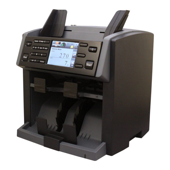
Page 7: Chapter 2 Nc-6000 Outline
Service Manual – NC-6000 Date: OCT 1 , 2012 (Version 1.0) Chapter 2 NC-6000 Outline 2.1 NC-6000 At A Glance Hopper Guide Top Bill Path Open Hopper 3.5 Inch color TFT Control Panel LCD Display Reject Pocket Stacker Pocket Bottom Bill Path Open... -
Page 8: Specification
Service Manual – NC-6000 Date: OCT 1 , 2012 (Version 1.0) 2.2 Specification 2.2.1 Functional and Mechanical Specification Sensors: IR Array, MR, UV Denomination Detection: IR Transmission Dual User Operation: Available Currencies USD, EUR, and up to 5 additional currencies Countable Note Size: 60 X 85 X 0.08mm ~ 100 X 190 X 0.12mm... -
Page 9: Interface Specification
Service Manual – NC-6000 Date: OCT 1 , 2012 (Version 1.0) 2.2.3 Interface Specification 2.2.3.1 Thermal Printer (RS-232) (A) Communication Conditions Item Specification Standard: EIA RS-232C Baud Rate: 9600bps ,38400bps ,115200bps Synchronous Method: Asynchronous Data Format: Start 1 bit Data... -
Page 10: Remote Display
Service Manual – NC-6000 Date: OCT 1 , 2012 (Version 1.0) 2.2.3.2 Remote Display (A) Communication Conditions Item Specification Standard: UART Baud Rate: 115200bps Synchronous Method: Asynchronous Data Format: Start 1 bit Data 8 bits Parity None Stop 1 bit... -
Page 11: System Overview
Service Manual – NC-6000 Date: OCT 1 , 2012 (Version 1.0) 2.3 System Overview Masterwork Automodules Tech. Corp., Ltd Confidential - 11 -... -
Page 12: Chapter 3 Maintenance
Open the bill path. Gently wipe it or dust the bill path with a MA brush or a dry, soft lint-free cloth. If stains remain, moisten a soft, lint-free cloth with water or a 50-50 mixture of isopropyl alcohol and water that does not contain impurities. -
Page 13: Chapter 4 Maintenance Mode
Date: OCT 1 , 2012 (Version 1.0) Chapter 4 Maintenance Mode Maintenance Mode is for testing and maintaining NC-6000 only. Please follow the instruction as below when operating under the mode, or there is a risk to damage the device. -
Page 14: Test Run - Simple Mode
Service Manual – NC-6000 Date: OCT 1 , 2012 (Version 1.0) 4.1 Test Run – Simple Mode To test the feeding process with the four sets of IR trigger sensors in the bill path. 4.1.1 Run – Value List To check the gap adjustment by using the retrieved values. -
Page 15: Run - Wavform
Service Manual – NC-6000 Date: OCT 1 , 2012 (Version 1.0) 4.1.2 Run – Wavform To check the gap adjustment by using the graphic wave formed by the retrieved value. Enter “Run – Wavform” by press the “ ” after selecting on the item. -
Page 16: Test Run - Strict Mode
Service Manual – NC-6000 Date: OCT 1 , 2012 (Version 1.0) The machine counts and the solenoid toggles between reject pocket and stacker. Check the two pockets to make sure that banknote are separated equally in both pockets. *Note: If the Solenoid &Break doesn’t function well, please contact MA. -
Page 17: Run - Wavform
Service Manual – NC-6000 Date: OCT 1 , 2012 (Version 1.0) Once notes proceed, sensors retrieve value and they are showed on the list. • MAX: Value of Tilt shall not over 4. • AVE: Value of Tilt shall not over 2. -
Page 18: Upgrade Mode
*Note: If the Solenoid & Break doesn’t function well, please contact MA. 4.3 Upgrade Mode Using supported devices to upgrade NC-6000. 1. Insert SD card with upgrade firmware into the device. Highlight the “SD” and press “ ” to enter the upgrade mode. -
Page 19: Sd Upgrade
4.3.1 SD Upgrade Before upgrade the SD card. 1. Get a folder with upgrading firmware and database from MA. 2. Put the folder into SD card with the folder name “_SD_Upgrade”. *Note: (1) File system must be FAT32, other type is not supported. -
Page 20: Calibration Mode
Service Manual – NC-6000 Date: OCT 1 , 2012 (Version 1.0) 4.4 Calibration mode Before calibrating sensors. Highlight the option and press “ ” Use “F1” and “F2” key to adjust the dimension value of calibration paper. Note: Dimension value is stated on each calibraiton paper. - Page 21 Service Manual – NC-6000 Date: OCT 1 , 2012 (Version 1.0) Close the Lid, check if the Cal tool is placed properly, no bending. Cal tool is not bowed Move cursor to “2.Ver2-[a] Dark Paper” and double press “ ”. After the screen shows a black arrow beside the dimension value, wait for about 5 seconds.
-
Page 22: Adjust Mg
”. Adjust the value of magnetic sensor by pressing the keys “ ” and “ ”. (from 000 to 128) Note: To adjust the MG value, please contact MA. 4.4.3 Initialization Initializing the sensor. Masterwork Automodules Tech. Corp., Ltd Confidential... -
Page 23: Ir Mode
Service Manual – NC-6000 Date: OCT 1 , 2012 (Version 1.0) *Note: Initialization shall only be executed with indication from MA. Press the “ ” key for the initialization and the display shows “Wait…”. Do not touch any button and wait until the process is finished. -
Page 24: Burn In
Service Manual – NC-6000 Date: OCT 1 , 2012 (Version 1.0) 2. Once a IR sensor is covered, the curve on the display reacts. Users may use hand or supporting items to cover sensors and test the status of IR sensors. -
Page 25: Calibraiton Of Hopper Sensor
Service Manual – NC-6000 Date: OCT 1 , 2012 (Version 1.0) 4.5.4 Calibraiton of Hopper Sensor To calibrate the IR hopper sensor. 1. Highlight the option and press “ ” to enter the burn in mode. 2. Press “ ” to calibrate the hopper sensor. -
Page 26: Machine Running Status
Service Manual – NC-6000 Date: OCT 1 , 2012 (Version 1.0) 4.6.2 Machine Running Status Testing the machine for basic running status under different speeds. Set a preferred speed for testing the device. Sub singler Different speed can be set by press “... -
Page 27: Test Lcd
Service Manual – NC-6000 Date: OCT 1 , 2012 (Version 1.0) 4.6.3 Test LCD Testing the functionality of LCD display. Highlight the option and press “ ” key. The display shows RED, GREEN BLUE continually, then it goes back to the test mode. -
Page 28: Test Encoder
Service Manual – NC-6000 Date: OCT 1 , 2012 (Version 1.0) 4.6.13 Test Encoder Testing the functionality of encoder. Highlight the option and press “ ” key. The motor starts running a certain time. A number of Encoder is shown on the left side of the option. -
Page 29: Machinery Info
Service Manual – NC-6000 Date: OCT 1 , 2012 (Version 1.0) 0: SD card is not inserted. 1: SD card is detected. 2: SD card is not detected well. * In case of 2, Please check if the SD card is completely inserted. -
Page 30: Capacity Of Pockets
Service Manual – NC-6000 Date: OCT 1 , 2012 (Version 1.0) *Note: It’s suggested to use default setting on the device. 4.8.1 Capacity of pockets To change the default capacity of pockets. To change the maximum capacity of banknote for reject pocket. -
Page 31: Detection Level
Service Manual – NC-6000 Date: OCT 1 , 2012 (Version 1.0) 4.8.3 Detection Level Highlight the “Count Mode-Light intensity” and change the level of intensity 0(low) to 3(high) in count mode by pressing “ ”. Note: It’s suggested to use default setting on the device. -
Page 32: Chapter 5 Nc-6000 Part List And Disassembly
Service Manual – NC-6000 Date: OCT 1 , 2012 (Version 1.0) Chapter 5 NC-6000 part list and Disassembly 5.1 Tool preparation Screwdriver (+) Screwdriver (-) Long Nose Plier 7 mm Wrench 3 mm Hex Key 1.5 mm Hex Key Masterwork Automodules Tech. Corp., Ltd... -
Page 33: Housing
Service Manual – NC-6000 Date: OCT 1 , 2012 (Version 1.0) 5.2 Housing Part Name Accessory Code Picture Q’ty Top cover-ONE 3PP02100130041 Paper-Guide (Holder) 3PP52500100170 Paper-Guide-L 3GE40008171010 Paper-Guide-R 3GE40008171020 Gear-14T 3GE00814261100 Rack BK 3NC90800120010 Top cover-TWO 3PP02100130021 Masterwork Automodules Tech. Corp., Ltd... - Page 34 Service Manual – NC-6000 Date: OCT 1 , 2012 (Version 1.0) Banknote guide- L 3PP92110100010 Banknote guide- R 3PP92110100020 Side Panel L 3PP32100040060 Side Panel R 3PP42100040060 Back Cover 3PP12100040010 Lid Back-Frame 3PP22100130010 Masterwork Automodules Tech. Corp., Ltd Confidential - 34 -...
-
Page 35: Side Panel Left And Right
Service Manual – NC-6000 Date: OCT 1 , 2012 (Version 1.0) 5.2.1 Side Panel Left and Right 1. Prepare the machine and all the necessary tools. Left Right 2. Turn the machine to rear side and loosen the two screws (M3x5-Countersunk) on right hand. -
Page 36: Top Cover-One And Two
Service Manual – NC-6000 Date: OCT 1 , 2012 (Version 1.0) 5. Disassemble the Side Panel-R from the machine. *Note: When assembling the side cover, please make sure the plastic cover and metal plate fitted to each other. 6. Repeat the steps 1 to 5 to dismount the Side Panel-L. -
Page 37: Lid Back-Frame
Service Manual – NC-6000 Date: OCT 1 , 2012 (Version 1.0) 5.2.3 Lid Back-Frame 1. Loosen the two screws (M3x5-Countersunk) on the Lid Back-Frame of right sides. 2. Loosen the another two screws (M3x5-Countersunk) on the left side. *Note: When assembling the Lid Back-Frame, please organize the cable of motor baord to prevent damage on the cable. - Page 38 Service Manual – NC-6000 Date: OCT 1 , 2012 (Version 1.0) 2. Disassemble back cover from the machine. Masterwork Automodules Tech. Corp., Ltd Confidential - 38 -...
-
Page 39: Total Assembly
Service Manual – NC-6000 Date: OCT 1 , 2012 (Version 1.0) 5.3 Total Assembly Masterwork Automodules Tech. Corp., Ltd Confidential - 39 -... -
Page 40: Upper Bill Path Module
Service Manual – NC-6000 Date: OCT 1 , 2012 (Version 1.0) 5.3.1 Upper Bill Path Module Part Number Part Name in English Picture Unit 3TP00012030011 feed shaft (12) 3NC51500120010 feed BK frame M4x10-Round head (w/ spring 3SC00040100200 washer) 3SP01150070010 Torsion (1.5-Ø14) - Page 41 Service Manual – NC-6000 Date: OCT 1 , 2012 (Version 1.0) 3NC00800120020 Top Frame 3TP20000030020 feed adjustment fixed M3x10-Round head (w/ spring 3SC00030100200 washer) 3SP31140210010 Compression adjustment (1.4-21) 3TP20000030030 SCREW M8 (P0.5) 3TP10816060010 shaft sleeve (8-16) WA061208KN7000 E-ring (Ø6) 3TP10608030010...
- Page 42 Service Manual – NC-6000 Date: OCT 1 , 2012 (Version 1.0) 3RPA3100220010 Retarding wheel 3SC86030061000 M3x6 hex socket set screw (Nyloc) 3PP52600100180 Feed idler wheel arm holder 3TP00005030030 metal idler wheel 3TP19916010000 single direction bearing holder BEHF0612R01010 Single Direction Bearing 3WA60500217000 E-ring (Ø5)
- Page 43 Service Manual – NC-6000 Date: OCT 1 , 2012 (Version 1.0) M3x6-Round head (w/ spring SC30006M05NW00 washer) S-BNC6000A06 NC6000-M134 3SC52030050200 Ø3×5-Pan 3PP02500100051 Upper Bill Path Plate 3PP82400000140 LED LENS (Top assem) 3RPA3120220060 idler wheel(5-6-22) 3TP00006030021 idler wheel shaft (6) 3SP01060020010 Torsion idler (0.6-Ø3.0)
- Page 44 Service Manual – NC-6000 Date: OCT 1 , 2012 (Version 1.0) 3SC02030080200 Ø3×8-Round head Masterwork Automodules Tech. Corp., Ltd Confidential - 44 -...
- Page 45 Service Manual – NC-6000 Date: OCT 1 , 2012 (Version 1.0) 1. Turn the machine to left side and find the two encoders. 2. Loosen the two screws (M4x6-round head with spring washer) on the encoder. *Note1: Take encoder before...
- Page 46 Service Manual – NC-6000 Date: OCT 1 , 2012 (Version 1.0) 4. Turn the machine to the left side and release the cable from the cable clamp. 5. Disconnect the two cables which are connected to the PCB-Motor board. 6. Turn the machine to the rear side and take off the two plastic e-ring (Ø6) from the shaft of top assembly.
-
Page 47: Upper Bill Path Plate
Service Manual – NC-6000 Date: OCT 1 , 2012 (Version 1.0) 5.3.1.1 Upper Bill Path Plate 1. Turn the upper bill path module and have the sensor side down. 2. Loosen the three screws (Ø3x8-Round Head) to release the ground cables. -
Page 48: Pcb Nc6100-S Board
Service Manual – NC-6000 Date: OCT 1 , 2012 (Version 1.0) 5.3.1.2 PCB NC6100-S board 1. Release the cables from the connecters. *Note: When plugging in the cable on the connecters, please make sure all the pins are well connected on the cable. -
Page 49: Pcb Nc6000-M134 Board
Service Manual – NC-6000 Date: OCT 1 , 2012 (Version 1.0) 2. The LED Len is under the NC6100-IRTE board. 5.3.1.4 PCB NC6000-M134 Board 1. Loosen four screws (Ø3×5-Pan) NC6000-M134 board. 2. The NC6000-M134 board is now free to be removed. - Page 50 Service Manual – NC-6000 Date: OCT 1 , 2012 (Version 1.0) 2. Use a 3mm hex key to loosen the two hex flange (M4×10) 3. Use a 1.5mm hex key to release the screw on the retarding wheel spacer. *Note: When assembling the singler spacer, please use two pcs of milar film to maintein a certain distance between the spacer and the top frame.
- Page 51 Service Manual – NC-6000 Date: OCT 1 , 2012 (Version 1.0) 5. Remove the bearing from the retarding wheel shaft. 6. The retarding wheel is now free to be removed from the module. Masterwork Automodules Tech. Corp., Ltd Confidential - 51 -...
-
Page 52: Control Panel Module
Service Manual – NC-6000 Date: OCT 1 , 2012 (Version 1.0) 5.3.2 Control Panel Module Part Number Part Name in English Picture Unit 3PP02100130030 Top front 3SC16030050200 M3x5-Countersunk S-BNC6000A10 NC6000-IRR 3PP72100000061 hopper sensor holder 3SC02030080200 Ø3×8-Round head Masterwork Automodules Tech. Corp., Ltd... - Page 53 Service Manual – NC-6000 Date: OCT 1 , 2012 (Version 1.0) 3PP72000080150 Front panel 3SC02030080200 Ø3×8-Round head C-L00010 TFT LCD Panel 3NC90800120050 LCD Holder 3PP62000080140 14 rubber button 3PP62000080170 5 rubber button 3RP13400100040 14 rubber button 3RP13400100050 5 rubber button...
- Page 54 Service Manual – NC-6000 Date: OCT 1 , 2012 (Version 1.0) 3ST4NC6000G010 Metal Dome 5 key 3SC02030080200 Ø3×8-Round head 3SC52030050200 Ø3×5-Pan Masterwork Automodules Tech. Corp., Ltd Confidential - 54 -...
-
Page 55: Pcb Nc6000-Ui Board
Service Manual – NC-6000 Date: OCT 1 , 2012 (Version 1.0) 1. Loosen the two screws (M3x5-Countersunk) on the control panel module. 2. Loosen the screws (M3x5-Countersunk) on the both sides of the hopper. 3. Release the ground cable by loosening the screw (M3x6-Rround Head with spring washer). -
Page 56: Keypads
Service Manual – NC-6000 Date: OCT 1 , 2012 (Version 1.0) 3. The control panel assembly is now free to be removed. 4. Turn the control panel to the rear side. 5. Loosen the four screws (Ø3x5-Pan) on the NC6100-UI board. -
Page 57: Lcd Display
Service Manual – NC-6000 Date: OCT 1 , 2012 (Version 1.0) 2. The left and right keypad is now removed. 5.3.2.3 LCD Display 1. Pull out the LCD display from the control panel. 2. The LCD display and LCD holder are removed from the control panel. -
Page 58: Stacker Module
Service Manual – NC-6000 Date: OCT 1 , 2012 (Version 1.0) 5.3.3 Stacker Module Part Number Part Name in English Picture Unit 3PP72100130130 Outlet part 2 3PP82400000080 Led (Outlet part 2) 3PP82100000020 reject sensor light guide 3SC52030050200 Ø3×5-Pan 3SC12030080200 Ø3×8-Countersunk... - Page 59 Service Manual – NC-6000 Date: OCT 1 , 2012 (Version 1.0) 3PP92400020120 Reject stopper 3SP00050080010 Torsion reject (0.5-Ø2.7) 3TP00002030010 Reject shaft (2) 3PP72100130140 Outlet part 1 3OC25390000000 static brush 3NC90602190010 Static Brush Fixed BK C01NN01NN130 Harness - ESD1 3SC12030080200 Ø3×8-Countersunk...
- Page 60 Service Manual – NC-6000 Date: OCT 1 , 2012 (Version 1.0) 1. Lay down the machine and loosen the four screws (Ø3x8-Countersunk) on the bottom of the machine. 2. Release the stacker stopper and stacker static plate from the stacker module.
-
Page 61: Stacker And Reject Pocket
Service Manual – NC-6000 Date: OCT 1 , 2012 (Version 1.0) 5.3.3.1 Stacker and Reject Pocket 1. Loosen the two screws (Ø3x8-Countersunk) ob the both sides of the stacker module. 2. Release the reject pocket plate from the assembly. 3. The reject pocket is removed from the stacker module. -
Page 62: Bottom Conveyor Module
Service Manual – NC-6000 Date: OCT 1 , 2012 (Version 1.0) 5.3.4 Bottom Conveyor Module Part Number Part Name in English Picture Unit 3PP12100130020 Back Lid 3PP22500100031 Bottom Conveyor plate 3TP00007030010 idler wheel shaft-A (7) 3RPA3120220060 idler wheel(5-6-22) 3TP00006030030 idler wheel shaft-B (6) Masterwork Automodules Tech. - Page 63 Service Manual – NC-6000 Date: OCT 1 , 2012 (Version 1.0) 3RPA3120220070 idler wheel(5-6-35) 3WA60500217000 E-ring (Ø5) 3SP02060030010 Torsion idler (0.6-Ø6.8) 3PPA2600100110 Idler Fixed 3SC02030080200 Ø3×8-Round head 3PP62100100150 Back lid connector S-BNC6000A11 NC6000-DTE 3PP52400000130 Led pcb holder (2LED) 3SC52030050200 Ø3×5-Pan 3SC02030080200 Ø3×8-Round head...
-
Page 64: Bottom Conveyor Plate
Service Manual – NC-6000 Date: OCT 1 , 2012 (Version 1.0) 1. Open the back lid. 2. Release the back lid connector from the back lid. 3. Release the E-ring (Ø4) from the both side of shaft 4. The back lid is now removed. -
Page 65: Pcb Nc6000-Dte Board
Service Manual – NC-6000 Date: OCT 1 , 2012 (Version 1.0) 2. Disconnect the indicated cable from the connector. 3. Pull out slowly the bottom conveyor plate. *Note: If it results dificulty when pulling out the bottom conveyor plate, please check if the cable has been released. -
Page 66: Base Module
Service Manual – NC-6000 Date: OCT 1 , 2012 (Version 1.0) 5.3.5 Base Module Part Number Part Name in English Picture Unit OSPSOLRSA32470 Solenoid 3NC50800120121 Solenoid Cover 3PP62500100160 Note Toggler Masterwork Automodules Tech. Corp., Ltd Confidential - 66 -... - Page 67 Service Manual – NC-6000 Date: OCT 1 , 2012 (Version 1.0) 3TP00306130010 Interrupter bar 3PPA2600100120 Shaft sleeve (interrupter) 3NC60800120030 Interrupter Plate 3SC36030060200 M3×6-Round washer M3x6--Rround head (w/ SC30006M05NW00 spring washer) 3PP92600100130 Reject pocket note holder S-BNC6000A13 NC6000-RJP M3x6-Round head w/ spring...
- Page 68 Service Manual – NC-6000 Date: OCT 1 , 2012 (Version 1.0) 3SC52030050200 Ø3×5-Pan (PH#2) M3x10-Round head w/ spring 3SC00030100200 washer (PH#2) 3NCA0300190010 Encoder wheel M4x6-Round head w/ spring 3SC00040060200 washer 3TP00008030050 Kicker roller shaft 3OC27170000000 Aperture spring pin (Ø3x14) 3RPA3100220020...
- Page 69 Service Manual – NC-6000 Date: OCT 1 , 2012 (Version 1.0) 3RPA3100220040 Singler wheel - driver 3WA41050917000 Wave washer (Ø10.5) Flat Washer 3WA01040209000 (Ø10.4×Ø21×1.5t) 3PPA2600100130 Singler wheel fixer S-BNC6000A11 NC6000-DTE 3PP52400000140 Led pcb holder (3LED) 3SC52030050200 Ø3×5-Pan (PH#2) M3x10-Round head w/ spring...
- Page 70 Service Manual – NC-6000 Date: OCT 1 , 2012 (Version 1.0) M3x10-Round head (w/ spring 3SC00030100200 washer) 3NC20800120060 Power BK ED000003F002 AC socket EMI filter C05MH03NN125 Harness - AC_IN C-F00003 3SC12040120200 Ø4×12-Countersunk 3OC04290000100 Wire Holder A S-BNC6000A08 NC6000-COM M3x6-Round head w/ spring...
- Page 71 Service Manual – NC-6000 Date: OCT 1 , 2012 (Version 1.0) 3LB0S20M160000 Timing Belt (160-S2Mx6mm) 3LB0S30M189000 Timing Belt (189-S3Mx6mm) Masterwork Automodules Tech. Corp., Ltd Confidential - 71 -...
-
Page 72: Timing Belts
Service Manual – NC-6000 Date: OCT 1 , 2012 (Version 1.0) 5.3.5.1 Timing Belts Turing the gear (A) and pulling out the timing belt from the gear (B) to release the timing belt 160mm-S2M. Use the same way as the first step to release the timing belt 189mm-S3M from the gears. -
Page 73: Note Toggler
Service Manual – NC-6000 Date: OCT 1 , 2012 (Version 1.0) 2. The reject pocket holder is now removed from the machine. 5.3.5.3 Note Toggler Loosen the screw (M3×6-Round Washer) on the Left Side solenoid interrupter plate and it’s free to be removed. -
Page 74: Kicker Roller Module
Service Manual – NC-6000 Date: OCT 1 , 2012 (Version 1.0) Pull out the solenoid to remove it from the machine. Right Side Release the plastic E-ring and the bearing from the shaft. The note toggler is now free to be removed from the machine. -
Page 75: Pcb Nc6000-Dte Board
Service Manual – NC-6000 Date: OCT 1 , 2012 (Version 1.0) Release the bearing (688zz) from the shaft of kicker roller module. The kicker roller module is now free to be removed. 5.3.5.5 PCB NC6000-DTE Board Loosen the screw (M3x6-Rround Head with spring Left Side washer)on both sides. - Page 76 Service Manual – NC-6000 Date: OCT 1 , 2012 (Version 1.0) Release the cable from the connector. The bill path is now removed from the machine. Loosen the two screws (M3x10-Round Head with spring washer) on the NC6000-DTE board. The NC6000-DTE board is now free to be removed from the bill path.
-
Page 77: Pcb Nc6000-Irtr2 Board And Ir Guide Box
Service Manual – NC-6000 Date: OCT 1 , 2012 (Version 1.0) 5.3.5.6 PCB NC6000-IRTR2 board and IR Guide Box Loosen the four screws (M3x10-Round Head with spring washer) on the NC6000-IRTR2 board. The NC6000-IRTE2 board is now free to be removed from the bill path. -
Page 78: Pcb Nc6000-A Board
Service Manual – NC-6000 Date: OCT 1 , 2012 (Version 1.0) 5.3.5.9 PCB NC6000-A Board The NC6000-A board is on the left side of the machine. Left Side Disconnect the cables from the NC6000-A board. *Note: The following are the positions of cables to the corresponded connecter. -
Page 79: Pcb Nc6000-Motor Board
Service Manual – NC-6000 Date: OCT 1 , 2012 (Version 1.0) 5.3.5.10 PCB NC6000-MOTOR Board The NC6000-Motor board is on the left side of the Left Side machine Disconnect the cables from the NC6000-Motor board. *Note: The following are the positions of cables to the corresponded connecter. -
Page 80: Power Tray
Service Manual – NC-6000 Date: OCT 1 , 2012 (Version 1.0) 5.3.5.11 Power Tray Loosen the two screws (M3x5-Countersunk)on the power tray Pull out the power tray from the machine. *Note: Please organize the cable on the correct position when assembling the pwer tray back. -
Page 81: Impeller
Service Manual – NC-6000 Date: OCT 1 , 2012 (Version 1.0) Cover of Motor A Release the motor cover from the machine. Cover of Motor B Loosen the three screws (M3x6-Round head w/ spring Motor A washer) of the motor. - Page 82 Service Manual – NC-6000 Date: OCT 1 , 2012 (Version 1.0) Loosen the two screws (M3x6-Round head w/ spring washer). The impeller is now removed from the machine. Masterwork Automodules Tech. Corp., Ltd Confidential - 82 -...
-
Page 83: Chapter 6 Trouble Shooting
Service Manual – NC-6000 Date: OCT 1 , 2012 (Version 1.0) Chapter 6 Trouble Shooting 6.1 Definition of Message Codes 6.1.1 Check Bill Path Please open the bill path and check no foreign matter inside. Error with top bill path, please open it and check no foreign matter inside. -
Page 84: Error
6.1.4 Error Please check if the motor error occurs when power on. Please make sure the encoder is working correctly. If the error still occurs, please contact MA. Masterwork Automodules Tech. Corp., Ltd Confidential - 84 -...
Need help?
Do you have a question about the NC-6000 and is the answer not in the manual?
Questions and answers
Can we order a replacement screen and board. Or a front control panel?? Ours has lines running through it, making it difficult to read.