Table of Contents
Advertisement
Quick Links
Advertisement
Table of Contents

Summary of Contents for Feltest PowerStrobe
- Page 1 Manual PowerStrobe Release Date 01/2011...
- Page 2 Viewing of this light by people with photosensitive epilepsy may trigger epileptic seizures. Eye damage may result from direct viewing of the ultraviolet lamp used in this unit. Do Not Operate a PowerStrobe in Explosive Areas CAUTION: Lens may be extremely...
-
Page 3: Table Of Contents
TABLE OF CONTENTS 1 WARNING 4 WELCOME TO THE POWERSTROBE 5 INTRODUCTION External & Internal Trigger Mode Three Intensity Levels Three Flash Rate Ranges Built-in Memory Feature III. OPERATION Internal Mode External Mode PowerStrobe Control Panel Intensity & Flash Rate Range Control... -
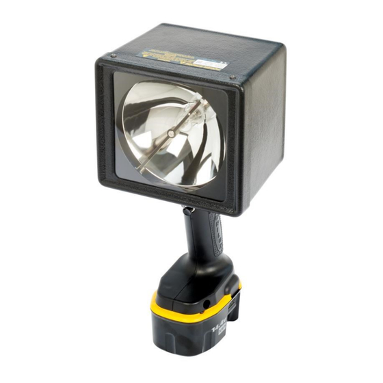
Page 4: Welcome To The Powerstrobe
0.2mm a n d it appears to be stationary since the eye captures and retains only brief visual images. This result makes detailed inspection possible. TRUE COLORS Feltest PowerStrobes emit an excellent white light approaching sunlight that reveals true colors. The light's scientific color temperature is 6500 Kelvin. - Page 5 I I . I N T R O D U C T I O N The PowerStrobe provides narrow beam spot illumination of a flat surface covering 50cm to 100cm. This illuminated area results when using the PowerStrobe at its intended 5 cm to 5m distance.
-
Page 6: External & Internal Trigger Mode
External and Internal Trigger Mode The flash rate of the PowerStrobe can be controlled by an external trigger signal, or the flash rate Up & Down control keys. External mode When the external trigger connector is installed, the internal rate control is disabled and the PowerStrobe will flash synchronously with each external trigger signal. -
Page 7: Three Intensity Levels
Three Intensity Levels The PowerStrobe provides three intensity levels for tailoring the flashlamp brightness to the actual inspection application. The flashlamp intensity is set by using the intensity control key to select 100%, 66%, and 33% levels, depending on the operating flash rate. -
Page 8: Operation
W h en this switch is held in its on pos i t io n , t he PowerStrobe ca n b e o pe r a t e d i n I nt e r n a l o r E x te r na l t r i gg e r m o de . - Page 9 • Fan Fault indicator - illuminates if the internal cooling fan fails to operate. A fan fault condition automatically shuts down the PowerStrobe flash lamp circuit. • Low Battery indicator - blinks when the DC Power Pack requires recharging.
-
Page 10: Intensity & Flash Rate Range Control
• Max Flash Rate = 300 F/S, 18000 F/M Auto-Scale Flash Rate Range Feature The PowerStrobe has a built-in flash rate divider/multiplier feature for maintaining synchronous flash rates throughout the three intensity level selections. This feature is automatically activated whenever the operating flash rate exceeds the max rate for the selected intensity level. -
Page 11: Trigger Input Connector Pin Assignments
I V . E X T E R N A L I N T E R F A C E The trigger input connector is located on the unders ide of the PowerStrobe. Trigger Input Connector Pin Assignments The trigger connector i s a six pin circularDin type. -
Page 12: Specifications
S P E C I F I C A T I O N S DC Power Pack: • Rechargeable NiCd cells • 14.4 VDC nominal voltage • 2.4 Amp hour • DC Power Pack Run Time-See pg.20 Triggering Internal •30 Flashes / Min (F/M) to 18000 F/M •... - Page 13 Energy Output : Energy per flash is set by selected intensity level as follows:. 100% Intensity : 0.85 joules / flash 66% Intensity: 0.43 joules / flash 33% Intensity : 0.28 joules / flash Light Output: 1800 Lux at 4.6 meter 100% intensity, 6000 F/M Flash Duration: 20 microseconds Power into Flash Lamp: 85 watts max...
- Page 14 PHOTOMETRY The isolux chart below shows the PowerStrobe illumination pattern at a target distance Inches Centimeters 24 in 60 cm 18 in 45 cm 12 in 30 cm 6 in 1000 15 cm 2 in 1800 5 cm NOTES: - The distance increments shown above represent displacement from target center...
- Page 15 D C P o w e r P a c k R u n T i m e T he PowerStrobe un it di s pl a y c o nt ai n s a lo w ba tt e r y i ndi c at o r t hat bli nk s w he ne v e r t he D C P o w e r P a c k nee d s re c ha rging.
- Page 16 This is a normal occurrence, and signifies that the DC Power Pack cells have reached the end of their useful life. Replacement DC Power Packs are available from Feltest, order part No. UPN 77-1055. Your DC Power Pack contains nickel cadmium cells. The Environmental Protection Agency considers cadmium to be a toxic material that can do severe damage to the environment.
-
Page 17: Charging The Dc Power Pack
To Charge the DC Power Pack 1. Press the release buttons on the DC Power Pack and firmly pull the Pack out of the PowerStrobe DC Power handle. 2. Connect charger to an appropriate outlet before inserting DC Power Pack. - Page 18 OK. If the new pack charges correctly, then the original pack is defective and should be returned to Feltest for recycling. If the new DC Power Pack elicits the same trouble indication as the original, have charger tested by an authorized Feltest service center.
- Page 19 DC Power Pack after use, avoid placing the charger or pack in a warm environment. CAUTION: Never attempt to open the DC Power pack for any reason. If the plastic housing of the pack breaks or cracks, return the DC Power Pack to Feltest.
- Page 20 · Do not expose charger to rain or snow. · Use of an attachment not recommended or sold by Feltest may result in a risk of fire, electric shock, or injury to persons. · These chargers are not intended for any uses other than charging Feltest rechargeable DC Power Packs.
-
Page 21: Changing The Lamp
IX. CHANGING THE LAMP The PowerStrobe lamp will need to be replaced whenever the lamp reaches its total end of life point. (ie. complete loss of flashing) Before reaching its total end of life point, the lamp may exhibit reduced light output, as well as inconsistent flashing. - Page 22 3. Remove the (2) screws from the Strap, Anode Socket board. Step#3 4. Remove Flash Lamp from the lamp sockets (Anode & Cathode) and install new lamp by reversing the steps of these instructions. Step#4...
-
Page 23: Changing The Filters
X. CHANGING THE FILTERS NOTE: Replace filters when they are completely clogged. 1. Follow steps 1 thru 4 on chapter IX Changing the Lamp. 2. Remove the four (2) screws and (2) Hex Standoff from the casing to remove the lamp reflector from the mounting Support. Step#2 3. - Page 24 5. Loosen (2) Hex nuts and (1) mounting screw to lift out the Blower / Duct Sub-Assembly with the Air Duct Filter Assy. Step#5 Note#1 6. Remove (4) screws holding the Air Duct Filter assembly and replace with new Air Duct filter Assembly by reversing the steps of these instructions.
- Page 25 4.1 CHANGING THE EXHAUST FILTER The exhaust filter (UPN 54-1158) mounted on the casing ( See fig .below) can be removed by loosening two (2) screws that secure the filter holder, thru the outer air exhaust slots . 5.1 Remove the filter holder and filter, and install new Exhaust filter by reversing these instruction steps.
-
Page 26: Spare Parts & Accessories
XI. SPARE PARTS & ACCESSORIES Part No. Spare & Replacement Parts 04-1581 HEAD ASSEMBLY - COMPLETE 04-1580 BLOWER / DUCT SUB-ASSY. 04-1583 DC POWER HANDLE 04-1582 REFLECTOR SUB-ASSEMBLY 04-1598 AIR DUCT FILTER ASSEMBLY 05-1412-1 CONTROL PCB ASSEMBLY 05-1594 POWER BOARD PCB ASSEMBLY 05-1421 EXTERNAL TRIGGER CONN. - Page 27 Lamp Connector Strap, Anode Socket PCB [Anode] UPN 85- Reflector Sub-Assy. Flash Lamp Assembly UPN 05-1595 1251 UPN 04-1582 UPN 45-1047 Window Trim Ring Lens Front Bezel UPN 62-1230 UPN 88-1147 UPN 63-1039 Power Board PCB Assy. Control PCB Assy. UPN 05-1594 UPN 05-1412-1 External Trigger PCB Assy.
- Page 28 Air Exhaust Filter UPN 54-1158 Head Assembly Complete UPN 04-1581 1 Hour Charger [110V or 220V] UPN 56-1040-110 UPN 56-1040-220 14.4 DC Power Pack DC Power Handle UPN 77-105 UPN 04-1583...
Need help?
Do you have a question about the PowerStrobe and is the answer not in the manual?
Questions and answers