
Related Manuals for Campbell NL240


Summary of Contents for Campbell NL240
- Page 1 NL240 Wireless Network Link Interface Revision: 4/15 C o p y r i g h t © 2 0 1 1 - 2 0 1 5 C a m p b e l l S c i e n t i f i c ,...
-
Page 3: Limited Warranty
Limited Warranty “Products manufactured by CSI are warranted by CSI to be free from defects in materials and workmanship under normal use and service for twelve months from the date of shipment unless otherwise specified in the corresponding product manual. (Product manuals are available for review online at www.campbellsci.com.) Products not manufactured by CSI, but that are resold by CSI, are warranted only to the limits extended by the original manufacturer. - Page 4 SCIENTIFIC, INC., phone (435) 227-9000. After an application engineer determines the nature of the problem, an RMA number will be issued. Please write this number clearly on the outside of the shipping container. Campbell Scientific’s shipping address is: CAMPBELL SCIENTIFIC, INC.
- Page 5 • Periodically (at least yearly) check electrical ground connections. WHILE EVERY ATTEMPT IS MADE TO EMBODY THE HIGHEST DEGREE OF SAFETY IN ALL CAMPBELL SCIENTIFIC PRODUCTS, THE CUSTOMER ASSUMES ALL RISK FROM ANY INJURY RESULTING FROM IMPROPER INSTALLATION, USE, OR MAINTENANCE OF TRIPODS, TOWERS, OR ATTACHMENTS TO TRIPODS AND TOWERS SUCH AS SENSORS, CROSSARMS, ENCLOSURES, ANTENNAS, ETC.
-
Page 7: Table Of Contents
7. Configuring the NL240 ..........13 Configuring the NL240 with DevConfig via USB ......13 Configuring the NL240 with DevConfig via Wi-Fi WLAN ....14 Configuring the NL240 with Telnet via Wi-Fi WLAN ...... 14 Configuring the NL240 via RS-232 ........... 15 8. - Page 8 Net Services Tab ................C-12 TLS Proxy Server Tab ..............C-14 TLS Tab ..................C-16 D. Sending a New OS to the NL240 ......D-1 Sending an OS via USB ..............D-1 Sending an OS via Wi-Fi ..............D-1 E. Radio Frequency Emission ........E-1...
- Page 9 Table of Contents Figures 3-1. NL240 with CR800 (powered through CS I/O port) ......2 3-2. LoggerNet setup ................... 4 4-1. NL240 ....................5 4-2. Bridge Mode enabled ................5 4-3. Bridge Mode disabled ................6 5-1. NL240 dimensions ................8 6-1.
- Page 10 Table of Contents...
-
Page 11: Introduction
• Precautions manual. The first time an NL240 is attached to a datalogger and Bridge Mode is • enabled, the datalogger’s memory has to be reorganized to allow room in memory for the IP stack. To avoid the loss of data, collect your data before enabling Bridge Mode. -
Page 12: Physical Setup
Physical Setup Attach an antenna to the NL240’s antenna connector. Using the supplied serial cable, connect the NL240’s CS I/O port to the datalogger’s CS I/O port. Alternatively, power the NL240 through the barrel-connector jack located on the edge of the device. Ensure that the device is powered up by inspecting the Power LED. - Page 13 If a dynamic address is to be used, the network information acquired via • DHCP can be seen on the NL240 tab. (Note that if you have selected a different network than the default network, you will need to press Apply to save this change, then press the Connect button to reconnect to the NL240 and view the network information.)
-
Page 14: Loggernet Setup
In the LoggerNet Setup screen, press Add Root and choose IPPort. Input • the NL240 IP address and port number. The IP address and port number are input on the same line separated by a colon. IPv6 addresses will need to be enclosed in square brackets when specifying a port number. -
Page 15: Overview
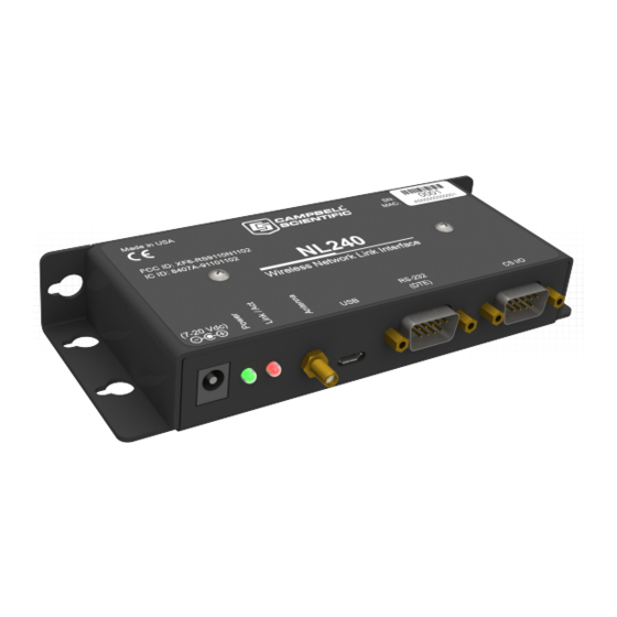
See Section 6, Wi-Fi , for more information. (p. 10) The NL240 includes a CS I/O port and an RS-232 port for communication. A USB device port is used for configuring the NL240 device. FIGURE 4-1. NL240 Bridge Mode Enabled The NL240 can be configured to bridge WLAN and CS I/O communications (see FIGURE 4-2). -
Page 16: Bridge Mode Disabled
CS I/O PakBus router, an RS-232 PakBus router and a CS I/O serial server, or an RS-232 PakBus router and a CS I/O PakBus router. In addition, the NL240 can act as TLS proxy server. The TLS proxy server is independent of other modes. - Page 17 NL240 Wireless Network Link Interface Campbell Scientific’s LoggerNet software is used to communicate with the dataloggers once the NL240 is configured properly and connected to a network. Bridge Mode Allows access to datalogger’s internal IP functionality when a peripheral •...
-
Page 18: Specifications
Power CS I/O or DC Barrel Connector (not USB) 7 to 20 Vdc If you wish to prevent the NL240 from being powered over the CS NOTE I/O port, you can do so by removing a jumper. See Appendix B,... - Page 19 NOTE to turn off power to the Wi-Fi. See the CRBasic help for an example of using the IPNetPower instruction. Note that the IPNetPower instruction is only applicable when the NL240 is configured with Bridge Mode Enabled Operating Temperature Standard: –25 to +50 °C Extended: –55 to +85 °C...
-
Page 20: Wi-Fi
Wi-Fi transmits at frequencies around 2.4 and 5 GHz (the NL240 only uses 2.4 GHz). The high frequency allows fast rates but reduced communication distance. -
Page 21: Rssi
In the NL240’s case, RSSI is the measurement between the NL240 and a wireless access point, a computer in ad hoc or another NL240 in ad hoc. The strength of this link is recorded in dBm (power ratio in decibels) -
Page 22: Antennas
NL240 Wireless Network Link Interface RSSI in the NL240 is measured in a scale between –100 dBm and 0 dBm. The higher the number (i.e. –12 dBm as compared to –72 dBm), the better the connection between Wi-Fi devices. A reliable connection will be maintained if the RSSI reading in the NL240 stays between –85 dBm and –15 dBm. -
Page 23: Configuring The Nl240
DHCP. Operating System Upgrade When a new operating system is sent to the NL240, the red LED will blink repeatedly while the NL240 copies the operating system into its internal flash. -
Page 24: Configuring The Nl240 With Devconfig Via Wi-Fi Wlan
Wi-Fi network it has already been configured to join. The green LED on the NL240 will come on and start blinking once it has joined the network. Once it has successfully obtained an IP address, it will stop blinking and flicker with network activity. -
Page 25: Configuring The Nl240 Via Rs-232
Type edit and press Enter to edit the settings of the NL240. • As each NL240 setting is shown, press Enter to accept the current value • shown in parenthesis. Type a new value and press Enter to change the value. -
Page 26: Wi-Fi Connection
In this configuration, the device will scan for available networks and attempt to join the network (infrastructure or ad hoc) specified by the SSID setting. • Connect to the NL240 in DevConfig (see Section 7, Configuring the NL240 (p. 13) Click on the Wi-Fi tab. -
Page 27: Operational Mode
When the RS-232 or CS I/O port is configured as a PakBus® router, the NL240 can route packets to other devices in the network that it has in its routing table. These are devices that the NL240 has learned about through beaconing or allowed-neighbor lists. -
Page 28: Configuring The Nl240
NL240 Wireless Network Link Interface barrel-connector jack located on the edge of the device. Connect the NL240 to your local wireless network by attaching an antenna to the NL240 antenna connector. Ensure that the device is powered up by inspecting the Power LED. -
Page 29: Loggernet Setup
8.2.1.3 LoggerNet Setup In the LoggerNet Setup screen, press Add Root and choose IPPort. Input • the NL240’s IP address and port number. The IP address and port number are input on the same line separated by a colon. •... -
Page 30: Connect
8.2.2.1 Physical Setup Attach an antenna to the NL240 antenna connector. Using the supplied serial cable, connect the NL240 CS I/O port to the datalogger CS I/O port. Ensure that the device is powered up by inspecting the Power LED. -
Page 31: Loggernet Setup
DevConfig. If it is not connected, the TCP/IP settings will not be displayed. By default, the NL240 uses the datalogger’s CS I/O Interface #2. If connecting more than one NL240 to a datalogger, one NL240 can be configured to use CS I/O Interface #1. This is done by... -
Page 32: Connect
8.2.3.1 Physical Setup Using the supplied serial cable, connect the NL240 CS I/O port or RS-232 port to the datalogger CS I/O or RS-232 port, respectively. The NL240 will be powered if connected via CS I/O. Alternatively, power the NL240 through the barrel-connector jack located on the edge of the device. -
Page 33: Loggernet Setup
In the LoggerNet Setup screen, press Add Root and choose IPPort. Input • the NL240’s IP address and port number. The IP address and port number are input on the same line separated by a colon. • Add a PakBus® Port. -
Page 34: Connect
If the remote server closes the connection due to error, the NL240 will make a best effort to save any data that was in process and re-queue it to be sent on the next successfully-opened TCP... -
Page 35: Modbus Tcp/Ip To Rtu Gateway
NL240 Wireless Network Link Interface 8.2.5 Modbus TCP/IP to RTU Gateway The NL240 can serve as a Modbus TCP/IP to RTU Gateway. It will listen for incoming Modbus TCP/IP connections from a Modbus TCP/IP master client. The port number of the listening connection is specified in the RS-232 Service Port Number setting and is typically set to a value of 502. -
Page 36: Tls Proxy Server
TCP DevConfig link. The TLS Private Key, TLS Private Key Password and TLS Certificate can only be edited/transmitted over a secure DevConfig link (USB or TLS). If the status of the TLS stack is Initialized, the NL240 will NOTE automatically negotiate a secure TLS connection with DevConfig as long as the Use IP Connection option is selected. -
Page 37: Tls Proxy Server Configurations
In Configuration A, the NL240 decrypts TLS traffic and forwards the unencrypted TCP traffic to the datalogger over the CS I/O port. The NL240 is able to “learn” the IP address of the attached datalogger and will open a TCP connection on the “learned”... -
Page 38: Devconfig Tcp Encrypted Communication To The Nl240
IP address. For either configuration, the IP address must not be 0.0.0.0, and it must be unique on the same subnet as the NL240 IP address. For example, if the NL240 IP address is 192.168.5.1 and Subnet Mask is 255.255.255.0, the datalogger address could be set as 192.168.5.2 provided there are no other... -
Page 39: Applications
Working Around Firewalls The NL240 can be used to provide a connection between LoggerNet and a datalogger when both are behind firewalls. The NL240 must be on a public IP address and will act as a common meeting place for all PakBus®... -
Page 40: Configuring The Datalogger
Press Apply to save the changes and then close DevConfig. 10. Troubleshooting This section covers some common problems that might be encountered when using the NL240. This is not comprehensive but should provide some insight and ability to correct simple errors without a call to Campbell Scientific technical support. - Page 41 NL240: IP address: 192.168.0.2, Network Mask: 255.255.255.0 PC: IP address: 192.168.0.3, Network Mask: 255.255.255.0 If you are using DHCP to assign an IP address to the NL240, use • DevConfig to read the IP address assigned to your NL240. This is done through a USB connection to the NL240 while the NL240 is connected to your network (if bridge mode is not being used).
-
Page 42: Revision
NL240. These can be downloaded from our website at www.campbellsci.com. 7. If the NL240 is configured as a CS I/O serial server, verify that any other SDC device attached to the datalogger is using a different SDC address. -
Page 43: Attribution
NL240 Wireless Network Link Interface If running NL240 firmware revision v.4 or greater, you can also type • “eventloga” at the prompt to obtain an ASCII version of the low-level log. Copy and paste the output into a text file. - Page 44 NL240 Wireless Network Link Interface...
-
Page 45: Glossary
Bridge (Bridging, Network Bridge) In the context of this manual, bridging is the act of connecting two network interfaces at the data link layer. The NL240 acts as a semi- transparent bridge passing, without alteration, IP packets between the Wi- Fi and CS I/O ports. - Page 46 Proxy (Proxy Server) A device that acts as an intermediary for IP communications between two clients. In the context of this manual, the NL240 acts an intermediary between two or more clients requiring a secure connection (TLS) and one client requiring an unsecured connection. Communications are encrypted and decrypted as necessary for the two clients to communicate via the proxy.
-
Page 47: Cables, Pinouts, Led Function, And Jumper
The supplied SC12 cable can also be used. A DB9 female null modem cable (such as Campbell Scientific part number 13657) is used to connect the NL240’s RS-232 port to a PC’s RS-232 port. The RS-232 cable should be kept short when using high baud rates. -
Page 48: Usb
Appendix B. Cables, Pinouts, LED Function, and Jumper B.3 USB The USB cable is the supplied USB A to micro B style cable (Campbell Scientific part number 27555). This is used only for device configuration. TABLE B-3. USB Micro-B Function... -
Page 49: Power Jumper
B.6 Power Jumper If you wish to prevent the NL240 from being powered over the CS I/O port, remove the two screws on the top of the NL240, remove the NL240’s top cover, remove the jumper above the red LED and place it so that it is connected to only one post. - Page 50 Appendix B. Cables, Pinouts, LED Function, and Jumper...
-
Page 51: Nl240 Settings
Appendix C. NL240 Settings All of the NL240 settings available from the Settings Editor in DevConfig are described below. C.1 Main Tab Model (read only) Model name. Serial Number (read only) Specifies the NL240 serial number assigned by the factory. - Page 52 Appendix C. NL240 Settings CS I/O IP Interface Identifier When the device is configured to operate in Bridge Mode, the datalogger will address the device using this identifier. The datalogger can address up to two “CS I/O IP” devices. The corresponding CS I/O IP Address settings in the datalogger will control the interface.
- Page 53 Appendix C. NL240 Settings IP Address The IP address uniquely identifies this node on an internet. If DHCP is enabled, this is the IP address obtained from the DHCP server. If DHCP is disabled, a static IP address must be obtained from your network administrator for use with this device.
-
Page 54: Wi-Fi Tab
To help guard against unauthorized access to the NL240, it is password- protected by the Admin Password. This password will be required to gain access to the NL240 via DevConfig over TCP and telnet. If the password setting is left blank, no password is required to access the NL240. After settings are saved, the new password will be in effect. - Page 55 NL240 is configured to “Join an Existing Network”, then enter the SSID of the network to join here. If no SSID is specified, the NL240 will join the strongest open network it finds. If the NL240 is configured to “Create an Ad hoc Network”, then the SSID entered here will be the SSID of the network...
- Page 56 Appendix C. NL240 Settings NOTE This setting affects the transmission power level of the NL240, which may affect the transmission range of the device. This setting does not affect the overall power consumption of the device. Lower Power Mode If Low Power Mode is enabled, then the device will be put into its power saving mode.
- Page 57 If the device takes a moment to join the network or it takes a moment to enter a password, the NL240 may power the Wi-Fi down in the meantime. The smartphone should still be...
-
Page 58: Rs-232 Tab
This is a read-only field that lists the networks available in the area. Information listed for each network is: SSID, RSSI / Signal Strength, Channel, Security. NOTE If the NL240 is creating an ad hoc network, wireless networks in the area may not be displayed. C.3 RS-232 Tab RS-232 Configuration This setting controls which process will be associated with the RS-232 port. - Page 59 RS-232 RTS The NL240 asserts the RTS and DTR lines when doing RS-232 communications. This setting allows the user to disable the RTS line if needed so that it will not be asserted.
- Page 60 This setting specifies the interval, in units of seconds, that will be reported as the link verification interval in the PakBus® hello-transaction messages. It will indirectly govern the rate at which the NL240 will attempt to start a hello transaction with a neighbor if no other communication has taken place within the interval.
-
Page 61: Cs I/O Tab
Appendix C. NL240 Settings RS-232 Modbus Timeout This setting determines how long the MODBUS/TCP to MODBUS/RTU gateway will wait for an answer from the MODBUS slave device(s) attached to the RS-232 port. If no answer is received within the timeout period, the MODBUS/TCP server will reply to the MODBUS/TCP client with error code 0x0B (Target Device Failed to Respond). -
Page 62: Net Services Tab
This setting specifies the interval, in units of seconds, that will be reported as the link verification interval in the PakBus® hello-transaction messages. It will indirectly govern the rate at which the NL240 will attempt to start a hello transaction with a neighbor if no other communication has taken place within the interval. - Page 63 (range 1..65535) PakBus Routes (read only) This setting lists the routes that are known to the NL240. Each route known to the NL240 will be represented by the following four components separated by commas and enclosed in parentheses. The description of each component...
-
Page 64: Tls Proxy Server Tab
Appendix C. NL240 Settings Port Number Specifies a numeric code for the port that the router will use. It will correspond with one of the following: CS I/O RS-232 PakBus/TCP Connection — If the value of the port number is 100 or greater, the connection is made through PakBus/TCP. - Page 65 If the TLS Proxy Forward Physical Port is specified to be the CS I/O port, the NL240 will then open a TCP connection with the logger over the CS I/O port and do unecrypted data transfer with the datalogger.
-
Page 66: Tls Tab
TCP server is uniquely identified by an IP address and a port number. This entry is where the port number of the NL240’s TCP client is set. The datalogger’s TCP server port must be set to communicate on this port number. - Page 67 Appendix C. NL240 Settings TLS Certificate Specifies the public certificate (in PEM format) for the encryption stack. This setting can only be edited/transmitted if the DevConfig link NOTE is considered secure (USB or TLS). If the TLS stack has been initialized, the device will automatically negotiate a secure TLS connection with DevConfig if the Use TCP option is selected.
- Page 68 Appendix C. NL240 Settings C-18...
-
Page 69: Sending A New Os To The Nl240
OK button. 9. The operating system will be sent to the NL240. 10. After the file has been sent, the power LED on the NL240 will blink repeatedly while the NL240 copies the OS into its internal flash. This process takes about 10 seconds. - Page 70 OK button. 11. The operating system will be sent to the NL240. 12. After the file has been sent, the power LED on the NL240 will blink repeatedly while the NL240 copies the OS into its internal flash. This process takes about 10 seconds.
-
Page 71: Radio Frequency Emission
Appendix E. Radio Frequency Emission Changes or modifications to the NL240 not expressly approved by Campbell Scientific, Inc. could void the user’s authority to operate this product. NOTE This equipment has been tested and found to comply with the limits for a Class B digital device, pursuant to part 15 of the FCC Rules. - Page 72 Appendix E. Radio Frequency Emission...
- Page 74 • info@campbellsci.com.cn • info@campbellsci.de www.campbellsci.com www.campbellsci.de Campbell Scientific do Brasil Ltda. (CSB) Campbell Scientific Spain, S. L. (CSL Spain) Rua Apinagés, nbr. 2018 ─ Perdizes Avda. Pompeu Fabra 7-9, local 1 CEP: 01258-00 ─ São Paulo ─ SP 08024 Barcelona...
Need help?
Do you have a question about the NL240 and is the answer not in the manual?
Questions and answers