
Summary of Contents for Simple Water Service 7QCRO
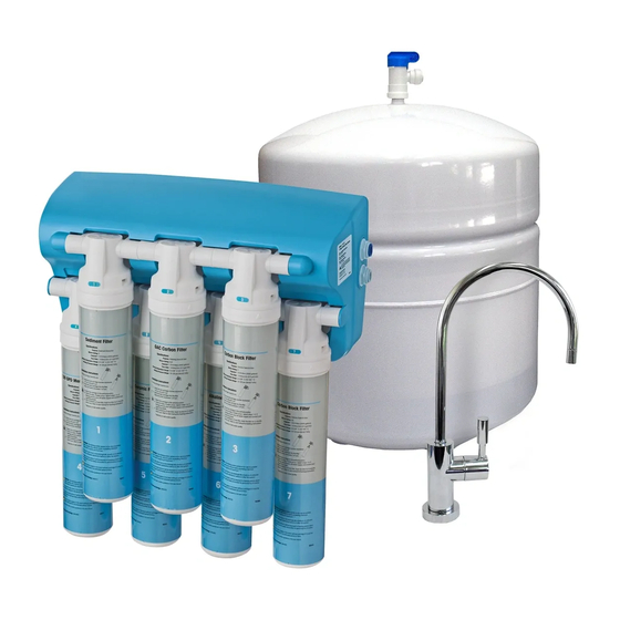
- Page 1 Installation, Operation & Service Instructions with Part List 7 Stage Water Filtration System Improving water, improving life... One family at a time. Model: 7QCRO...
- Page 2 attention Customer: This system is intended for use on potable water supplies or disinfected water containing cysts. Do not use where water is microbiologically unsafe or with water of unknown quality. If bacterial contamination is present, a recognized method of water disinfection is required. Check with your public works department for applicable local plumbing and sanitation codes.
- Page 3 INTRODUCTION Thank you and congratulations on making a smart decision to invest in a 7 Stage Water Filtration System. You have joined an elite group of water enthusiasts who demand only the best when it comes to their health and the health of their family.
-
Page 4: Table Of Contents
Installation, Operation & Service Instructions with Part List 7 Stage Water Filtration System table of Contents Page Specifications and Performance Data Sheet ..............3 Safety Guidelines . -
Page 5: Specifications And Performance Data Sheet
Carbon Block (Stage 7)....Chlorine Taste and Odor Production Rate 1 ....7QCRO 100 gpd(37.8 L/day) - Page 6 Dimensions 16.0” Product Water Storage tanks 6.7” 15.2” 13.7" 17.6” 2.1” 11.5" 2.5” 13.3” Figure 1 Notes Recommended influent Water Characteristic 1. A booster is strongly recommended to improve the reduction of TDS. Higher pressures will help maintain the membrane’s maximum Pressure 40 - 100 psi rejection performance.
-
Page 7: Safety Guidelines
NOTE: The water system contains a replaceable treatment component, critical for the effective reduction of total dissolved solids, and that product water shall be tested periodically to verify that the system is performing properly. SYSTEM SPECIFICATIONS 7 Stage Water Filtration System Item #: 940475 Model #: 7QCRO Item # Stage Filter / Type Specification... -
Page 8: Suggested Installation Equipment
Suggested Installation Equipment Recommended tools 1. Utility Knife 2. Flathead Screwdriver 3. Phillips Screwdriver 4. Center Punch 5. 7/8” Stepped Drill Bit 6. Finish Hole Saw 7. Porcelain Saw 8. -
Page 9: Overview Of The 7 Stage Water Filtration System
Overview of the 7 Stage Water Filtration System Manifold The manifold assembly serves as the functional hub of the water system by directing the flow through each of the system’s main components. Sediment Filter The primary use is to remove sediment from the water. The secondary use is one of insurance against random increase in particulates on normally sediment free water supplies. -
Page 10: Package Contents
Package Contents O UT TEMPLA TE FO R SC REW HO LE PA TTEN 1/4” 3/8” Figure 4 1. -
Page 11: Preparation
Product Information This manual covers the technical aspects of 7QCRO drinking water systems. It is important to read this manual thoroughly so that you can properly apply, install, and service these systems. The substances reduced by this system are not necessarily in the customer’s untreated water. - Page 12 Storage tank Preparation Verify Flow Control Flow Restrictor Location Note: Changing the air pressure will The Water System manifold alter the amount of water comes attached with the elbow stored in the tank. Increasing fitting flow control. the pressure will decrease capacity while decreasing This flow control is attached pressure will increase...
-
Page 13: Installation
Installation The exact placement of the components will vary by installation. Although shown beneath a sink, it may be installed in a basement, crawl space, or in an adjacent cabinet. Regardless of where the system is installed, the flow sequence described by (figure 9) must be observed. -
Page 14: Step 1 Select Component Installation Locations
The following steps will enable you to install the system quickly and orderly. Some variation may be necessary depending on the installation. See page 6 for a check list of tools. typical installations follow this sequence: 1. Select Component Installation Locations 2. -
Page 15: Step 2 Faucet Installation
Step 2 – Faucet installation To simplify its access and installation, we suggest you install the faucet on the rear lip of the sink. It should be evenly positioned with the sink faucet and spray attachment. Should the spray faucet hole not be available for the installation, the sink must be drilled. -
Page 16: Faucet Installation
Faucet Installation 3/8” 1/4” Tubing Tubing Faucet Base (Remove white protective film.) Rubber Washer Split Washer Lock Washer Spacer (Optional) Faucet Adapter Drain Line from Faucet (3/8” Tubing) Drinking Water Line to Faucet (3/8”... -
Page 17: Tubing Connections
Faucet installation Remove white protective film from faucet base. Verify faucet body, metal base, and rubber base washer are in place above sink (Items 1, 3, and 2). Lower faucet into mounting hole and place faucet over hole. Install slotted washer, spacer, faucet washer, and nut onto faucet nipple below sink and snug them up (Items 4, 5, 6, 7 and 8). -
Page 18: Step 3 Install Adapter Valve On Water Supply
Step 3 – install adapter Valve on Water Supply 1. Locate shut off valves on water lines under sink. To iden- tify hot & cold supply pipes, turn on both faucets and let water run. Hot water pipe will be the warmer pipe. Turn off cold water supply valve. - Page 19 Figure 17 1. Install the drain saddle 2. Tighten the clamps with 3. For standard faucets drill a 4. Attach 3/8” tube by slip- valve on to the drain pipe. the help of the two bolts. 1/4”...
-
Page 20: Step 5 Install Reservoir Tank
Step 5 – install Reservoir tank Place the reservoir tank in the location previously selected. Step 6 – install Filter System assembly The mounting bracket contains four mounting slots. The holes are sized to accept #10 round head wood screws (supplied). Some types of surfaces such as particle board or drywall, may require the use of plastic screw anchors or toggle bolts to provide adequate support for the unit. -
Page 21: Step 7 Start Up
Connect System When cutting plastic tubing, use a sharp utility knife. Cut the tubing squarely. See page 7 for cutting and connecting tubing. Please Please connect connect upper upper connection connection 2. Connect 1/4-inch OD plastic tubing 3. -
Page 22: Performance And Technical Information
Performance & Technical Information The performance of the system can be characterized and judged by the quality and quantity of the water produced by the system. By measuring the contaminant removal performance and flow rates of the system, its operating status can be easily evaluated. -
Page 23: Installing A Water System To Service Other Water Using Appliances
Installing the Water System to Service Other Water Using Appliances Pressure, Pressure, Pressure If you are installing a service line from an the Water System storage tank to an appliance with a minimum pressure requirement then you may need to consider the following options so as not to operate below the operating limits of that appliance. -
Page 24: Service And Maintenance
Service and Maintenance Service Schedule To keep the water system operating properly, it is necessary to change the filters and sanitize the system periodically. Typically, this should be done on an annual basis. Service frequency may vary depending on local water conditions. High sediment, chlorine, turbidity, or hardness levels may require more frequent service. -
Page 25: Drinking Water Sanitization Kit (Pn: 42903018)
Drinking Water System Sanitization Kit (PN: 42903018) Preparation 940480 Kit Contents 940481 Place some rags or a towel 940482 940483 below the system as some 158133 water may leak during this procedure. Have a pail 1/4” Tubing handy to drain water into. 115200 7X Blank Cartridges... -
Page 26: Metal Tank Sanitization Procedure
Metal Tank Sanitization Procedure tank Pressure Check 1. Turn off water supply to your water 3. Using a clean eye dropper insert 1/2 1. Turn off incoming water supply system by turning off the adapter teaspoon of hydrogen peroxide or to water system. -
Page 27: Parts Breakdown
CARTRIDGE, SEDIMENT, 7QCRO, 1ST STAGE Filter Stage #1 940478 CARTRIDGE, GAC, 7QCRO, 2ND STAGE Filter Stage #2 940479 CARTRIDGE, CARBON BLOCK, 7QCRO, 3RD STAGE Filter Stage #3 940480 CARTRIDGE, MEMBRANE, 7QCRO, 4TH STAGE Filter Stage #4 940481 CARTRIDGE, CERAMIC, 7QCRO, 5TH STAGE... -
Page 28: Packaging Kit Bom
Packaging Kit BOM O UT TEMPLA TE FO R SC REW HO LE PA TTEN Figure 27 item # Description item # Qty. Drain Saddle 92656 Tank Shut-off Valve PPSV501222W Piercing Saddle Valve 92655... -
Page 29: Stage Water Filtration System Flow Diagram
7 Stage Water Filtration System Flow Diagram inlet Valve Stage 1 Stage 2 Stage 3 out in Auto Shut off Valve Faucet Stage 4 Stage 5 Stage 6 Stage 7 Drain Flow Control tank Figure 28 Refer to page 3 of this manual on the description and function of stages. -
Page 30: Optional Flushing Instructions
Optional Flushing Instructions Flush type Required for Procedure time Single Filter Flush fines from Carbon and See Single Filter Procedure 5 Minutes Ceramic filters. Optional. for each filter table 5 Single Filter Procedure: If flushing Filter Stage # 1, 2, 3, 5, 6 and 7 use part number 940484. If flushing Filter Stage # 4 use Part Number 940485. -
Page 31: Troubleshooting
Troubleshooting Guide If a problem cannot be corrected through the use of this troubleshooting guide please have the following information ready prior to calling the 1-800 number on the back of this manual: • Serial # • Model # table 6 Problem Possible Cause Remedy... - Page 32 Problem Possible Cause Remedy External leakage. a. Tubing not fully seated in fitting a. Check all fittings for tightness. b. Tubing abraded in seal area. b. Recut tubing and redo connection. Overflow at a. Concentrate tubing plugged. a. Clean concentrate tubing of debris. faucet air gap b.
- Page 33 IMPORTANT NOTE: This service record is your warranty. it is your (the customer’s) responsibility to keep the below chart up to date in order to receive the benefitS of the warranty described on the next page. It is the customers’ responsibility to see that the chart below is KEPT up-TO-date.
-
Page 34: Warranty Information
Notes... - Page 36 Limited Lifetime Warranty Subject to the conditions and limitations described below, we warrant its Model 7QCRO 7 Stage Water Filtration Systems (excluding replacement membrane, cartridge and inline filters), when installed in accordance with our specifications, to be free from defects in materials and workmanship under normal use within the operating specifications for a lifetime period provided that our approved filters and TFC membrane service is done in a timely manner as described in this manual, by an authorized dealer and the service record sheet is up to date.
Need help?
Do you have a question about the 7QCRO and is the answer not in the manual?
Questions and answers