Table of Contents
Advertisement
Quick Links
Advertisement
Table of Contents

Summary of Contents for GreenWave Reality Multi-Port PowerNode
- Page 1 PowerNodes User Guide P o w e r N o d e s U s e r G u i d e | i...
-
Page 2: Table Of Contents
Disposing of Your Used Product ......................15 Safety Information ............................ 16 About GreenWave Reality ........................17 Product Specifications ..........................18 P o w e r N o d e s U s e r G u i d e | i i... -
Page 3: Introduction
A PowerNode is a smart outlet adapter that connects your devices to electrical outlets and your GreenWave Reality energy management system. This allows you to monitor and control your devices’ power usage remotely through a Web browser or smart device application. PowerNodes are available with a one-port or multi-port configuration. -
Page 4: Components
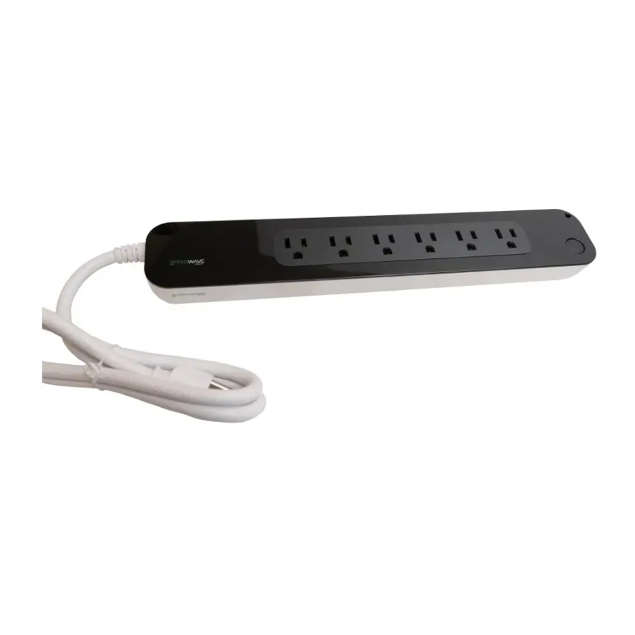
I n t r o d u c t i o n Components One-Port PowerNode PowerNode Plug Plugs into a standard electrical outlet. PowerNode Port Outlet where you plug your device. Activity Indicator and Power Button Displays the status of the connection to the Gateway and controls the power. - Page 5 I n t r o d u c t i o n Multi-Port PowerNode Room Color Selector Specifies the room color associated with the PowerNode. PowerNode Ports Outlets where you plug your devices, PowerNode Power Cord Plugs into a standard Activity Indicator and Power electrical outlet.
- Page 6 All PowerNode ports are powered on. Steady green in center: Some ports on a multi-port PowerNode are powered on while some are off. If you are expecting all ports to be powered on, access your online account to verify your PowerNode and device settings and check their schedule.
-
Page 7: Getting Started
G e t t i n g S t a r t e d Getting Started Before you plug in and install your PowerNodes, verify your Gateway is operating and connected to the Internet. For information on setting up your Gateway, refer to the instructions that came with your Gateway or energy management kit. -
Page 8: Step 2: Set The Room Color
White is suggested for appliances, such as refrigerators or medical equipment that should not be controlled remotely. The white selection locks all ports on a multi-port PowerNode. Black – allows you to manage devices without assigning them to a specific colored number. It •... -
Page 9: Step 3: Sync The Powernode With Gateway
G e t t i n g S t a r t e d You can change the room color for a PowerNode as needed. For example, you might decide that you no longer want to be able to turn the connected device on and off remotely. You could then switch the PowerNode’s room color to the white locked position to prevent control of the attached device remotely. -
Page 10: Step 4: Add Devices To The Powernode
G e t t i n g S t a r t e d During this process, verify that the Gateway activity indicator still displays a clockwise rotating pattern. If not, then the Gateway is not in inclusion mode and you must return to step 3. After a few seconds, the rotating pattern on both the PowerNode and the Gateway stops. - Page 11 G e t t i n g S t a r t e d Perform the following steps: Using your Web browser or smart device, log in to your account. When you log in to your account, you can also access online help for additional information and instructions on working with the Web application.
-
Page 12: Managing Powernodes
M a n a g i n g P o w e r N o d e s Managing PowerNodes You can perform the following tasks: Add or change devices connected to the PowerNode • Move the PowerNode to a different room or change the wheel color •... -
Page 13: Re-Establish The Gateway's Radio Signal
M a n a g i n g P o w e r N o d e s the white locked position. When you change the wheel color, the change is automatically transmitted to your online account so that you see the correct room color when accessed through a Web browser or smart device. -
Page 14: Advanced Z-Wave Tasks
A d v a n c e d Z - W a v e T a s k s Advanced Z-Wave Tasks This chapter is for Advanced Users only. The PowerNodes communicate wirelessly with the Gateway by use of Z-Wave mesh networking, which is a robust connection technology designed for home automation with security and privacy. - Page 15 A d v a n c e d Z - W a v e T a s k s During this process, verify that the Gateway activity indicator still displays a counter-clockwise rotating pattern. If not, then the Gateway is not in exclusion mode and you must repeat step 3. After a few seconds, the rotating pattern on both the PowerNode and the Gateway stops and all bars turn green forming a circle for several seconds.
-
Page 16: Operating Information
O p e r a t i n g I n f o r m a t i o n Operating Information Keep Radio Signals Clear Your Gateway and wireless devices have antennas built-in for radio communication with Internet services and your energy management system. -
Page 17: Disposing Of Your Used Product
Telecommunications Equipment.” DO NOT DISPOSE IN DOMESTIC HOUSEHOLD WASTE. To return unwanted products, contact your local GreenWave Reality office. P o w e r N o d e s U s e r G u i d e | 1 5... -
Page 18: Safety Information
S a f e t y I n f o r m a t i o n Safety Information Caution This device features an internal protection that will disconnect the surge protective component at the end of its useful life but will maintain power to the load—now unprotected. If this situation is undesirable for the application, follow the manufacturer’s instructions for replacing the device. -
Page 19: About Greenwave Reality
A b o u t G r e e n W a v e R e a l i t y About GreenWave Reality GreenWave Reality is an Internet of Things (IoT) software and services company whose 360º solution enables leading brands to quickly and easily deliver new products and services to consumers. -
Page 20: Product Specifications
P r o d u c t S p e c i f i c a t i o n s Product Specifications General Specifications Features 1, 5, or 6 sockets Overcurrent protection Surge protection (UK & NA models only) Radio Frequency Z-Wave Radio Frequency 868.4MHz (EU), 921.4MHz (AS/NZ), 908.4MHz (NA) - Page 21 P r o d u c t S p e c i f i c a t i o n s Specifications by Region Regions AUS/NZ SK/GS Model 1 port - NS24x-I 1 port - NS21x-U 1 port - NS31x-F 1 port - NS21x-G 1 port - NS22x-B x=0;...
- Page 22 1999/5/EC. A copy of the original CE Declaration of Conformity is on file and available upon request for all CE Marked GreenWave Reality products. Please visit www.greenwavereality.com to obtain a copy of the Declaration. The use of such device might not be harmonized throughout EU and EFTA Member States. The Final Integrator of the product shall check that the use of such devices for power node is allowed for placing on the market in any particular Member State.
Need help?
Do you have a question about the Multi-Port PowerNode and is the answer not in the manual?
Questions and answers