Advertisement
Quick Links
GEM-KEYF
R
Transmitter
© NAPCO 2005
GENERAL DESCRIPTION
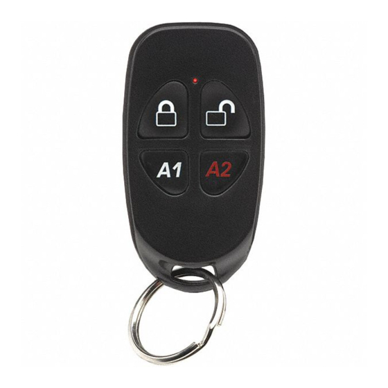
The GEM-KEYF is a multifunction pendant/keychain trans-
mitter compatible with Napco GEM-Series wireless systems. It
serves as an area arm/disarm device with two auxiliary functions,
and may be used as a police panic and/or auxiliary emergency
transmitter. A 3V Lithium coin cell battery (type CR2032) powers
the GEM-KEYF transmitter. A flashing LED indication signals a
low-battery warning to replace the unit.
The GEM-KEYF leaves the factory as a remote area arm/
disarm transmitter with two Auxiliary buttons, A1 and A2. Auxil-
iary functions are selected by programming Key Fob Transmitter
Aux 1 and Aux 2 options: Panic, Auxiliary, or Instant protection.
In addition, any of the panel's Relay Groups may be selected for
controlling garage doors, exterior lighting, or other applications
requiring external relays (RM3000 Relay Modules, optional).
Note: The Aux 1 Button and Aux 2 Button must each be held
down for approximately 2 seconds before the respective signal
will be sent. The LED will light while the unit is transmitting.
ARM
AUX. 1
Factory-Supplied Functions: Arm, Disarm, Aux. 1 and Aux. 2
Low-Battery Check. The batteries are checked automatically
during any transmission. A low-battery condition will cause the
LED to come on and start pulsing for approximately 30 seconds;
a low-battery report will be sent to the receiver.
REQUIRED PROGRAMMING
The following information is required for each unit. Refer to the
instructions for the control panel and keypad in use for detailed
programming information.
• An assigned Key Fob transmitter number
• Area number(s) to which transmitter is applicable
• The 6-digit RF ID code with checksum digit printed on the
transmitter (enter all numbers and/or letters, including leading
zeros, if any)
• Aux-1 option and Aux-2 option
Note: In UL burglar alarm installations:
(1) If the GEM-KEYF is used to arm and/or disarm the sys-
Key-Fob
WI1361 1/05
DISARM
AUX. 2
tem, the control panel must be programmed to provide a
single chirp on arming and a double chirp on disarming. A
listed alarm bell or horn is to be used.
(2) Program the burglary output for all protection devices.
BATTERY REPLACEMENT
1. Remove keyring from the keyring loop.
2. Carefully insert the edge of a small coin in the notch lo-
cated in the bottom right corner of the Key-Fob (near the
keyring loop). Open the case by gently twisting the coin.
Lift off the top cover.
3. With the bottom half of the Key-Fob facing upwards, care-
fully remove the circuit board.
4. On the bottom side of the circuit board, push the battery
out of its metal holder with a sharp pencil. The battery will
slide out of its holder as shown in the image below. Note
the orientation of the battery polarity, with its positive side
up, before fully removing the battery.
5. Replace with a new battery, positive (+) side up, by slid-
ing the battery into its metal bracket. Be certain of battery
polarity before installation.
6. Reassemble the case by first placing the circuit board, bat-
tery side down, into the Key-Fob base. Place the top of
the Key-Fob (with its rubber button/gasket in place) on the
Key-Fob base and press to snap the two Key-Fob pieces
together.
7. Test the Key-Fob operation.
06022
© NAPCO
Battery Replacement: Top View
of Bottom Circuit Board
BUTTON REPLACEMENT
Factory supplied auxiliary buttons can be installed to operate
other items, such as outdoor lights. Install as follows:
1. Open the Key-Fob as per the Battery Replacement in-
structions (above) step 1.
2. With the top cover off, lift and remove the rubber buttons
from the inside of the top
cover.
3. Replace the rubber buttons
with the secondary buttons,
(shown at right) reassem-
bling the Key-Fob in the re-
verse order of disassembly.
4. Test the Key-Fob operation.
Insert pencil and
push battery out of
holder as shown
Advertisement

Related Manuals for NAPCO GEM-KEYF


Summary of Contents for NAPCO GEM-KEYF
- Page 1 • The 6-digit RF ID code with checksum digit printed on the transmitter (enter all numbers and/or letters, including leading zeros, if any) • Aux-1 option and Aux-2 option Note: In UL burglar alarm installations: (1) If the GEM-KEYF is used to arm and/or disarm the sys-...
- Page 2 In no event shall NAPCO be liable for an following the date of manufacture. amount in excess of NAPCO's original selling price of the...
Need help?
Do you have a question about the GEM-KEYF and is the answer not in the manual?
Questions and answers
What does A1 do on the fob?
The Aux 1 (A1) button on the NAPCO GEM-KEYF fob is a factory-supplied auxiliary button that can be used to operate external items such as garage doors or outdoor lighting. It must be held down for approximately 2 seconds before the signal is sent, and the LED will light while the unit is transmitting.
This answer is automatically generated