Table of Contents
Advertisement
Advertisement
Table of Contents

Related Manuals for Samyung Navis 3800

Summary of Contents for Samyung Navis 3800
- Page 1 CAUTION This GPS ChartPlotter is the most advanced Navigation device since ever developed. However a navigation officer of ability should not make a decision, by information from this device only, which might be occurred damages in people’s life and property while sail &...
-
Page 2: Table Of Contents
Contents Chapter 1 : GPS PLOTTER 1. GPS Overview ....................8 Chapter 2 : FEATURES 1. GPS Antenna & Receiver................10 2. DGPS Antenna & Beacon Receiver ............10 3. Main Unit Features & Functions ............11 4. Standard Scope of Supply ............... 13 Chapter 3 : Device &... - Page 3 1.3 User Coast Line ..........................36 1.3.1 Coast Line Display ............................. 36 1.3.2 Coastal Line Drawing ............................36 1.3.3 Coastal Line Save ............................... 37 1.3.4 Coastal Line Load............................... 38 1.3.5 Coastal Line Erase.............................. 39 1.4 Waypoint Data...........................40 1.4.1 Waypoint Display ............................... 40 1.4.2 Waypoint Edit ..............................
- Page 4 3. System ......................63 3.1 Satellite Information ........................63 3.2 Screen Print ............................65 3.3 How to test Keyboard........................66 3.4 How to set up System........................66 3.5 SYSTEM INFO .............................71 4. FISHFINDER (NAVIS 3800F) ..............72 4.1 Screen Speed............................75 4.2 Noise Erase............................75 4.3 Color Erase............................76 4.4 Tx Power Set............................76 4.5 PULSE WIDTH SET..........................77 4.6 COLOR PATTERN SET ........................77...
- Page 5 6. MEDIA(Option) ................... 88 6.1 TV / VTR..............................88 6.2 CAMERA - 1 ............................88 6.3 CAMERA - 2 ............................89 6.4 CAMERA - 3 ............................89 6.5 CAMERA – 4 ............................89 6.6 CAMERA – SCAN..........................89 6.7 MULTI MEDIA .............................89 6.8 MEDIA OFF ............................90 6.9 ETC.
-
Page 6: Chapter 1 : Gps Plotter
1 1 1 1 GPS PLOTTER This chapter provides an overview of the GLOBAL POSITIONING SYSTEM (GPS). -
Page 7: Gps Overview
1. GPS Overview The Global Positioning System is based on a radio navigational system using satellites. An unlimited number of users are provided with accurate three-dimensional positions. This 24/7, worldwide coverage, is available under any weather condition. GPS can provide two-dimensional and three-dimensional position information. 3D positioning is mostly used in aircraft or other applications requiring latitude, longitude and altitude. -
Page 8: Chapter 2 : Features
2 2 2 2 FEATURES This chapter provides Features of NAVIS GPS Plotter. GPS Antenna & Receiver DGPS Antenna & Beacon Receiver Main Unit Features & Functions Standard Components... -
Page 9: Gps Antenna & Receiver
1. GPS Antenna & Receiver GPS Antenna Type : All-weather Micros trip patch antenna Power Supply : Receiver Module Size & Weight : 102 x 65mm (+150mm mounting bar) 0.2kg Receiver Receiving Frequency : 1575.42 ± 1MHz Receiving Architecture : 16 channel Multiple Tracking Receiving Channel : 16 channel Receiving Code... -
Page 10: Main Unit Features & Functions
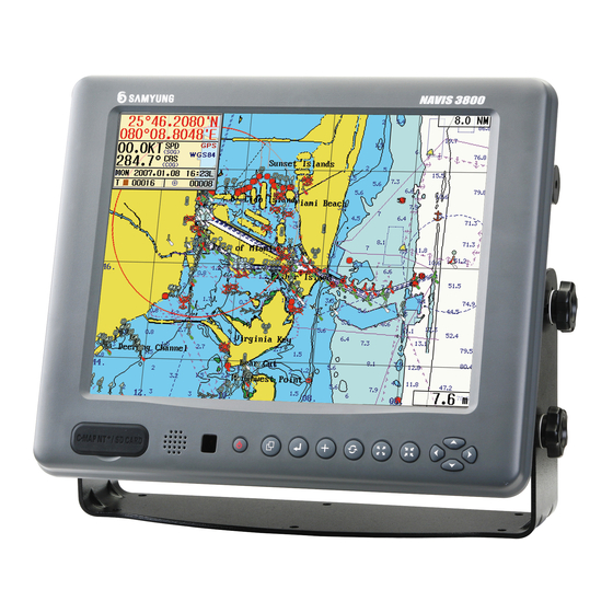
3. Main Unit Features & Functions Main Unit Features : 15inch Resolution : 1024 x 768 Electricity Power : 12V to +35V DC Appox. 40VA Size & Weight : 415 x 345 x 123, 5.9kg Operating Condition Temp. : Antenna = -40℃ ~ +70℃ Main Unit = -15℃... - Page 11 Ownship, Zoom in/out Alarm : Arrival Alarm, Course Break, Anchor Alarm, Boundary Geodetic Datum : Selectable Datum in worldwide Navigation data input/output format : Output/Input (Other brand’s equipment available) SAMYUNG, FURUNO, JRC, NMEA0183(IEC 61162) Calendar Display : The Solar Calendar...
-
Page 12: Standard Scope Of Supply
4. Standard Scope of Supply NAVIS GPS Plotter (with Fish Finder) Name Specification Q’ty Remark Main Unit NAVIS 3800 / NAVIS 3800F GPS Antenna SAN-60 Antenna Cable RG-58C/U 10/20m DC Cable SQ 0.75 X3P Spare Fuse Spare Fuse 3A = 1EA, 7A = 1EA Install. -
Page 13: Chapter 3 : Device & Display
3 3 3 3 Device & Display This chapter provides Device & Display about GPS Plotter. Display Device Remote Controller Power ON/OFF Menu Plotter Display... -
Page 14: Display Device
1. Display Device C-User, C-Map card Slot •C-User card slot (Left) : User Data Load/BackUp •C-Map card slot (Right) : Load C-Map chart •SD card slot Power •Power ON/OFF Diplay Menu & move to sub menu Select, Input, Excution •Select Mark/Track/Erase/Watch /Sunken Vessel, Banks Direction Button •Move a chart to 4 ways and... -
Page 15: Remote Controller Button
2. Remote Controller Button Fish Finder Low/High POWER Select Low/High Frequency Power ON/OFF Depth Range Change Depth Range GAIN/STC Adjust GAIN/STC D.MODE “Man Over Board” Switch Plotter & Fish Finder .Select Menu CNVT .Input Data .Insert Event .N/S, W/E switch mark/Erase .+/- switch .Waypoint, Reverse-Route Navigation... -
Page 16: Power On/Off
3. Power ON/OFF Power ON Press Power OFF Press ) and hold approximately 2 sec. -
Page 17: Menu
4. Menu 1. NAVIGATION SET 1. DATA 1. TRACK DATA 2.SET 2. MARK DATA 2. ALARM SET 3. OWN SHIP SET 3. USER’S LINE 4. CURSOR SET 4. WAYPOINT DATA 5. ROUTE DATA 5. SHIP TRACKING 6. DISK FORMAT 6. SIMULATION 7. -
Page 18: Display Mode
5. Display mode Able to choose a wishable display mode by ( Display mode change at [Plotter Display Only] Plotter Navigation Display mode change at [Plotter/Fishfinder Display] Plotter Plotter/Fishfind Fishfinder Navigation CAUTION Always power OFF when removing or inserting C-Map card... - Page 19 GPS Plotter Display C-MAP Plotter Display...
- Page 20 Definition Description Ownship Latitude Latitude position of ownship’s Ownship Longitude Longitude position of ownship’s Ownship Speed Present Ownship’s Speed, SOG(Speed of Ground) Ownship Course Present Ownship’s Course, COG(Course of Ground) GPS status If no GPS or DGPS signal, Displays "Not-Ready" If GPS is received "GPS", and DGPS is received "DGPS"...
- Page 21 Day/Night Mode in Plotter Display The brightness and transparency can be adjusted when ( ) button is pushed in plotter or plotter/fish finder screen. Also ( ) button is pushed, the day/night display mode can be switched as following.
- Page 22 Navigation Display In Navigation Display (Press ( )), You can see Ownship’s position, Speed, Bearing in full screen which is helpful for your sailing.
- Page 23 Fish finder Combo Display & Fish finder Display...
-
Page 24: Chapter 4 : Operating Instruction
4 4 4 4 Operating Instruction This chapter provides Operating Instruction in NAVIS series. DATA SYSTEM FISH (Fishfinder : NAVIS 3800F) Media(Option) -
Page 25: Data
1. Data Track Data 1.1.1 Track Set Use this function to set the Vessel’s navigation Track. Total track capacity is 20,000 points. When the point is over 20,000, it is deleted previous point one by one. [1.DATA] [1.TRACK DATA] [1.SET] Set the below items used by Direction, Figuers, ) button. -
Page 26: Track Clear
[ Ref. ] ☞ ☞ ☞ ☞ TRACK save [ON] / [OFF] set Select『[ON]』to be saved and drawn current TRACK line, Select [OFF]』not to be saved and drawn TRACK line. ☞ ☞ ☞ ☞ Adjusting TRACK memory interval The smaller figures of time/distance, The more accurate TRACK 1.1.2 Track Clear Use this function to erase the TRACK line of the Vessel. -
Page 27: Track Save
After selecting below TRACK CALC, Press 1. ALL TRACK : Calculate all memory TRACK 2. COLOR : Calculate each color memory TRACK 1.1.4. Track Save Use this function to save TRACK DATA to selected device while Vessel navigates. [1.DATA] [1.TRACK DATA] [4.SAVE] ☞... -
Page 28: Track Load
[ Ref. ] ☞ ☞ ☞ ☞ In using a new C-User card, you must use it after making a initial disc once. ( ☞ Refer to '1.6 DISK FORMAT' ) How to save/call Track by transmitting data The function that is saved into other equipment by using external input/ouput terminal How to set up from Data TX unit [1.DATA] [1.TRACK DATA]... -
Page 29: Track Erase
After selecting file name, Press Once you load the saved TRACK file, any previous TRACK drawn on the screen will be erased. How to save/call Track by transmitting data The function that is saved into other equipment by using external input/ouput terminal How to set up from Data TX unit [1.DATA] [1.TRACK DATA]... -
Page 30: Mark Data
1.2 Mark Data 1.2.1 Mark Select Use this function to select which MARK type to show on the screen. There are 21 unique MARK types. [1.DATA] [2.MARK DATA] [1.SELECT] Select MARK & its color using by Direction key & On the screen, Use ( ) to select MARK. -
Page 31: Mark Clear
Select the position of MARK to append, Press 1.SHIP POS : Append MARK at current Ownship’s position. 2.LAT/LON : Append MARK at indicated Latitude/Longitude position. In a selection [2. LAT/LON], after input the value by direction button & number button, convert button, then press ) button. -
Page 32: Mark Save
Press ) button after select [Mark Clear]. 1. ALL MARK : Clear all MARK 2. SHIP POS : Clear Mark on own-ship’s position. 3. COLOR : Clear MARK in color 4. LAT/LON : Clear MARK in a value of Lat/Lon In a selection『[4.LAT/LON], after input the value by direction button &... -
Page 33: Mark Load
After input 4 digits of file name by using Direction button, ( ) button or number button and ☞ then Press ) button. ( Numbers can be possible only in file name) After select things to be saved and then, press ) button. -
Page 34: Mark Erase
After selecting file name, Press However, be advised that the MARK into a current plotter screen is deleted when call the saved MARK file at that time. How to save/call Mark by transmitting data The function that is saved into other equipment by using external input/ouput terminal How to set up from Data TX unit [1.DATA] [2.MARK DATA]... -
Page 35: User Coast Line
User Coast Line 1.3.1 Coast Line Display Displayed a coastal line drawn by a user into a Plotter screen. In setting『ON』, the coastal line is displayed in a function of '1.3.2 User’s Line Drawing' in advance. [1.DATA] [3.USER’S LINE] [1.DISPLAY] After select [ON] / [OFF]』button by using a direction button and press ) button. -
Page 36: Coastal Line Save
into a Plotter screen. After mover the coordinates cursor to the position of line drawing start by using a direction button and press ) button, then, after move the cursor to a point to be connected and press ) button. Then, the coastal line is keeping connection. In order to jump the coastal line up to another point, not drawing a coastal line connected, after move the cursor to a point of start, press ) button. -
Page 37: Coastal Line Load
[ Ref. ] ☞ ☞ ☞ ☞ In using a new C-User card, you must use it after making a initial disc once. ( ☞ Refer to '1.6 DISK FORMAT' ) How to save/call Coastal Line by transmitting data The function that is saved into other equipment by using external input/ouput terminal How to set up from Data TX unit [1.DATA] [3.USER’S LINE]... -
Page 38: Coastal Line Erase
How to save/call Coastal Line by transmitting data The function that is saved into other equipment by using external input/ouput terminal How to set up from Data TX unit [1.DATA] [3.USER’S LINE] [3.SAVE] After input file [COM PORT] name(0001~9999), How to set up from Data RX unit [1.DATA] [3.USER’S LINE] [4.LOAD]... -
Page 39: Waypoint Data
Waypoint Data 1.4.1 Waypoint Display Function to mark the waypoint that the user registered into a Plotter screen. In setting『[ON], the waypoint is marked in a function of '1.4.2 Waypoint Edit' in advance. [1.DATA] [4.WAYPOINT DATA] [1.DISPLAY] After select [ON] / [OFF]』button by using a direction button and press ) button. -
Page 40: Waypoint Save
10 unit. Input a LAT/LON of the waypoint by using a direction button, number button, convert button ) button. Select Mark & Mark’s color by direction key & ) respectively, Input name by figure & direction key ( ), Press ). -
Page 41: Waypoint Load
☞ Insert things to be saved. ( Possible to omit when using Internal ROM & COM PORT) After input 4 digits of a file name by using a direction button, ( ) button or number button ☞ and then, press ). -
Page 42: Waypoint Erase
Insert save device to load saved file. ☞ Possible to omit when using Internal ROM & COM PORT) Select a storage tool into [Storage Select]. After select a file name and press ) button. However, be advised that the waypoint into a current plotter screen is deleted when call the waypoint file at that time. -
Page 43: Route Data
☞ Insert the device that has files to be erased. ( Possible to omit when using Internal ROM) Select a storage tool having a file to be deleted from [Storage Select]. After select a file name and then press ) button in order to show [Do you want to erase ?] and select『[YES] / [NO]. -
Page 44: Disk Format
Press ) goes to waypoint list edited already, Select waypoints to be route navigation , Press Move cursor down to the second waypoint by , Press ) goes to waypoint list , Press ) to edit. If press buttons, the waypoint to be registered into a route can be shown with a 10 unit. -
Page 45: Seabed Symbol
Insert C-USER card for a format After insert C-USER card, press ) button. It takes around 5 minutes for a format. [ Ref. ] ☞ ☞ ☞ ☞ In case of not available a Disc format 1. In case of self-damage in a Disc itself. - Insert a new Disc. 2. -
Page 46: Program Update
[ Ref. ] ☞ ☞ ☞ ☞ Display ‘Calendar' on the screen 1. Navigation or Plotter screen, Press ), and Select [7.CALENDAR]. 2. Move to wishing date to see by using direction buttons. Program Update Able to replace the plotter program in a main after call the newest plotter program saved into a storage tool. - Page 47 After select 'FROM' number of the left and then, press ) button. '0000' number shows an own-ship’s position and '001~999' is belongs to the registered waypoints. After select 'TO' number of the right and then, press ) button. [ Ref. ] ☞ ☞ ☞ ☞ Select 'Waypoint Navigation' used by ) button .
-
Page 48: Route Navigation Set
☞ Refer to 'Chapter 3 - 5. ■ GPS Plotter Display' ) In order to Navigation Cancellation, move [2.SET] [1.NAVIGATION SET] [4.EXIT WPT/RTE/ANCHOR] and press ) button ☞ or press ( ) button. ( Refer to ‘2.1.4 EXIT WPT/RTE/ANCHOR (Navigation Cancellation) ) [ Ref. - Page 49 The red line is shown from a current position to a first route position and the rest positions registered into a route navigation is shown with a bright-grey line. The Lat/Lon, distance, direction, estimated time, approach speed and navigation time of the navigating route point are ☞...
-
Page 50: Anchor Set
is set up. In this procedure, if press ( ) button once more, the CURSOR is started from a last waypoint of the registered route-navigation so that you can use this function in order to add a new waypoint into a route-navigation. In order to Navigation Cancellation, move [2.SET] [1.NAVIGATION SET]... -
Page 51: Exit Wpt/Rte/Anchor (Navigation Cancellation)
If the vessel breaks away from a range of anchor alarm, the alarm sounds and the red circle blinks in order to advise of the vessel’s break away from the range. For 'ANCHOR ALARM', move [2.SET] [1.NAVIGATION SET] [4.EXITWPT/RTE/ANCHO R] and press ) button or press ( ) button. -
Page 52: Alarm Set
2.2 Alarm Set 2.2.1 Arrival Alarm In using Waypoint Navigation and Route Navigation, this function is designed to create an alarming once the own ship enters into the radius distance of the preset final destination. [2.SET] [2.ALARM SET] [1.ARRIVAL ALARM] ) button to select [ON] / [OFF]. -
Page 53: Anchorage Alarm
) button to select [ON] / [OFF]. In selecting [ON], use the number buttons to input the derailment alarming range (0.01 ~ 9.99). The course derailment range is indicated in blue line, the left window in the bottom shows the derailment distance. -
Page 54: Water Depth Alarm
underwater cables are installed. [2.SET] [2.ALARM SET] [4.SEA-CABLE ALARM] Press ) button to select [ON] / [OFF]. 2.2.5 Water Depth Alarm This function is to provide an alarming for the operators when it senses any specific water depth within the preset alarming range through the transducers. It is available to input 1m ~ 999m. [2.SET] [2.ALARM SET] [5.DEPTH ALARM]... -
Page 55: Ais Alarm
) button to select [ON] / [OFF] and the signals of fish school as [Low], [Mid], [High]. 2.2.7 AIS Alarm After input own ship data at the ‘2.3 Own Ship Set’, AIS alarm will activate when another vessel comes thru within a own ship radius in AIS screen. [2.SET] [2.ALARM SET] [7.AIS ALARM]... - Page 56 Use the directional buttons, ) button, ) button to set up every items shown below. Setup Items Input Range Description 1.AUTO CENTER ON/OFF To indicate that the own ship is in the very center of the display all the time. 2.SHIP MARK Large/Small...
-
Page 57: Cursor Setup
1. In case the vessel speed is low : In case vessel speed/Direction fluctuate, increase the value more. 2. In case the vessel speed is high : Set up the smoothing low and vessel speed/Direction changes fast. <Illustration of smoothing value> Spd. -
Page 58: Ship Tracking
Use the directional buttons ) buttons to select the size, color, shape, and line. 1.CURSOR SIZE : Small / Big 2.CURSOR COLOR : Red / Green / Blue 3.CURSOR SHAPE : Thick / Thin 4.CURSOR LINE : OFF / ON ON - Press button to have the plotting cursor in blue color linking to the current position of the own ship. -
Page 59: Edit
Press ), Select『ON/OFF』. ☞ ☞ ☞ ☞ [ Ref. ] EQUIPMENT REQUIRED FOR TRACK OF SHIP POSITON SRG-2050D, SRG 1150D/1250D, DSC VHF(STR-580D/680D/6000A) 2.5.2 EDIT It is available to input SHIP ID, SHIP NAME, CALLING INTERVAL that will be used for the function. -
Page 60: Etcetera Set
) button to set up [ON] / [OFF] to be used for Simulation. 1.PLOTTER : Plotter Simulation [ON] / [OFF] 2.FISH : Fish-finder Simulation [ON] / [OFF] Etcetera Set User can set up any additional functions on SYSTEM and Plotter. [2.SET] [7.ETC. - Page 61 Miscellaneous Input Range Description Setup Items 1. DISTANCE UNIT NM/KM/MM Select the distance unit on the Display. NM: Nautical Mile (1NM = 1,852 m) KM: Kilometer (1KM = 1,000 m) MM: Land Mile (1MM = 1,610 m) 2. MAGNETIC VAR. True/Magnetic True North differs slightly from Magnetic E00.0°...
-
Page 62: System
3. System 3.1 Satellite Information This is to set up the related information on GPS and DGPS necessary for navigation. It is basically similar to DGPS(Differential GPS) but it also provides the more preciseness of position information to decrease the position differentiation, through receiving the position correction signal from a separate standard correction station located on land. - Page 63 Satellite Info. Input Range Description Item 1.Initial Pos. LAT: 90° N User can set up the information on the own ship 90° S position. LON: 180° E ~ 180° W Ex) When cannot receive GPS, DGPS signal, the information on the current position of own ship can be input.
-
Page 64: Screen Print
Screen Print This function is to print the plotter/Fish finder screen [2.SCREEN PRINT] [3.SYSTEM] Following sections can be selected by using direction buttons and Output Setting Input Description List Range 1.Start Printing Used when a user wants to print current screent. 2.Printer Select HP-PCL Available for “HP-PCL”... -
Page 65: How To Test Keyboard
How to test Keyboard Users can make a self-test to see if the remote works okay. [3.SYSTEM] [3.KEYBOARD TEST] Whenever each button is pressed, it is normal if the button is conversed on the screen. If not, it is judged abnormal. How to set up System Users can set up Input/Output ports used for system, AIS, memory, map, language in use etc. - Page 66 This is to set up the map to be shown on the Range screen. Available SAMYUNG : In SAMYUNG Chart, , Select Depth Unit. C-MAP : In selecting『C-MAP, the unit to be used can be selected. Empty Level : In selecting『C-MAP, the level of the map appearance can be selected.
- Page 67 AIS Setup This is to show on the plotter display the ship together with the information received from AIS, such as Ship Name, MMSI numbers, Lat/Log, SOG, COG. Each ship has her own MMSI number, which is 9-digit ID, assigned and the first 3-digit numbers mean MID (Country Code) which tells her nationality or area.
- Page 68 Details on AIS-Mounted Ship NAME : Ship Name C.SIGN : Call Sign MMSI : Maritime ID IMO.NO : IMO number DRAUGHT : Draught S-TYPE : Ship Type DEST. : Destination NAV. : Current Navigational Status LAT. : Latitude LON. : Current Longitude of Ship : Speed : Course : Heading...
- Page 69 the sub-menu on the screen that shows Ship Name, MMSI, Speed(SOG). Select the ship information of AIS to be displayed on the screen, then press button. Use the directional buttons to select [3.TARGET COLOR-1], then press ) button to input the target color of AIS. Press the number buttons to input MID(or country code) for the target to be set up on the screen, then press ) button.
-
Page 70: System Info
[Note] ☞ ☞ ☞ ☞ It is advised that users normally should not PVI-1/PVI-5 work on setting up as the default value is set. 2.PLOT-MODE LCD-640-Norm/ To set up the Plot model of SYSTEM LCD-640-Auto LCD-640-Norm : Plot Mode for normal use LCD-640-Auto : Plot Mode used with SAMYUNG autopilot system... -
Page 71: Fishfinder (Navis 3800F)
4. FISHFINDER (NAVIS 3800F) GPS chart plotter with fish-finder To see the display of GPS chart plotter with fish finder, press ( Depth Fish Finder High Freq./Low Freq. Screen set up ) to choose Low/High/Dual Freq. display in order. Press How to change F/Finder screen size on the plotter screen Press ( )to select plotter with F/Finder screen... - Page 72 Display for fish-finder only To see the Fish Finder screen only, Press ( ) on the Plotter/F.Finder screen DEPTH AUTO SET F/Finder High Freq./Low Freq. Set up Press ) to select High Freq./Low Freq./Dual Freq. in order. Press ( ) on the Plotter/F.Finder screen or Fish Finder screen RANGE SET : Depth is deeper (Max.
- Page 73 How to shift Line & Homing magnification screen Press ( ) to shift Line & Homing magnification screen in order Line magnification range set up (Press to change the range 『 『 『 『 2.5m/5m/10m/20m/40m/80m』 』 』 』 in order) (Press to change the range in the opposite order as above)
-
Page 74: Screen Speed
Screen Speed A function to adjust a screen moving speed [4.FISH] [1.SCREEN SPEED] Select one of [Stop], [Low], [Mid], [High], [X 2] by using direction cursor and press ). Normally you may set [High]』. Noise Erase To erase an interfacing signal occurs periodically or temporally is shown as noise on fish-finder display. -
Page 75: Color Erase
4.3 Color Erase Clear a color for noise and response for unnecessary school of fish step by step. It helps to recognize of big fish group with distinct display. [4.FISH] [3.COLOR ERASE] Select one of [Off], [Low], [Mid], [High] by using direction cursor and press Tx Power Set To adjust a transmitting output of supersonic wave transmitted from transducer. -
Page 76: Pulse Width Set
PULSE WIDTH SET In response to range of depth and transmitting times, adjust transmitting power by LOW and HIGH about automatic adjustment of pulse width. [4.FISH] [5.PULSE WIDTH] Select [Low], [High] and then press COLOR PATTERN SET Select a color to show a fish group and three colors available. [4.FISH] [6.COLOR PATTERN] Select [Pattern 1], [Pattern 2], [Pattern 3] and then press... -
Page 77: A-Scope Set
A-SCOPE SET A-scope on or off [4.FISH] [7.A-SCOPE SET] Select [ON], [OFF] and then press ETC SET To set a draft (water-depth adjustment), water temperature display/offset and frequency. [4.FISH] [8.ETC. SET] You are able to set following item by direction cursor, number button and ) button. -
Page 78: Weather Fax
System Input Range Description Information List 1.Draft Setting 00m ~ 20m Calculate distance from water surface to transducer on vessel bottom and input the distance value. This value is a criteria line. 2.Water Display a water temperature. Temperature This function only works with a vessel which has a water Setting. -
Page 79: Broadcast Set
5.1 BROADCAST SET Available to receive weather broadcasting by reservation for fax receiving information such as time, SPD/IOC, save, printout, operation and reserve seven channels in total. [5.FAX.] [1.BROADCAST SET] Select wishing channel (CH) and input reserve receiving time. And then ☞... -
Page 80: Receiving Set
Select printing set and printer type by using direction cursor and ) button. 1. PRINTING SET: ON/OFF 2. PRINTER SET HP-PCL: For ink-jet color printer KSSM: Normal dot printer Thermal: Thermal paper roll type printer 【 【 【 【 NOTE】 】 】 】 ☞ ☞ ☞ ☞ The printer should be powered-on when Print is being “ON”. -
Page 81: Viewing Data
5.4 VIEWING DATA To see a fax screen, press ) and go to [5.FAX] [4.VIEWING DATA] [5.FAX.] [4.VIEWING DATA] 5.4.1 Fax Screen Layout and Menu Receiving lamp is flicker in case of receiving fax data. Printer record record CH SPD/IOC Sync-Mode view Recv-Mode... -
Page 82: Spd/Ioc
Go to [CH] and then press ) to select channel number. 5.4.3 SPD/IOC This function is to accord transmitting station that transmits fax-recording data with SPD/IOC. Consisting of 60, 90, 120 and 240 unit, SPD is the speed, which draws dots on the horizontal screen per minute. -
Page 83: Sync-Mode
5.4.4 Sync-Mode 1) AUTO / +00 This function is to synchronize the black bar (synchronizing line) on weather fax screen. AUTO: The bar automatically lines up in vertical. +00: To adjust the incline of the black bar. If the value is increased to positive direction, the bar will be inclined from right to the left. If the value is increased to negative direction, the bar will be inclined from right to the left. -
Page 84: Recv-Mode
5.4.5 Recv-Mode Available to set Auto, Manual receiving mode and broadcasting receiving status (Recv: Start to record, Stop: Stop to record) for weather data from station. 1) AUTO (Receiving mode in auto) Record a weather data while broadcasting only and not available to record after broadcasting done. -
Page 85: Printer
5.4.6 Printer The function is to print on the paper, simultaneously receiving the weather data with fax. In case of ON , it enables to print weather data out on the plotter screen. The printer should be powered ON』. Go to [Printer] and then press ) to select『ON/OFF』. -
Page 86: View
5.4.8 View Available to see a fax record saved according to '5.4.7 SAVE' and also a fax record in reverse. 1) To see saved fax record Go to on [View] and then press ). It shows a direction button in right bottom of screen. CTR button: Available to print current fax screen out if press ( ) on remote control. -
Page 87: Media(Option)
6. MEDIA(Option) 6.1 TV / VTR 6.2 CAMERA - 1 This function is to see the screen from camera. Connect the camera cable to plotter and you can see the screen from the camera on the plotter [6.MEDIA] [2.CAMERA-1] [Note] The function setup of Camera1~Camera 4 is the same. -
Page 88: Camera - 2
6.3 CAMERA - 2 6.4 CAMERA - 3 6.5 CAMERA – 4 6.6 CAMERA – SCAN Camera scan function is available and it enables the pictures from each camera to plotter screen. [6.MEDIA] [6.CAMERA-SCAN] 【Note】 In the [9.ETC. SET], users should set the value in [7.CAMERA SCAN] to use this function. -
Page 89: Media Off
6.8 MEDIA OFF This function is to stop all the function in Media menu. [6.MEDIA] [8.MEDIA OFF] 6.9 ETC. SET In case media function is used, video input, format, size, brightness, contrast, volume, camera scan function can be set up here. [6.MEDIA] [9.ETC. -
Page 90: Chapter 5 : System Maintenance & Diagnosis
5 5 5 5 System Maintenance & Diagnosis This Chapter describes a Maintenance and Diagnosis for NAVIS Series. System Maintenance and Repair. Diagnosis... -
Page 91: System Maintenance And Repair
1. System Maintenance and Repair It is essence to have a routine maintenance and troubleshooting for the equipment for keeping its performance in a normal condition. Maintenance and troubleshooting means periodical check up the system, software up-grade including following items. Item Contents Check up whether Connector and terminal at the rear of the unit is... -
Page 92: Appendix
Appendix This Chapter describes the appendix related to the operation of the unit. Appendix 1. Weather fax receiving frequencies and time table Appendix 2. Description of Weather Map Appendix 3. Geodetic Datum Appendix 4. PACKING LIST Appendix 5. Installation Drawings... -
Page 93: Appendix 1. Weather Fax Receiving Frequencies And Time-Table
Appendix 1. Weather Fax receiving frequencies and time-table (Far East Area) When in use with When in use with 27MHX, SSB(-1.6KHz) Receiver Station Receiving Fr Station Receiving Fr Japan JMH Japan JMH 3622.5 3620.9 7795.0 7793.4 13988.5 13986.9 Time to Observation Revolution Weather Contents... - Page 94 Frequency Frequency Station Time Contents Station Time Contents (KHZ) (KHZ) 10000.0 3622.5 Tokyo 10000.2 7795.0 Japan NO.1, 10000.4 13988.5 TEST JAPAN 10000.6 3365 10000.8 5405 10000.5 Tokyo 9438 5755 NO.2, 14692.5 7535 JAPAN Darwin, 18130 10555 AUSTRALI 4316 15615 8467.5 18060 JMSA &...
- Page 95 Frequency Frequency Station Time Contents Station Time Contents (KHZ) (KHZ) 2422.5 2122 4250 4802.5 6454 9440 Orcadas, Pearl 8195 9455 USA, ORKNEY Harbor, 8818 13862.5 NORFOLK 9983 16398 (US NAVY) 11147 16400 21785 4379 4382 5037.5 Armada de 13525 7770 Chile, 22070 9982.5...
- Page 96 Frequency Frequency Station Time Contents Station Time Contents (KHZ) (KHZ) 4642.5 5850 Skamlebae 5945 9360 Oslo, 8057.5 13855 NORWAY GREENLA 11097 17510 Helsinki, 8018 2780 GREENLA FINLAND 6970 2815 3875 7589.4 5355 DAKAR, 13669.4 Moscow,U 7750 DENEGAL 19752 10980 5420 15950 Kenitra, 9875...
-
Page 97: Appendix 2. Description Of Weather Map
Frequency Station Time Contents KHZ) 4526 4526.5 5127 Cairo, 9043 EGYPT 10123 10560 17365 4930 7405 7510 Episkopi, 9851 CYPRUS 13496 15490 19680 Appendix 2. Description of Weather Map Speed Wind Dir. (25kt) Temp.(20° C) Pressure(20036hPa) Changed value c.weather 3hr ago Dew point Past Cloud Status... - Page 98 Symbols Foggy ≡ Fog Snow Rain A shower Rain Weather Sudden Sea Ice Hail Sleet Symbol Snow Snowstorm Thunder A storm Lightning Typhoon Thunderstorm A front A cold front A warm front Symbol An occluded front A static front...
-
Page 99: Appendix 3. A Geodetic Datum
Appendix 3 A geodetic datum 000. WGS84 051. GB36_WALES 102. OLDHAWAII66 001. KOREA(TOKYO) 052. GUAM 103. OLDHAWAII66_KAUAI 002. AABD_BARAIN 053. HJORSEY 104. OLDHAWAII66_MAUI 003. AABD_SAUDI 054. HK63 105. OLDHAWAII66_OAHU 004. ADDN_BURKINA 055. HUTZUSHAN 106. OLDHAWAII_KAUAI 005. ADDN_CAMEROON 056. INDIAN 107. OLDHAWAII_MAUI 006. -
Page 100: Appendix 4. Packing List
Appendix 4 Packing List NAVIS 3800 / 3800F NAVIS 3800 / 3800F(1/2) Item External Feature Dimension Q’ty CHK Remark NAVIS 3800 NAVIS 3800F NAVIS Main Unit CODE 3800 / 3800F ACC-PLOT-012 Mounting CODE ACC- Bracket PLOT-012 Ø6mm × 20 CODE... - Page 101 NAVIS 3800 / 3800F(2/2) Item External Feature Dimension Q’ty CHK Remark REM-330 CABLE x1 12 REMOCON CODE REM-330 SCREWx2 201B OPTION NAVIS 13 Transducer CODE 201B 3800F ONLY 14 C-MAP Card OPTION CODE C-MAP C-USER C-USER OPTION CODE C-MAP- Card...
Need help?
Do you have a question about the Navis 3800 and is the answer not in the manual?
Questions and answers