
Related Manuals for touch bionics i-limb

Summary of Contents for touch bionics i-limb
- Page 1 Clinician Manual Part number: MA01140: Issue No. 1, April 2013...
- Page 2 This document provides instruction for prosthetists in the fitting and servicing of the i-limb ultra revolution and should be read in full prior to fitting. It is highly recommended that the use of this manual is made in conjunction with instruction from a clinician experienced in upper limb and myoelectric prostheses.
-
Page 3: Table Of Contents
Digit Configuration Digit Installation Thumb Installation 5. Covers Cover Options Donning the i-limb skin active Cover Doffing the i-limb skin active Cover Donning the i-limb skin natural Cover Doffing the i-limb skin natural Cover Wear and Care Guidelines 6. biosim... -
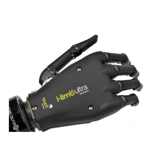
Page 4: I-Limb Ultra Revolution
1.2 Prosthesis Overview The i-limb ultra revolution is available in either black or neutral colors, as well as small or medium sizes. The hand serial number is positioned proximal to the base of the thumb on the connection plate. - Page 5 Motorized Digit Knuckle Palmar Fairing Motorized Thumb On / Off Switch 5 of 57 Part number: MA01140: Issue No. 1, April 2013...
-
Page 6: Socket
2.0 Socket 2.1 Control Sites Figure 1. Electrode Options One option for control of the i-limb ultra revolution is electrodes. There are two electrode options available for use with the i-limb ultra revolution, compact electrodes (fig. 1) or remote electrodes (fig. - Page 7 (see Page 6). Please contact Touch Bionics to order modified electrodes. Coupling Piece Assembly Insert the castelation ring (coupling piece) into lamination ring and turn until seated.
- Page 8 Battery Placement Use Velcro™ to position the batteries on the pre-prepared flat surfaces to prevent distortion. Battery Placement for a Long Residual Limb Consideration of battery placement is particularly important in longer sockets. The shape of the inner socket must also be considered.
- Page 9 2.3 Charge Port Placement Assembly It is important to provide sufficient space for the charge port between the inner and outer sockets. The charge port should be positioned so that it is unaffected by forces running through the socket to prevent damage. Create a drill hole of 8.0mm through the inner surface of the prosthetic frame.
- Page 10 2.4 Battery Options Two battery options are available for the i-limb ultra revolution, both of which have been specifically designed to meet the power requirements of the hand. Battery selection should be based on available space within the socket fabrication, shape of the residual limb and the expected level of use.
-
Page 11: Battery Installation
The battery with DC connector and battery with switch block connector are shown. Only Touch Bionics batteries are approved for use with the i-limb ultra revolution. Use of alternative batteries will invalidate the warranty. 2.6 Battery Installation... - Page 12 When the switch block is used in combination with a wrist rotator 2.5mm D.C. Socket Wiring Schematic for 1300mAh Low Profile the switch block will simultaneously turn off the i-limb ultra Battery with D.C. Socket revolution and the electronic wrist rotator.
- Page 13 2.7 Battery Charging Fully charge the battery prior to fabrication. This may take up to 2 hours. The i-limb ultra revolution should only be charged using the Touch Bionics charger supplied. During charging turn the hand to the OFF position and remove the prosthesis from the residual limb.
-
Page 14: Wrist
See section 3.4 and 3.5 respectively for FlexWrist and Multi-flex Wrist fitting information. 3.2 Quick Wrist Disconnect (QWD) The QWD is supplied by Touch Bionics. Disconnection of the i-limb ultra revolution fitted with a QWD from the socket is completed as follows: Connecting the i-limb ultra revolution using the Ensure the i-limb ultra revolution is switched off. - Page 15 Test the connection is fully engaged with a slight rotation. Disconnecting the i-limb ultra revolution using the QWD Ensure the i-limb ultra revolution is switched off. Support the i-limb ultra revolution in the palm of the hand. 15 of 57 Part number: MA01140: Issue No. 1, April 2013...
- Page 16 3.3 Wrist Disarticulation The wrist disarticulation is fabricated directly into the socket frame and then attached to the i-limb ultra revolution by the following steps: Disconnect the Palm Fairing from the i-limb ultra revolution chassis by unscrewing the screw in the palmar surface using a T10 Screwdriver (supplied).
- Page 17 Remove the Wrist Disarticulation and feed the power cable through. Align the slots and slide the Wrist Disarticulation plate onto the WD Lamination Plate at base of the i-limb ultra revolution ensuring it is firmly engaged. Secure the Wrist Disarticulation to the WD Lamination Plate using the T10 screw and T10 Screwdriver supplied.
- Page 18 Palm Fairing. Loosen the WD Lamination Plate Screw from the Wrist Disarticulation plate. Slide the Wrist Disarticulation off the base of the i-limb ultra revolution. Separate the i-limb ultra revolution from the Wrist Disarticulation, drawing the Basket cable through the Wrist Disarticulation.
- Page 19 The control switch for locking is located on the medial / lateral portion of the wrist and is covered by the flexible wrist sleeve. (See i-limb ultra revolution multi-flex data sheet for more information on the Touch Bionics website: www.touchbionics.
-
Page 20: Adjustments
2, 3, 5 and 6. Sizes 2 and 3 contain a small motor, while sizes Digit Small Medium 5 and 6 contain a larger motor. The standard digit configuration of the small and medium sized i-limb ultra revolution is outlined Thumb in the table. Index Middle... - Page 21 4.3 Thumb Installation The i-limb ultra revolution is only compatible with a Touch Bionics’ i-limb ultra revolution thumb. To exchange a thumb ensure the correct size has been selected.
- Page 22 Disconnect the palmar fairing using the T10 screwdriver to loosen the palmar T10 screw. Gently move the palmar fairing to the ulnar side to allow access to the exposed T10 screw at the base of the thumb. Using the T10 Screwdriver access the screw from the medial to lateral direction to loosen.
- Page 23 If there is resistance while tightening the screw check for cross threading by removing and re-inserting the screw. Touch Bionics recommends T10 Screwdriver PL177001 for use with all T10 screws in the i-limb ultra revolution. 23 of 57 Part number: MA01140: Issue No. 1, April 2013...
-
Page 24: Covers
The back of the glove is smooth to allow the hand to easily move through sleeves of clothing. The i-limb skin natural cover is designed to be close to natural human anatomy. A color swatch is available to select the closest color match between the user’s natural skin color and the color of... - Page 25 Pull the i-limb skin active cover over the hand to the wrist. Individually maneuver the fingers of the i-limb skin active cover over the digits until they are fully aligned.
- Page 26 5.3 Doffing the i-limb skin active Cover There are two ways to position the i-limb ultra revolution to doff the active skin cover. The first way is to manually position your i-limb ultra revolution. The 4 fingers should be fully open and the thumb closed with a 15mm space between thumb and index finger.
- Page 27 This will help the covering slide onto the extended i-limb ultra revolution digits. There are two ways to position the i-limb ultra revolution to don the natural skin cover. The first way is to manually position your i-limb ultra revolution. The 4 fingers should be fully open and the thumb closed with a 15mm space between thumb and index finger.
- Page 28 Note: When using the i-limb natural cover, adjustments may be required in biosim to ensure that digit alignment during functional tasks is not sacrificed. Contact your clinician or Touch Bionics with questions regarding these adjustments.
- Page 29 Slide the covering gently up and over the thumb and continue over the digits. Remove the covering entirely by continuing to gently draw the fingers of the cover, off the digits and off the i-limb ultra revolution. 29 of 57...
- Page 30 ® or Ivory ® The nails of the i-limb skin natural cover are made of silicone recommended. Clean the cover with medical grade rubbing and cannot be polished or painted as this will damage the cover. alcohol once a week to help with disinfection.
-
Page 31: Biosim
“connect” must now clicked for the connection to be made, this will take approximately 15 seconds. If there is more than one i-limb device within range of the Blue- tooth receiver then a box will appear listing all devices by serial number. -
Page 32: User Information
Control strategy details the choice and information around the range of control options as well the logging of user information. Features allows the set-up of the i-limb ultra revolution by linking triggers with grip patterns and gestures. Training provides access to the training suite and a selection of games to improve overall hand control. -
Page 33: Middle 5
If graph the gains are set to their maximum or minimum, then the user may find it very difficult to control the i-limb ultra revolution. Rewind History View Saved Zoom Out •... - Page 34 6.3.2 Control Strategy The control page provides access to control strategy settings. Control strategy is the method by which the i-limb ultra revolution responds to the input channels. While superior control of the i-limb ultra revolution is possible with a dual site strategy, it is...
- Page 35 Graph showing good separation between input signals, however the blue, closing signal is flat lining at the top of the graph – proportional control of the hand is diminished. Reduce the gain setting on closing input. Graph showing low signal strength. Encourage patient to increase signal strength, increase electrode gain if the patient is unable.
- Page 36 In the top right hand of the opening control screen the Device information box will indicate the i-limb ultra revolution serial number. An option exists to swap input channels if the prosthesis has been wired incorrectly; in addition an option is provided for adding a wrist rotator and to enter battery type.
-
Page 37: Ring
6.3.3 Features Click on the features icon to enter the features suite. The feature page provides access to all available features and associated changes. Features are the actual movements of the hand and triggers are the muscle action used to create the movements. - Page 38 Additional Grip and Gesture Options Thumb Park Continuous Thumb Park Quick all four fingers remain open and switch off, all four fingers remain open and switch only the thumb will move. off, for 1.5 seconds the thumb will close and then automatically return to an open position.
- Page 39 Additional Features Toward the bottom right of the screen the additional Global Options box can be used to give access to Vari-grip / pulsing, Natural Hand, Auto-grasp modes, and rotate thumb on exit. Vari-grip/pulsing: this mode provides additional grip force when the closed signal is sustained for the amount of time selected (default 0.5 seconds).
- Page 40 Natural Hand: this feature returns each digit to a position which can be preset by the user. The default setting for activation is 30 seconds, this can be customized between 2 and 60 seconds. Auto-grasp: this feature enables the user to counter a false open signal during grasping.
- Page 41 Co-contraction is the creation of quick simultaneous open and closed signals. Co-contraction may be customized if a patient has difficulty with activation within the default time. The default detect time is set at 80ms and can be customized between 10 and 250ms. Require Stall Open: You have the option to require a hold open before a co-contraction can be detected.
- Page 42 Step 2: Perform co-contraction to get 4 successful attempts. Step 3: After 4 successful attempts, biosim tells you the value and will automatically update i-limb ultra revolution. Double impulse (two quick uninterrupted open signals) the impulse duration is the period of time that the impulse is above the threshold.
- Page 43 Step 2: Perform impulses to get 4 successful attempts. Step 3: After 4 successful attempts, biosim tells you the value and will automatically update i-limb ultra revolution. The graph shows a failed double impulse attempt. The double open signals are strong and within the preset impulse period, however the presence of the blue, closed impulse disrupts the signal.
- Page 44 The graph shows a failed double impulse attempt. The double open signals are sufficiently strong, however the impulses are too far apart to be identified as one signal. Both impulses are recog- nised as individual open signals. Encourage the patient to activate their muscle signals closer together, with less relaxation time between each impulse.
- Page 45 6.3.4 Training The training suite contains a variety of short training exercises aimed at developing control of the i-limb ultra revolution. The opening screen highlights the series of exercises which can be selected individually and in any order. Both open and closed signals can be practiced.
- Page 46 Strength Only focuses on generating a smooth strong muscle signal without concern for the opposing muscle signal. This exercise helps to strengthen the muscles and improve endurance. Speed Only focuses on generating quick, strong muscle signals. Do not be concerned about the opposing muscle in this exercise. Strength and Separation focuses on generating a smooth, strong muscle signal while isolating the opposing muscle.
- Page 47 Simply click on the Health Check icon and the health check will begin. The i-limb ultra revolution will then go through a series of movements as each digit is checked, the process will run for approximately 8 seconds and provide basic feedback on completion of each check.
- Page 48 Options to refresh and reset, along with saving and illustrating the data are also provided. This analysis is very useful when reviewing usage and reliance on the various features of the i-limb ultra revolution. Total runtime will display the total about of time the i-limb revolution has been used.
-
Page 49: Support Information
Always turn off the hand when not in use. Aim to charge the battery each day after use. Replace the battery every 12 months. Ensure i-limb ultra revolution is serviced every 12 months 49 of 57 Part number: MA01140: Issue No. 1, April 2013... - Page 50 Check if the digit operates correctly using the Hand Health Check in biosim operate Exchange with an alternative working digit from same or different i-limb ultra revolution and re-check. If replaced digit works, contact Touch Bionics Hand stops halfway during...
- Page 51 Only approved Touch Bionics accessories and tooling may be used with the i-limb ultra revolution. • replace the battery If utilizing an i-limb ultra mutli-flex wrist, the hand should be • do not re-use locked if carrying an object. •...
- Page 52 Touch Bionics shall under no circumstances whatsoever be liable to the patient or any other party as a result of or in connection with a patient with an i-limb device driving a motor vehicle.
-
Page 53: User Information
8.1 User Details Provision of the following information will enable easy identification of your prosthesis, should it be returned to customer service. Please forward to Touch Bionics as per the contact information on the back page of this manual. User Name:... -
Page 54: Appendix
Hazardous Area Classification The i-limb ultra revolution device is not intended for use outside the boundries of the environments listed below. The customer or user of the i-limb ultra revolution device should assure that it it not used in such environments... -
Page 55: Component Compatibility
General Safety 1.1 The i-limb ultra revolution device is an electrical device, which under certain circumstances could present an electrical shock hazard to the user. Please read the accompanying user manual thoroughly and follow directions stated in the manual to assure maximum safety during charging and operation. - Page 56 Each device has a guaranteed unique id number example: 0001:2012 The unique serial number for i-limb ultra revolution devices is a “R” with a 4 digit alpha / numeric number. The year of manufacture of the device is then added.
-
Page 57: Warranty
Touch Bionics reserves the right to credit, repair or replace an “in-warranty” i-limb ultra revolution as its option. If required, replacements will be new products. The wearer shall report any defect claim to Touch Bionics directly or to the facility that provided the i-limb ultra revolution immediately upon discovering the defect, and, in any event, within the warranty period. - Page 59 Third party products and brand names may be trademarks or registered trademarks of their respective owners © Copyright 2013 Touch Bionics Inc. and Touch EMAS Ltd. All rights reserved. Issue No. 1, April 2013 Part number: MA01140...
Need help?
Do you have a question about the i-limb and is the answer not in the manual?
Questions and answers