
Related Manuals for Oliver NC

Summary of Contents for Oliver NC
- Page 1 Walker, Michigan, U.S.A. 49534-7564 USER’S OPERATING AND INSTRUCTION MANUAL MODEL 690-NC2 STEAM CONVECTION OVEN 0690NC2-S20000-CV...
-
Page 2: Table Of Contents
690-NC2 INDEX Section Description Document No. Page No. SAFETY INSTRUCTIONS ------------------------------- 0690S20040 --------------------- 1-1 DESCRIPTION/SPECIFICATIONS -------------------- 0690S20041---------------------- 2-1 Description -------------------------------------------------------------------------------------- 2-1 Physical Specifications----------------------------------------------------------------------- 2-1 INSTALLATION / SETUP -------------------------------- 0690S20042 --------------------- 3-1 Inspection --------------------------------------------------------------------------------------- 3-1 Location Selection ---------------------------------------------------------------------------- 3-1 Sealing Oven to Mounting Surface ------------------------------------------------------- 3-1 Oven Setup ------------------------------------------------------------------------------------- 3-2 Electrical Connection ------------------------------------------------------------------------- 3-2 Water Connection ----------------------------------------------------------------------------- 3-4... - Page 3 690-NC2 INDEX (Continued) Section Description Document No. Page No. REPLACEMENT PARTS SECTION ELECTRICAL SUB PANEL ------------------------------ 0690S20050 --------------------- 9-1 Drawing ----------------------------------------------------------------------------------------- 9-1 Parts List --------------------------------------------------------------------------------------- FRONT PANEL & OTHER PANELS ------------------ 0690S20051 -------------------- 10-1 Drawing ---------------------------------------------------------------------------------------- 10-1 Parts List -------------------------------------------------------------------------------------- 10-2 DOOR ASSEMBLY ---------------------------------------- 0690S20052 -------------------- 11-1 Drawing ---------------------------------------------------------------------------------------- 11-1 Parts List -------------------------------------------------------------------------------------- 11-2...
-
Page 4: Safety Instructions
690-NC2 SAFETY INSTRUCTIONS WARNING VARIOUS SAFETY DEVICES AND METHODS OF GUARDING HAVE BEEN PROVIDED ON THIS OVEN. IT IS ESSENTIAL HOWEVER THAT THE OVEN OPERATORS AND MAINTENANCE PERSONNEL OBSERVE THE FOLLOWING SAFETY PRECAUTIONS. IMPROPER INSTALLATION, MAINTENANCE, OR OPERATION COULD CAUSE SERIOUS INJURY OR DEATH. 1. -
Page 5: Description/Specifications
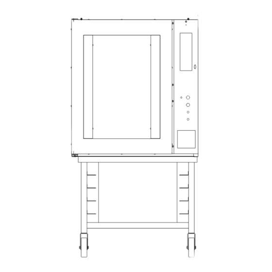
690-NC2 DESCRIPTION/SPECIFICATIONS Description The Oven is a stainless steel, electric, forced air, (convection), oven with steam injection capabilities. This oven offers consistent baking at all rack levels due to the careful positioning of the heating and air circulation systems. In addition to the above, this oven also offers many other features. It is well insulated with a high quality asbestos free insulation. - Page 6 690-NC2 Space Requirements: Figure 3.0 single: 42” Deep x 33” Wide x 35-3/4” high. single with short stand and casters: 62” high. single with tall stand and casters: 75-1/2” stacked ovens with casters: 78” Clearance: Left side = 2”. Right side = 12” without casters to have access to electrical components, 2”...
-
Page 7: Installation / Setup
690-NC2 INSTALLATION / SETUP CAUTION TO QUALIFY FOR WARRANTY COVERAGE, INSTALLATION MUST BE COMPLETED BY AN OLIVER PACKAGING & EQUIPMENT AUTHORIZED SERVICE DEALER. Inspection Before excepting delivery inspect the carton and machine for damage. Note any damage found on the shipping documents. Remember shipping damage is not covered by your warranty, and is the responsibility of the carrier. -
Page 8: Oven Setup
Oven Setup Ovens may be mounted to a fixed surface, attached to an “Oliver” oven rack with casters or stacked. For associated mounting heights for the above options see figure 3.0 on page 2-2. - Page 9 690-NC2 CAUTION SPECIAL HEAVY DUTY ELECTRICAL SERVICES AND WALL DISCONNECTS MUST BE PROVIDED FOR SAFE OPERATION OF THE OVEN. Electrical Connection (continued) The following service requirements are recommended, dependent on the voltage of the unit you have purchased. Your oven’s requirements can be found on the nameplate attached to its rear surface.
-
Page 10: Water Connection
690-NC2 Water Connection All water connections must comply with the basic plumbing code of the Building Officials and Code Service Sanitation Manual of the Food and Drug Administration (FDA) CAUTION WATER PRESSURES GREATER THEN RECOMMENDED CAN CAUSE EXCESS WATER TO ENTER THE OVEN CAUSING WATER TO LEAK AT THE DOOR AND ALSO CAUSE THE TEMPERATURE TO DROP SEVERELY AFFECTING THE BAKE. -
Page 11: Test Cycle
690-NC2 WARNING HOT STEAM CAN CAUSE SEVERE BURNS AND DAMAGE TO THE SENSITIVE ELECTRONICS. VENT STEAM TO OUTSIDE TO AVOID INJURIES AND DAMAGE. Test Cycle (done manually without computer) After completing the Set Up, Electrical and Water connections, and Venting, you may wish to run the oven through a test cycle to verify that everything is ready. -
Page 12: Operating Instructions
690-NC2 OPERATING INSTRUCTIONS Beginning Operation First turn the oven on by pressing the black ‘Start/ Reset’ button below the keyboard and display. The computer will then check the oven and itself for any faults. Then the display will show the current mode which is idle the preset initial temperature is 250 °F. -
Page 13: Idle Mode
690-NC2 Idle Mode From Idle mode you can: • Run an automatic program. • Run a manual program. • Adjust the temperature. • add steam. • open and close the vent. • change the fan setting. Running an Automatic Program 1. -
Page 14: Running Two Automatic Programs At The Same Time
690-NC2 Running two Automatic Programs at the Same Time If two programs are compatible they may be run at the same time. They must both be single stage menus with identical temperatures. While the program is running (Product 1 LED will be lit) enter the second program number (01-40) and hit start. Now both product LED’s will be lit, the one with the shortest time will have a flashing LED and the time remaining will be displayed. -
Page 15: Adjusting The Temperature
690-NC2 START CANCEL START CANCEL Countdown begins. Adjusting the Temperature The temperature can be changed while in manual or idle mode. Here is an example of how to change the temperature from 350 to 380. Display Shows Press Button(s)... Actual temp, Press the temp key again 0690S20043... -
Page 16: Adding Steam
690-NC2 Set temp. to scroll to 380. Press to go back to ‘Time or Idle’. Adding Steam It is possible to inject steam at any time the door is closed by pressing and holding the 7/steam button Opening and Closing the Vent It is possible to toggle the vent open and closed by pressing the 8/vent key . - Page 17 690-NC2 In manual mode the fans can be set to high or low by pressing the 9/fan key In Idle mode the fans can be set to high , low , or cool down using the 9/fan key Cool down allows the oven chamber to quickly cool down by keeping the blowers running while the door is open.
-
Page 18: Programming
690-NC2 PROGRAMMING The following are instructions for editing and creating a menu program. 1. Enter the Program Mode by pressing the up and down keys simultaneously for 5 seconds. 2. Display shows for MENU. 3. Key in the menu number you want to program (01-40), or use the up and down keys to scroll. - Page 19 690-NC2 for stage 2 time. Stage 2 only works for menus 01-20 11. Display will show (For menus 21-40 skip to the Pre-alarm). Use up and down keys or keypad to enter the time in whole minutes. Entering 0 will eliminate stage 2 and skip you past the rest of the stage 2 parameters.
-
Page 20: Troubleshooting
690-NC2 TROUBLESHOOTING WARNING TROUBLE SHOOTING OF ELECTRICAL EQUIPMENT SHOULD BE PERFORMED BY QUALIFIED PERSONNEL ONLY. ELECTRICAL POTENTIAL IS GREAT ENOUGH TO CAUSE INJURY OR DEATH. Error Code Display The error code is visible in the display. The list below outlines the standard error codes associated with this unit. -
Page 21: Solving Other Problems
690-NC2 Error Code Display (continued): Problem Probable Cause Solution Er13- O pen sensor Check for an open probe. Zone 2/Bottom probe open sensor Er14- Probe is out of range. Check probe for short. Zone 2/Bottom probe Should be greater than shorted sensor 90 ohm s. - Page 22 690-NC2 • Check heater bank continuity. • The fault/high limit lamp is on, see the trouble shooting suggestions for this area below. The Fault/High Limit Lamp Is On • Motor has overheated. (The blower motors are equipped with an internal thermal switch).
- Page 23 690-NC2 Steam Is Leaking From the Door It is normal for some steam to escape from the door during the steaming operation, however, if excessive amounts escape you should check the following. • The door seal may be damaged. • The door may not be latching properly.
-
Page 24: Advanced Functions
690-NC2 The Oven Is Overheating This may be a normal condition experienced when the oven is empty. Normally the oven’s program will attempt to correct temperature based on a full oven’s reqirements. • A heat contactor may have failed. • There is an error in your program, if it is a new program check that the temperature was entered correctly. -
Page 25: Advanced Setup Mode (Re-Calibration)
690-NC2 Continued Advanced Functions (Continued) Zone 2 temperature shows the temperature reading of the top probe without offset. Advanced Setup Mode (Re-calibration) To change offset temperature or run on only 1 probe enter the following key sequence. Advance through all parameters by using the key. -
Page 26: Maintenance
690-NC2 MAINTENANCE WARNING NEVER ATTEMPT TO CLEAN OR SERVICE THIS OVEN UNTIL IT HAS BEEN DISCONNECTED FROM THE POWER SUPPLY AND IS COOL TO THE TOUCH. NOTE REMEMBER A CLEAN OVEN WILL LAST LONGER AND WORK BETTER. Cleaning The outside of the oven should be cleaned daily by wiping it with a clean damp cloth or by using any suitable stainless steel cleaner. -
Page 27: Removal And Replacement Guide
690-NC2 Removal and Replacement Guide Removing the Inner Liner: • First remove the nozzle assembly in the back of the oven. • Remove the eight slotted head screws which secure the liner. Six of these screws are in the front of the oven while two additional screws are on the rear panel adjacent to the nozzle assembly. - Page 28 690-NC2 Changing a Bank of Heating Elements (Continued). • Remove the four hex head screws which secure the bank to the housing and remove the bank of elements. • The interior surface where the bank of elements were previously attached should be cleaned completely of any remaining sealant.
- Page 29 690-NC2 Replacing the Interior Door Gasket (Continued) • Replace gasket and use a NSF/FDA approve sealant between the metal and gasket. and gasket end to end. • Set down door frame, rounded gasket side up and run a bead of NSF/FDA approved sealant around top edge of entire gasket.
-
Page 30: Recommended Spare Parts
Switch-Magnetic Proximity Door 5757-4125 Breaker-Circuit 2.5A 5737-2010 Lamp-Fluorescent 5911-9030 Latch-Body 0690-0149 Strike-Door 6542-0003 Glass-Door 6904-6062 Gasket-Door Interior and Exterior 17 ft 5757-8083 Switch-Limit 6310-0003 Motor-Gear 1/110 h.p. (For Vent) For Service Parts Call Oliver Products @ 800-253-3893 (continued) Rev. 2-27-02 0690S20047... - Page 31 Coupling-RTD Sensor 5704-5011 Cable-Computer/Interface 9 Pin Mate-n-Lock 5704-5012 Cable-Computer/Interface12 Pin Mate-n-Lock 5712-3261 Interface-Watlow Compatible 5712-3267 Computer-Oliver/Watlow 5730-2655 Heater-10KW 5757-9710 Switch-Thermal Surface Mount (Hi Limit) 6310-5027 Fan-Axial 3000 RPM (Cooling Fan) For Service Parts Call Oliver Products @ 800-253-3893 Rev. 10-22-2003 0690S20047...
-
Page 32: Electrical Sub Panel
690-NC2 ELECTRICAL SUB PANEL Rev 2-27-09 0690S20050... -
Page 33: Parts List
TRANSFORMER-MULTI-TAPS (all models) 5760-3196 TRANSFORMER-208/380V OVENS ONLY 5760-3195 TRANSFORMER-240/480V OVENS ONLY 5760-3194 RELAY-POWER 3 POLE 25A 5749-8021 SPACER-NYLON 1/2” 5767-5705 SUBPANEL-ELECTRICAL 0690-0039-6 BLOCK-TERMINAL 0-14 GA 5770-7463 BALLAST-DOOR LAMP 5702-2000 FOR SERVICE PARTS CALL OLIVER PRODUCTS @ 800-253-3893 Rev 2-27-09 0690S20050... - Page 34 690-NC2 FRONT PANEL Revised 12/10/2012 0690S20051 10-1...
-
Page 35: Parts List
PANEL-REAR FAN (208/240V) 0690-0038-102 COVER-TOP 0690-0001-002 COVER-HINGE SIDE 0690-0002 COVER-ASS’Y-RECESS POCKET 0690-0074K COVER-ELECTRICAL SIDE REAR 0690-0003-201 PANEL-REAR RIGHT 0690-0018-2 PANEL-REAR CENTER 0690-0018-3 COVER-ELECTRICAL SIDE FRONT 0690-0003-202 DOOR-FUSE 0690-0141 FOR SERVICE PARTS CALL OLIVER PRODUCTS @ 800-253-3893 Revised 12/10/2012 0690S20051 10-2... -
Page 36: Door Assembly
690-NC2 DOOR ASSEMBLY Rev. 12/10/2012 0690S20052 11-1... - Page 37 LATCH-BODY 5911-9030 DOOR-OUTSIDE 0690-0087-2 DOOR-OUTER BACK 0690-0088-3 DOOR-INSIDE ASSEMBLY 0690-0089-2 NUTBAR 0690-0110-2 LAMP-FLUORESCENT 36 WATT 5737-2010 SOCKET-LAMP 5737-2910 HOUSING-LAMP 0690-0022-1 RETAINER-LAMP CLIP 0690-0129 CLIP-HORIZONTAL LAMP 5737-2911 STRIKE-LATCH 0690-0149 FOR SERVICE PARTS CALL OLIVER PRODUCTS @ 800-253-3893 Rev. 12/10/2012 0690S20052 11-2...
-
Page 38: Housing/Chamber Assembly
690-NC2 HOUSING/CHAMBER ASSEMBLY 0690S20053 12-1... -
Page 39: Parts List
0690-0063 PLATE-LOWER SPLICE 0690-0064 PLATE-SIDE SPLICE 0690-0065 PLATE-MOTOR BAFFLE 0690-0067-2 MOTOR-BLOWER 230/460/3 0690-0004 *015 HOUSING-PACKING ADJUSTABLE 0690-0158 INNER CHAMBER-8 SHELF 0690-0020 BAFFLE-UPPER 0690-0056 BAFFLE-LOWER 0690-0057 *ITEMS NOT SHOWN FOR SERVICE PARTS CALL OLIVER PRODUCTS @ 800-253-3893 Rev. 3/8/05 0690S20053 12-2... -
Page 40: Water System Assembly
690-NC2 WATER SYSTEM ASSEMBLY 0690S20054 13-1... -
Page 41: Parts List
WATER SYSTEM ASSEMBLY PARTS LIST ITEM NO PART DESCRIPTION PART NUMBER MANIFOLD-ASSEMBLED 0690-0011 VALVE-SOLENOID 2WAY 5148-6718 VALVE-WATER FLOW CONTROL 5148-7408 NIPPLE-1/4 NPT X 1-1/2 5115-8250 BUSHING-REDUCER 3/8x1/4 NPT 5115-8300 NIPPLE-CLOSE 3/8” X 1” 5115-8251 FOR SERVICE PARTS CALL OLIVER PRODUCTS @ 800-253-3893 0690S20054 13-2... -
Page 42: Damper Control Assembly
690-NC2 DAMPER CONTROL ASSEMBLY 0690S20055 14-1... -
Page 43: Parts List
5604-6951 SWITCH-LIMIT (DAMPER) 5757-8083 BLOCK-TERMINAL 5770-7169 COLLAR-SET 5806-7053 MOTOR-GEAR 6310-0003 PLATE-DAMPER 0690-0055-1 BRACKET-FLAP (2 X 1/2) 0690-0101 FLAP-RUBBER PRES. RELIEF 0690-0102 SCREW-MACH #10 X 3/4 5843-5240 NUT-HEX MACHINE #10-24 5832-0578 FOR SERVICE PARTS CALL OLIVER PRODUCTS @ 800-253-3893 0690S20055 14-2... - Page 44 690-NC2 208/240V WIRING DIAGRAM #0690D12025 Revised 2-27-09 0690S20056 15-1...
- Page 45 690-NC2 375/480V WIRING DIAGRAM #0690D12026 Revised 2-27-09 0690S20056 15-2...
- Page 46 690-NC2 INTERFACE BOARD SCHEMATICS 0690S20056 15-3...
- Page 47 WARRANTY PARTS Oliver Packaging & Equipment Company warrants that if any part of the equipment (other than a part not manufactured by Oliver Packaging & Equipment ) proves to be defective (as defined below) within one year after shipment, and if Buyer returns the defective part to Oliver Packaging & Equipment within one year, Freight Prepaid to Oliver Packaging &...
- Page 48 4. The service dealer will then complete an invoice and send it to the Parts and Service Department at Oliver Packaging & Equipment Company. 5. The Parts and Service Manager of Oliver Packaging and Equipment Company will review the invoice and returned parts, if applicable, and approve for payment.
- Page 49 This policy applies to all parts returned to the factory whether for warranted credit, replacement, repair or re-stocking. Oliver Packaging and Equipment Company requires that the customer obtain a Return Material Authorization (RMA) number before returning any part. This number should appear on the shipping label and inside the shipping carton as well.
Need help?
Do you have a question about the NC and is the answer not in the manual?
Questions and answers